Downloaded 124 times
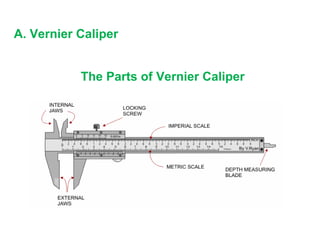

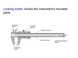
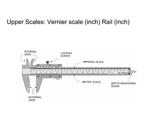


The document describes two high accuracy measuring devices: the vernier caliper and micrometer. The vernier caliper contains scales to measure internal and external lengths in both inches and millimeters, as well as a depth probe. To take a measurement, you read the centimeter mark on the fixed scale and the millimeter mark that lines up on the vernier scale, then add any millimeters indicated on the vernier scale. The micrometer uses a rotating thimble to precisely measure thickness between fixed rods, reading the millimeter mark on the barrel and hundredths mark on the thimble, then adding them together. Both devices provide precise linear measurements down to hundredths of a millimeter.


