1) The document describes how to use a micrometer screw gauge to measure the diameter of a wire and thickness of a glass plate.
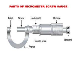
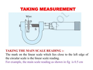
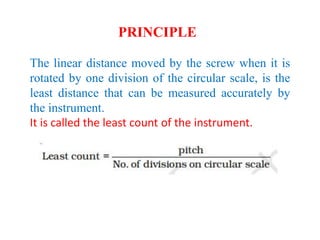
2) A micrometer screw gauge has a frame that holds an anvil and barrel. Turning the thimble moves a screw to take precise measurements.
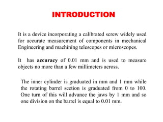
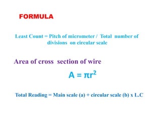
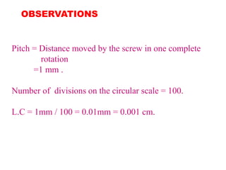
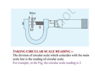
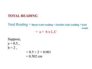
3) To measure the diameter of a wire, it is inserted between the screw and anvil. Readings from the main and circular scales are used to calculate the diameter to within 0.01 mm.


![谷歌留痕技术 [ 𝙩𝙤𝙥 𝟮𝟯𝟯. 𝙘 𝙤𝙢 ]](https://cdn.slidesharecdn.com/ss_thumbnails/top233-260130174328-3833018c-thumbnail.jpg?width=640&height=640&fit=bounds)


