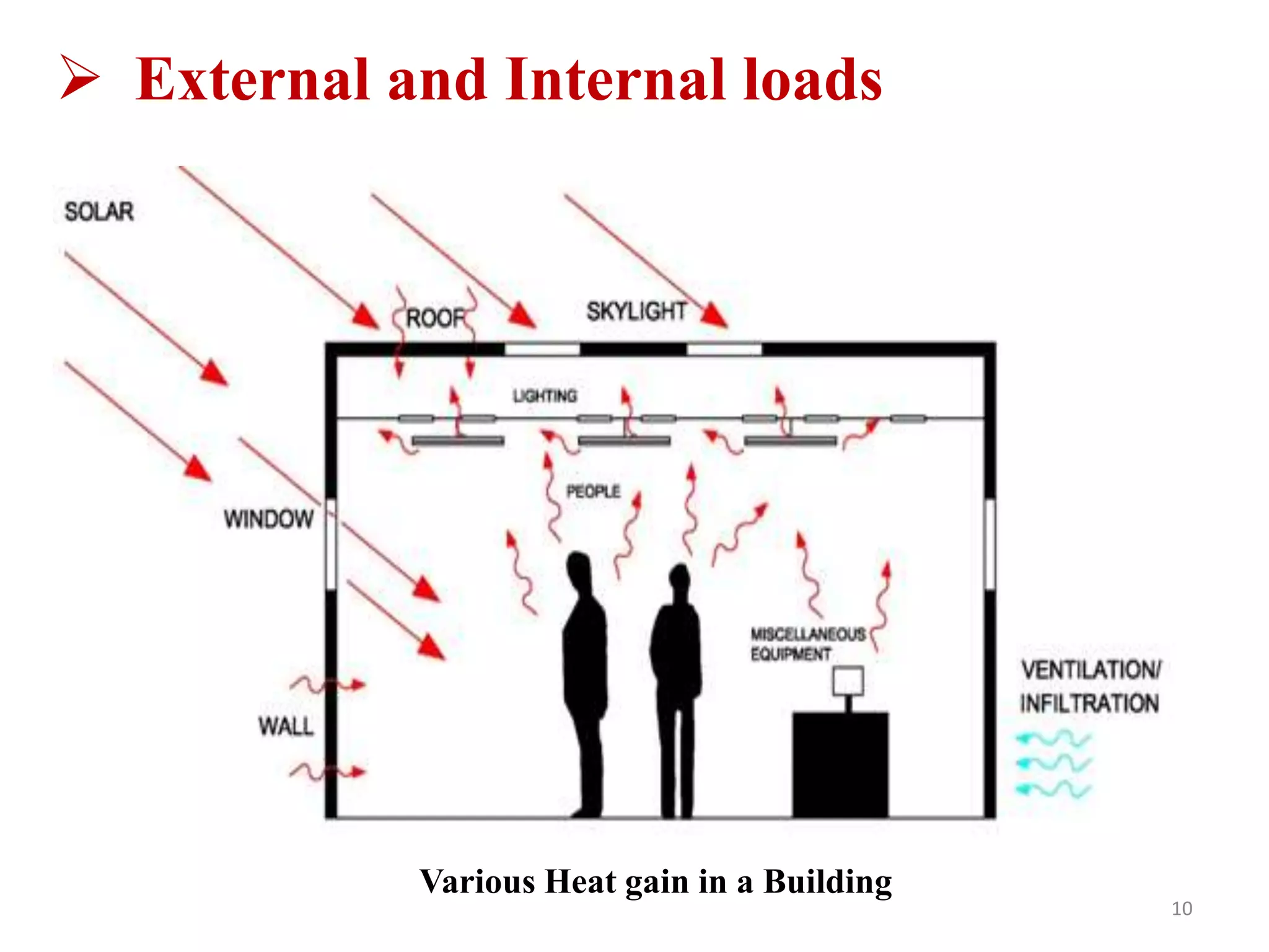
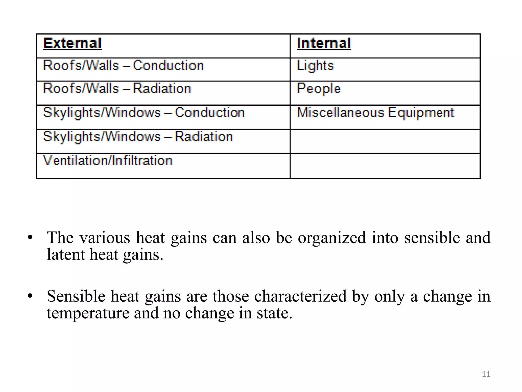
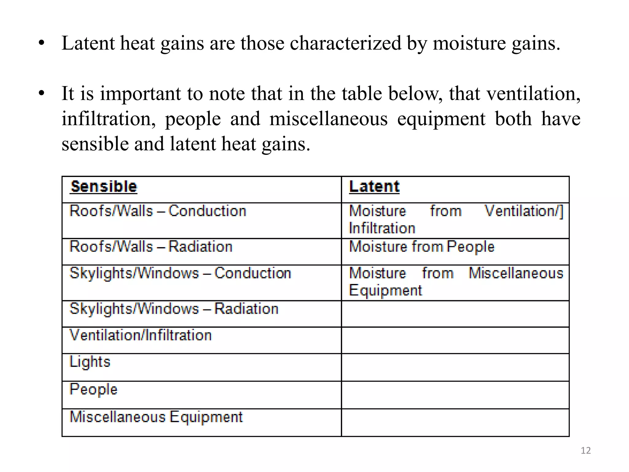
This document discusses heating and cooling load calculations for buildings. It covers calculating heating loads by estimating transmission heat losses through walls, infiltration, and ductwork. Cooling load calculations are more complex as they consider time-varying outdoor conditions and internal heat gains. Methods for calculating cooling loads include using the Cooling Load Temperature Difference (CLTD) method for walls and roofs and considering solar heat gain factors for windows. The assumptions behind design cooling loads and calculating people loads are also outlined.
To design any air-conditioning unit, estimation of heating or cooling load is very important. It helps us in design different devices most importantly the humidifier (in case of winter) or de-humidifier (in case of summer).
Fundamentals of HVAC Systems is a thorough introduction on how HVAC systems control temperature, air quality and air circulation in a conditioned space.
Ideal for recent engineering graduates working in the HVAC&R industry, experienced engineers entering HVAC&R from another engineering area, as well as architects, technicians, construction or building management professionals who need to increase their knowledge of HVAC systems.
This course reader can function as a stand-alone reference, or may accompany the eLearning course, Fundamentals of HVAC Systems, online modules.
What is meant by “Airconditioning”?
Human Comfort
Why do we need A.C.?
Advantages and Disadvantage of A.C.
Ideal room temperature
some terminology-
Dry-bulb temperature
Wet-bulb temperature:
Dew point
Latent heat
Absolute humidity
Relative humidity
Specific humidity
Sensible heat
Evaporating Cooling
Condensation
Enthalpy
Entropy
7. Classification of air conditioners
8. Windows AC- advantages
Parts of the Window Air Conditioners
Working
The refrigeration system,
Air circulation system-room air cycle and
The hot air cycle.
Ventilation system,
Control system,
electrical protection system.
9.Split or Ductless AC-
Advantages, parts indoor and outdoor,
Types-
Wall mounted
Floor mounted/Tower AC
Ceiling mounted/Cassette AC
Multi Split ACs
10. Central Air Conditioning System
Advantages and disadvantages
11. Key differences between "Window", "Split" and a "cassette" air conditioners.
12. Cooling capacity
13. Energy Efficiency
14.Energy Consumption
15.Energy Efficiency Ratio
16.Energy Saving Methods
17.Some AC brands
CADmantra Technologies Pvt. Ltd. is one of the best Cad training company in northern zone in India . which are provided many types of courses in cad field i.e AUTOCAD,SOLIDWORK,CATIA,CRE-O,Uniraphics-NX, CNC, REVIT, STAAD.Pro. And many courses
Contact: www.cadmantra.com
www.cadmantra.blogspot.com
www.cadmantra.wix.com
Cold Storage Room Design. How you can do that? How you can learn that? Product heat load, infiltration heat load, internal heat load, refrigeration equipment heat load, transportation of refrigerated foods, safety factor, thermal conductivity,
it is basic introduction about Calculation of cooling load TETD due to sunlight & shaded roofs &walls using table,Load due to air filtration and Load due to ventilation.
The building envelope is physical separator between the exterior and the interior of the building and fenestration systems.
Envelope design strongly affects the visual and thermal comfort of the occupants, as well as energy consumption in the building.
Natural ventilation and air movement could-be considered under the heading of 'structural controls’ as it does not rely on any form of energy supply or mechanical installation, but due to its importance for human comfort, it deserves a separate section.
This Presentation talks about low cooling strategies for buildings viz. radiant heating/cooling, geothermal heat exchange, rock beds and ground tunnel with examples and climate consideration.
The International Journal of Engineering & Science is aimed at providing a platform for researchers, engineers, scientists, or educators to publish their original research results, to exchange new ideas, to disseminate information in innovative designs, engineering experiences and technological skills. It is also the Journal's objective to promote engineering and technology education. All papers submitted to the Journal will be blind peer-reviewed. Only original articles will be published.
The papers for publication in The International Journal of Engineering& Science are selected through rigorous peer reviews to ensure originality, timeliness, relevance, and readability.
NUMERICAL SIMULATIONS OF HEAT AND MASS TRANSFER IN CONDENSING HEAT EXCHANGERS...ssuser7dcef0
Power plants release a large amount of water vapor into the
atmosphere through the stack. The flue gas can be a potential
source for obtaining much needed cooling water for a power
plant. If a power plant could recover and reuse a portion of this
moisture, it could reduce its total cooling water intake
requirement. One of the most practical way to recover water
from flue gas is to use a condensing heat exchanger. The power
plant could also recover latent heat due to condensation as well
as sensible heat due to lowering the flue gas exit temperature.
Additionally, harmful acids released from the stack can be
reduced in a condensing heat exchanger by acid condensation. reduced in a condensing heat exchanger by acid condensation.
Condensation of vapors in flue gas is a complicated
phenomenon since heat and mass transfer of water vapor and
various acids simultaneously occur in the presence of noncondensable
gases such as nitrogen and oxygen. Design of a
condenser depends on the knowledge and understanding of the
heat and mass transfer processes. A computer program for
numerical simulations of water (H2O) and sulfuric acid (H2SO4)
condensation in a flue gas condensing heat exchanger was
developed using MATLAB. Governing equations based on
mass and energy balances for the system were derived to
predict variables such as flue gas exit temperature, cooling
water outlet temperature, mole fraction and condensation rates
of water and sulfuric acid vapors. The equations were solved
using an iterative solution technique with calculations of heat
and mass transfer coefficients and physical properties.
An Approach to Detecting Writing Styles Based on Clustering Techniquesambekarshweta25
An Approach to Detecting Writing Styles Based on Clustering Techniques
Authors:
-Devkinandan Jagtap
-Shweta Ambekar
-Harshit Singh
-Nakul Sharma (Assistant Professor)
Institution:
VIIT Pune, India
Abstract:
This paper proposes a system to differentiate between human-generated and AI-generated texts using stylometric analysis. The system analyzes text files and classifies writing styles by employing various clustering algorithms, such as k-means, k-means++, hierarchical, and DBSCAN. The effectiveness of these algorithms is measured using silhouette scores. The system successfully identifies distinct writing styles within documents, demonstrating its potential for plagiarism detection.
Introduction:
Stylometry, the study of linguistic and structural features in texts, is used for tasks like plagiarism detection, genre separation, and author verification. This paper leverages stylometric analysis to identify different writing styles and improve plagiarism detection methods.
Methodology:
The system includes data collection, preprocessing, feature extraction, dimensional reduction, machine learning models for clustering, and performance comparison using silhouette scores. Feature extraction focuses on lexical features, vocabulary richness, and readability scores. The study uses a small dataset of texts from various authors and employs algorithms like k-means, k-means++, hierarchical clustering, and DBSCAN for clustering.
Results:
Experiments show that the system effectively identifies writing styles, with silhouette scores indicating reasonable to strong clustering when k=2. As the number of clusters increases, the silhouette scores decrease, indicating a drop in accuracy. K-means and k-means++ perform similarly, while hierarchical clustering is less optimized.
Conclusion and Future Work:
The system works well for distinguishing writing styles with two clusters but becomes less accurate as the number of clusters increases. Future research could focus on adding more parameters and optimizing the methodology to improve accuracy with higher cluster values. This system can enhance existing plagiarism detection tools, especially in academic settings.
Water billing management system project report.pdfKamal Acharya
Our project entitled “Water Billing Management System” aims is to generate Water bill with all the charges and penalty. Manual system that is employed is extremely laborious and quite inadequate. It only makes the process more difficult and hard.
The aim of our project is to develop a system that is meant to partially computerize the work performed in the Water Board like generating monthly Water bill, record of consuming unit of water, store record of the customer and previous unpaid record.
We used HTML/PHP as front end and MYSQL as back end for developing our project. HTML is primarily a visual design environment. We can create a android application by designing the form and that make up the user interface. Adding android application code to the form and the objects such as buttons and text boxes on them and adding any required support code in additional modular.
MySQL is free open source database that facilitates the effective management of the databases by connecting them to the software. It is a stable ,reliable and the powerful solution with the advanced features and advantages which are as follows: Data Security.MySQL is free open source database that facilitates the effective management of the databases by connecting them to the software.
Saudi Arabia stands as a titan in the global energy landscape, renowned for its abundant oil and gas resources. It's the largest exporter of petroleum and holds some of the world's most significant reserves. Let's delve into the top 10 oil and gas projects shaping Saudi Arabia's energy future in 2024.
Online aptitude test management system project report.pdfKamal Acharya
The purpose of on-line aptitude test system is to take online test in an efficient manner and no time wasting for checking the paper. The main objective of on-line aptitude test system is to efficiently evaluate the candidate thoroughly through a fully automated system that not only saves lot of time but also gives fast results. For students they give papers according to their convenience and time and there is no need of using extra thing like paper, pen etc. This can be used in educational institutions as well as in corporate world. Can be used anywhere any time as it is a web based application (user Location doesn’t matter). No restriction that examiner has to be present when the candidate takes the test.
Every time when lecturers/professors need to conduct examinations they have to sit down think about the questions and then create a whole new set of questions for each and every exam. In some cases the professor may want to give an open book online exam that is the student can take the exam any time anywhere, but the student might have to answer the questions in a limited time period. The professor may want to change the sequence of questions for every student. The problem that a student has is whenever a date for the exam is declared the student has to take it and there is no way he can take it at some other time. This project will create an interface for the examiner to create and store questions in a repository. It will also create an interface for the student to take examinations at his convenience and the questions and/or exams may be timed. Thereby creating an application which can be used by examiners and examinee’s simultaneously.
Examination System is very useful for Teachers/Professors. As in the teaching profession, you are responsible for writing question papers. In the conventional method, you write the question paper on paper, keep question papers separate from answers and all this information you have to keep in a locker to avoid unauthorized access. Using the Examination System you can create a question paper and everything will be written to a single exam file in encrypted format. You can set the General and Administrator password to avoid unauthorized access to your question paper. Every time you start the examination, the program shuffles all the questions and selects them randomly from the database, which reduces the chances of memorizing the questions.
Student information management system project report ii.pdfKamal Acharya
Our project explains about the student management. This project mainly explains the various actions related to student details. This project shows some ease in adding, editing and deleting the student details. It also provides a less time consuming process for viewing, adding, editing and deleting the marks of the students.
Using recycled concrete aggregates (RCA) for pavements is crucial to achieving sustainability. Implementing RCA for new pavement can minimize carbon footprint, conserve natural resources, reduce harmful emissions, and lower life cycle costs. Compared to natural aggregate (NA), RCA pavement has fewer comprehensive studies and sustainability assessments.
2. Objectives
1. Introduction to Thermal Comfort
2. Introduction to Heating and cooling load
calculations
3. Heating load calculations
4. Cooling load calculations using CLTD/CLF
method
5. Estimation of the cooling capacity of the system
2
3. Thermal comfort -Definition
• “A condition of mind that expresses satisfaction with
the thermal environment”
-ASHRAE
• The absence of discomfort: a person feels neither too
warm nor too cold”
- Mclntyre 1980
4. Thermal Comfort
• The human body has ways to adjust (increase or decrease)
its heat loss, for example by bringing more or less blood to
vessels right under the skin or by changing the total amount
of blood in the body, with more blood produced under
warmer conditions to expel heat more effectively.
• Sweating and the resulting evaporation is another
physiological mechanism to expel heat, but it is not one that
we would call comfortable.
• Thus, we can feel thermally comfortable within a range of
temperatures, but that this range is limited. Experience
reveals that the comfort range for most people extends from
68oF (20oC) to 78oF (25oC).
5. Parameter affecting Thermal comfort
• Air temperature
• Exchange of radiation
• Air movement
• Humidity
• Activity
• Clothing
6. Introduction:
• Heating and cooling load calculations are carried out to
estimate the required capacity of heating and cooling
systems, which can maintain the required conditions in the
conditioned space.
• To estimate the required cooling or heating capacities, one
has to have information regarding the design indoor and
outdoor conditions, specifications of the building,
specifications of the conditioned space (such as the
occupancy, activity level, various appliances and equipment
used etc.) and any special requirements of the particular
application.
• For comfort applications, the required indoor conditions are
fixed by the criterion of thermal comfort.
6
7. Heating versus cooling load calculations:
• As the name implies, heating load calculations are carried out to
estimate the heat loss from the building in winter so as to arrive
at required heating capacities.
• Normally during winter months the peak heating load occurs
before sunrise and the outdoor conditions do not vary
significantly throughout the winter season.
• In addition, internal heat sources such as occupants or
appliances are beneficial as they compensate some of the heat
losses.
• As a result, normally, the heat load calculations are carried out
assuming steady state conditions (no solar radiation and steady
outdoor conditions) and neglecting internal heat sources.
7
8. • This is a simple but conservative approach that leads to
slight overestimation of the heating capacity. For more
accurate estimation of heating loads, one has to take into
the thermal capacity of the walls and internal heat sources,
which makes the problem more complicated.
• For estimating cooling loads, one has to consider the
unsteady state processes, as the peak cooling load occurs
during the day time and the outside conditions also vary
significantly throughout the day due to solar radiation.
• In addition, all internal sources add on to the cooling loads
and neglecting them would lead to underestimation of the
required cooling capacity and the possibility of not being
able to maintain the required indoor conditions.
8
9. Heating load calculations:
• There are two kinds of heat losses:
a) The heat transmitted through the walls, ceiling, floor,
glass, or other surfaces;
b) The heat required to warm outdoor air entering the space.
• One has to estimate only the sensible and latent heat losses
from the building walls, roof, ground, windows, doors, due to
infiltration and ventilation.
• The actual heat loss problem is transient because the outdoor
temperature, wind velocity, and sunlight are constantly
changing.
• However, the difference may not be very high as long as the
internal heat generation is not very large (i.e., when the
building is not internally loaded).
9
10. External and Internal loads
10
Various Heat gain in a Building
11. 11
• The various heat gains can also be organized into sensible and
latent heat gains.
• Sensible heat gains are those characterized by only a change in
temperature and no change in state.
12. 12
• Latent heat gains are those characterized by moisture gains.
• It is important to note that in the table below, that ventilation,
infiltration, people and miscellaneous equipment both have
sensible and latent heat gains.
13. Thermal mass and Time lag factor
• When completing load calculations it is important to
understand the time lag factor. When the sun shines
upon a wall face early in the morning, although the
wall does experience a heat load, the amount of heat
load experienced IN the building at that time is
minimal. This is due to the thermal mass of the wall.
• Thermal mass is also known as heat capacity and is
defined as the ability of a material to absorb heat.
• The use of thermal mass is shown in buildings that
have high thermal mass walls that absorb heat during
the day, store the heat during occupied periods and
release the heat during the night when it is cool.
13
14. • The heat transferred through walls, ceilings, roof,
window glass, floors, and doors is all sensible heat
transfer, referred to as transmission heat loss and
computed from
Q = UA(ti -to )
o Where the area A is the net area for the given
component for which U was calculated.
• A separate calculation is made for each different
surface in each room of the structure.
14
Transmission heat losses
15. Infiltration
• Most structures have some air leakage or infiltration. This
results in a heat loss, because the cold dry outdoor air
must be heated to the inside design temperature and
moisture must be added to increase the humidity to the
design value.
• The sensible heat required (to increase the temperature) is
given by
𝑞s = 𝑚ocp (ti - to )
where:
𝑚o = mass flow rate of the infiltrating air, lbm/hr or kg/s
cp = specfic heat of the air, Btu/(lbm-F) or J/(kg-C)
15
16. • Infiltration is usually estimated on the basis of volume
flow rate at outdoor conditions.so the previous equation
becomes:
𝒒 =
𝑸𝒄𝒑(𝒕𝒊 − 𝒕𝒐)
𝒗𝒐
o where:
Q = volume flow rate, ft3/hr or m3/s
vo = specfic volume, ft3/lbm or m3/kg
• The latent heat required to humidify the air is given by
ql= mo(Wl - Wo)ifg
o where:
Wi − Wo = difference in design humidity ratio, lbmv/lbma or kgv/kga
ifg = latent heat of vaporization at indoor conditions, Btu/lbmv or J/kgv
16
17. • In terms of volume flow rate of air, above equation
becomes
𝒒𝒍 =
𝑸 𝑾𝒊 − 𝑾𝒐 𝒊𝒇𝒈
𝑽𝒐
• Another approach for estimating the air infiltration in
building structures are
a) Air-Change Method
b) Crack Method
17
18. Air-Change Method
• It is based on an assumed number of air changes per hour
based on experience.
• Experienced engineers will often simply make an assumption
of the number of air changes per hour (ACH) that a building
will experience, based on their appraisal of the building type,
construction, and use.
• The range will usually be from 0.5 ACH (very low) to 2.0
ACH (very high).
• Modern office buildings may experience infiltration rates as
low as 0.1 ACH.
• This approach is usually satisfactory for design load
calculation but not recommended for the beginner.
18
19. • The infiltration rate is related to ACH and space volume
as follows:
Q = ACH (V)/CT
o Where
Q = infiltration rate, cfm or m3/s
ACH = number of air changes per hour, hr−1
V = gross space volume, ft3 or m3
CT = constant, 60 for English units and 3600 for SI
19
20. Crack Method
• Outdoor air infiltrates the indoor space through cracks
around doors, windows, lighting fixtures, and joints
between walls and floor, and even through the building
material itself.
• The amount depends on the total area of the cracks, the
type of crack, and the pressure difference across the crack.
• The volume flow rate of infiltration may be calculated by
𝐐 = ACΔPn
o where:
A = effective leakage area of the cracks
C = flow coefficient, which depends on the type of crack and the nature of
the flow in the crack
ΔP = outside − inside pressure difference, Po − Pi
n = exponent that depends on the nature of the flow in the crack,
< 0.4 < n < 1.0.
20
21. Variation of Wall averaged pressure
coefficients
21
Variation of wall averaged pressure coefficients for a low-rise building
(Source: ASHRAE Cooling and Heating Load Calculation Manual, 2nd ed., 1992.)
22. 22
Variation of wall averaged pressure coefficients for a tall building
(Source: ASHRAE Cooling and Heating Load Calculation Manual, 2nd ed., 1992.)
23. 23
Average roof pressure coefficients for a tall building.
(Source: ASHRAE Cooling and Heating Load Calculation Manual, 2nd ed., 1992.)
24. Heat losses from air ducts
• The heat losses of a duct system can be considerable
when the ducts are not in the conditioned space. Proper
insulation will reduce these losses but cannot
completely eliminate them.
• The loss may be estimated using the following relation:
𝒒 = UAs Δtm
o where:
U = overall heat transfer coefficient, Btu/(hr-ft2-F) or W/(m2-C)
As = outside surface area of the duct, ft2 or m2
Δtm= mean temperature difference between the duct air and the
environment, F or °C
24
25. Uncertainty
• Calculating heat gains and determining cooling loads has
very high uncertainty. This is because of the many
assumptions that must be made like occupant loads,
occupant, schedules, outdoor weather conditions,
equipment schedules and heat gains, etc.
25
26. Cooling load-
• The cooling load is the amount of heat energy that would
need to be removed from a space (cooling) to maintain the
temperature in an acceptable range.
• Cooling load is the rate at which sensible and latent
heat must be removed from the space to maintain a
constant space dry-bulb air temperature and humidity.
• Sensible heat into the space causes its air temperature to
rise while latent heat is associated with the rise of the
moisture content in the space.
26
27. Cooling load calculations:
• Load calculations involve a systematic and stepwise
procedure that takes into account all the relevant building
energy flows.
• The cooling load experienced by a building varies in
magnitude from zero (no cooling required) to a maximum
value.
• The design cooling load is a load near the maximum
magnitude, but is not normally the maximum.
• Design cooling load takes into account all the loads
experienced by a building under a specific set of assumed
conditions.
27
29. Methods of estimating cooling loads:
• Cooling load calculations are inherently more
complicated as it involves solving unsteady equations
with unsteady boundary conditions and internal heat
sources.
• Generally, cooling load calculations involve a
systematic, stepwise procedure, using which one can
arrive at the required system capacity by taking into
account all the building energy flows.
29
31. • More accurate load estimation methods involve a
combination of analytical methods and empirical
results obtained from actual data, for example the use
of Cooling Load Temperature Difference (CLTD) for
estimating fabric heat gain and the use of Solar Heat
Gain Factor (SHGF) for estimating heat transfer
through fenestration.
• These methods are very widely used by air
conditioning engineers as they yield reasonably
accurate results and estimations can be carried out
manually in a relatively short time.
• ASHRAE suggests different methods for estimating
cooling and heating loads based on applications, such
as for residences, for commercial buildings etc.
31
32. The assumptions behind design cooling
load are as follows:
1. Design outside conditions are selected from a long-
term statistical database. The conditions will not
necessarily represent any actual year, but are
representative of the location of the building.
2. The load on the building due to solar radiation is
estimated for clear sky conditions.
3. The building occupancy is assumed to be at full
design capacity.
4. All building equipment and appliances are considered
to be operating at a reasonably representative
capacity.
32
33. Cooling Load Calculations - Roof/Wall
• The loads from the roofs and walls are conductive
loads. Heat from the outdoors is conducted through the
roofing or wall materials as it enters the space.
• If the problem assumes no radiation loads or does not
take into account time, then the only load is the
conductive load from the temperature difference
between the outdoors and indoors, which is as shown
below.
33
34. 34
Simplified heat gain through Wall and roof
𝑼 = 𝟏
𝟏
𝑹𝑪𝒐𝒏𝒄 +𝑹𝒊𝒏𝒔 + 𝑹𝒈𝒚𝒑
𝐐
= 𝐔 ∗ 𝐀 ∗ (𝐓𝐨𝐮𝐭𝐝𝐨𝐨𝐫 − 𝐓𝐢𝐧𝐝𝐨𝐨𝐫)
35. • However, the heat effect from the roofs and walls is not
this simple.
• The radiation from the sun onto the building and the time
it takes for the heat to transmit through the materials must
be taken in to account.
• In order to calculate the total effect of the difference
between the indoor and outdoor temperature, the effect of
the solar radiation onto the walls and roofs and the time
factor due to the heat storage of the roof/wall material, the
engineer should use the Cooling Load Temperature
Difference or CLTD.
• These values can be found in the ASHRAE Fundamentals
book 1997 edition and older. These tables are organized
by latitude, roof or wall type, month and wall facing
orientation direction.
35
36. 36
• It is only important to understand what CLTD is and
how to use it when given it in a problem.
• It is also important to note that the CLTD is a simplified
approach to determining the heat load due to roofs and
walls. In actuality the heat load due to the roofs/walls
will also be dependent on many other conditions like the
indoor conditions and the heat radiated from the inner
wall/roof to the indoor space.
𝑸 = 𝑼 ∗ 𝑨 ∗ 𝑪𝑳𝑻𝑫
38. Cooling Load Calculations -
Skylight/Window
• The heat loads form the skylights and windows can be
broken up into (2) types of loads, conductive and
radiation loads.
• The conductive loads for skylights and windows use
the same formula as that of the roofs and windows,
shown below again.
Conductive loads
Q=U*A*CLTD
38
39. • The radiation loads or solar transmission is calculated
by multiplying the area of the window or skylight by
the shading coefficient and the solar cooling load
factor.
Q=U*SC*SCL
o Wℎ𝑒𝑟𝑒
SC = shading coefficient
SCL = solar cooling load factor
• The shading coefficient is the ratio of the specific
window or skylight's solar transmission compared to
1/8" clear glass. The shading coefficient is typically
specific to the glass manufacturer and can be found in
the manufacturer's product data.
39
40. • In lieu of SC, the term Solar Heat Gain Coefficient
(SHGC) is being used by window/skylight
manufacturers. This term is simply found by dividing
the SC by 1.15.
• A lower SHGC or SC means that the glass lets in less
solar gain and a higher SHGC or SC means that the
glass allows more solar gain through.
• The National Fenestration Rating Council (NFRC)
rates glass and certifies the SHGC and U-Factor.
Additional values like Visible Transmittance, Air
Leakage and Condensation Resistance are also tested
and certified.
40
41. Cooling Load Calculations - People
• The heat loads from a person depend on the activity
level of the person. ASHRAE has tabulated heat loads
both sensible and latent heat gains from people based on
their activity levels, refer to ASHRAE Fundamentals.
• The loads from people can be calculated using these
heat gain values, the number of people and the cooling
load factor, as shown in the equations below. The
cooling load factor takes into account the time lag factor
and if it is not given it should be assumed to be 1.0.
Sensible loads
Q = N* SHG*CLF
41
42. o Where
N = number of people, SHG = sensible heat gain, activity dependent
CLF = cooling load factor
• Latent loads
• R-Value stands for thermal resistance and it is
representative of a material’s ability to resist heat.
This is opposite of the U-Factor and thermal
conductance which are measures of a materials
ability to conduct heat. The relationship between
the R-Value, U-Factor and thermal conductance is
shown in the following formula.
Q =N*LHG*CLF
o Where
N = number of people, SHG = latent heat gain, activity dependent
CLF = cooling load factor
42
43. Cooling Load Calculations - Lighting
• The heat load from lighting in a building is found by
summing up the number of lights of each type and
wattage, multiplying this number by the usage factor and
the special allowance factor, as shown in the below
equation.
𝑸 = 𝑵 ∗ 𝑾𝒂𝒕𝒕𝒔 ∗
𝟑. 𝟒𝟏𝟐
𝑩𝒕𝒖
𝒉𝒓
𝒘𝒂𝒕𝒕𝒔
∗ 𝑼𝑭 ∗ 𝑺𝑨𝑭 ∗ 𝑺𝑭
o Where
N = number of light type
UF = usage factor
SAF = special allowance factor
SF = space fraction
43
44. • The wattage of the light is based on the manufacturer
reported value for the lamps in the lighting fixture,
without taking into account the ballast.
• The lighting use factor is the ratio of the time the lights
will be in use. This factor is typically 1.0 for most
applications like offices, classrooms, stores, hospitals,
etc.
• The usage factor may vary for a movie theater or
inactive storage space.
• The special allowance factor takes into account the heat
from ballasts. This factor is typically 1.2 for fluorescent
lights and 1.0 for incandescent lights due to the lack of
ballasts in incandescent lights.
44
46. • Finally, the space fraction is the fraction of the total
heat from the lights that is transmitted to the space.
• Lights located at the ceiling may have a percentage of
its heat transmitted into the plenum and not into the
space. This means that the air conditioning system, if
the return is ducted, will not see the percentage of the
heat that is transmitted to the plenum. If the plenum is
used as a return, then the air conditioning will see the
total heat from the lighting.
• For example, the space fraction for a hung fluorescent
light (non-ceiling) will be 1.0, because the light is
completely into the space. On the other hand a ceiling
recessed light could have a space fraction of 0.5,
meaning that 50% of its heat is transmitted to the
plenum and the other 50% is transmitted to the space. 46
47. Cooling Load Calculations - Miscellaneous
Equipment
• The heat gains from miscellaneous equipment can be
found by the following equations.
𝑸 = 𝟐𝟓𝟒𝟓
𝑩𝒕𝒖
𝒉𝒓
𝑯𝑷
∗
𝑷
ℰ𝒎𝒐𝒕𝒐𝒓
∗ 𝑭𝑼 ∗ 𝑭𝒍
o Where
P = horsepower of motor
ℰ𝒎𝒐𝒕𝒐𝒓 = efficiency of motor
FU= usage factor of the motor
FL = load factor of the motor
47
48. • The first equation is used for motors, where P is equal to
the nominal horsepower of the motor. Dividing the
horsepower of the motor by the efficiency of the motor
allows the heat gains due to the motor and the heat gains
due to the inefficiency of the motor to be taken into
account.
• If the motor is used continuously then the usage factor
will be 1.0. Otherwise the usage factor will be the
fraction of the time that it is used divided by the total
time the space is occupied.
• The load factor of the motor takes into account the fact
that motors rarely run at its nominally rated capacity. For
example, if a 1 HP motor actually operates at 0.75 HP
then the load factor will by 0.75.
48
49. • The second equation describes heat gain from everyday
appliances like microwaves, toasters, ranges, ovens and
computers.
• The input energy is found by researching the
manufacturer's product data or by referring to typical
values reported in ASHRAE Fundamentals. ASHRAE
Fundamentals also has typical usage factors and radiated
heat fractions for typical equipment.
• Also shown in ASHRAE Fundamentals are the sensible
heat gains for typical pieces of equipment, which
bypasses the formula below.
𝑸 = 𝒒𝒊𝒏𝒑𝒖𝒕 ∗ 𝑭𝑼 ∗ 𝑭R
49
50. o Where
qinput= input to the equipment
FU = usage factor
FR = fraction of the total heat heat that to the space
50
51. Cooling Load Calculations - Infiltration
• Infiltration is described as outside air that leaks into a
building structure. These leaks could be through the
building construction or through entry doors.
Infiltration heat gains are found by the following
equations.
𝑸 = 𝟔𝟎
𝒎𝒊𝒏
𝒉𝒐𝒖𝒓
∗ 𝟎. 𝟎𝟕𝟓
𝒍𝒃
𝒇𝒕𝟑 ∗ 𝑪𝑭𝑴 ∗ ∆𝒉(
𝐵𝑡𝑢
𝑙𝑏
)
𝑸𝟒. 𝟓 ∗ 𝑪𝑭𝑴 ∗∗ ∆𝒉(
𝐵𝑡𝑢
𝑙𝑏
)
• The first equation is the total heat gains using
enthalpy. In this equation, the volumetric flow rate of
the infiltration or ventilation air must be known. This
value is converted and multiplied by the difference in
enthalpy between the outdoor air conditions and the
indoor air conditions. 51
52. • The following two equation split the total heat gain into
the sensible and latent heat loads.
• Sensible Heat Gains are calculated by multiplying the
CFM of the infiltrated air by the difference in the
temperatures of the indoor and outdoor air.
𝑸𝒔𝒆𝒏𝒔𝒊𝒃𝒍𝒆 = 𝟔𝟎
𝒎𝒊𝒏
𝒉𝒐𝒖𝒓
∗ 𝟎. 𝟎𝟕𝟓
𝒍𝒃
𝒇𝒕𝟑 ∗ 𝑪𝑭𝑴 ∗ ∆𝒉(
𝐵𝑡𝑢
𝑙𝑏∗𝐹
)(Toutdoor-Tindoor)
𝑸𝒔𝒆𝒏𝒔𝒊𝒃𝒍𝒆 = 𝟏. 𝟎𝟖 ∗ 𝑪𝑭𝑴 ∗∗ (𝑻𝒐𝒖𝒕𝒅𝒐𝒐𝒓 − 𝑻𝒊𝒏𝒅𝒐𝒐𝒓)
52
53. • Latent Heat Gains are calculated by multiplying the
CFM of infiltrated air by the difference in the humidity
ratio of the indoor air and the outdoor air.
𝑸𝒔𝒆𝒏𝒔𝒊𝒃𝒍𝒆 = 𝟒𝟖𝟒𝟎 ∗ 𝑪𝑭𝑴 ∗∗ (𝑾𝒐𝒖𝒕𝒅𝒐𝒐𝒓 −
𝑾𝒊𝒏𝒅𝒐𝒐𝒓)
W = humidity ratio [lbmwet/ lbmdry]
• It is important to note that these loads are not seen
directly by the cooling coil. These are indirect loads that
occur in each air conditioned space.
• Ventilation air is seen directly at the coil and thus this
air must be cooled down to the supply air distribution
temperature which is much lower than the room
condition air. 53
55. Example:
An air conditioned room that stands on a well ventilated
basement measures 3 m wide, 3 m high and 6 m deep. One of
the two 3 m walls faces west and contains a double glazed glass
window of size 1.5 m by 1.5 m, mounted flush with the wall
with no external shading. There are no heat gains through the
walls other than the one facing west. Calculate the sensible,
latent and total heat gains on the room, room sensible heat factor
from the following information. What is the required cooling
capacity?
Inside conditions : 25oC dry bulb, 50 percent RH
Outside conditions : 43oC dry bulb, 24oC wet bulb
U-value for wall : 1.78 W/m2.K
U-value for roof : 1.316 W/m2.K
U-value for floor : 1.2 W/m2.K
Effective Temp. Difference (ETD) for wall: 25oC
Effective Temp. Difference (ETD) for roof: 30oC
U-value for glass ; 3.12 W/m2.K 55
56. Solar Heat Gain (SHG) of glass ; 300 W/m2
Internal Shading Coefficient (SC) of glass: 0.86
Occupancy : 4 (90 W sensible heat/person)
(40 W latent heat/person)
Lighting load : 33 W/m2 of floor area
Appliance load : 600 W (Sensible) + 300 W(latent)
Infiltration : 0.5 Air Changes per Hour(ACH)
Barometric pressure : 101 kPa
56
57. Solutions
From psychrometric chart,
• For the inside conditions of 250C dry bulb, 50 percent RH:
Wi = 9,9167 x 10⁻³ kgw/kgda
• For the outside conditions of 430C dry bulb, 240C wet bulb:
Wo = 0.0107 kgw/kgda,
density of dry air = 1.095 kg/m3
External loads:
a. Heat transfer rate through the walls: Since only west wall measuring
3m x 3m with a glass windows of 1.5m x 1.5m is exposed; the heat
transfer rate through this wall is given by:
Qwall = UwallAwallETDwall = 1.78 x (9-2.25) x 25 = 300.38 W (Sensible)
b. Heat transfer rate through roof:
Qroof = UroofAroofETDroof = 1.316 x 18 x 30 = 710.6 W (Sensible)
57
58. c. Heat transfer rate through floor: Since the room stands on a
well-ventilated basement, we can assume the conditions in
the basement to be same as that of the outside (i.e., 43oC
dry bulb and 24oC wet bulb), since the floor is not exposed
to solar radiation, the driving temperature difference for the
roof is the temperature difference between the outdoor and
indoor, hence:
Qfloor = UfloorAfloorETDfloor
= 1.2 x 18 x 18 = 388.8 W (Sensible)
d. Heat transfer rate through glass: This consists of the
radiative as well as conductive components. Since no
information is available on the value of CLF, it is taken as
1.0. Hence the total heat transfer rate through the glass
window is given by:
Qglass = Aglass [Uglass(To−Ti)+SHGFmaxSC]
=2.25[3.12 x 18 + 300 x 0.86] = 706.9 W (Sensible)
58
59. e. Heat transfer due to infiltration: The infiltration rate is 0.5
ACH, converting this into mass flow rate, the infiltration
rate in kg/s is given by:
• minf = density of air x (ACH x volume of the room)/3600
= 1.095 x (0.5 x 3x3x6)/3600 = 8.2125 x 10⁻³ kg/s
• Sensible heat transfer rate due to infiltration, Qs,inf;
Qs,inf = minfcpm(To−Ti)
= 8.2125 x 10-3 x 1021.6 x (43 – 25) = 151 W
(Sensible)
• Latent heat transfer rate due to infiltration, Ql,inf:
Ql,inf = minfhfg(Wo−Wi)
= 8.8125x10-3 x 2501x103(0.0107−0.0099)=16.4 W
(sensible)
59
60. Internal loads:
a. Load due to occupants: The sensible and latent load due to
occupants are:
Qs,occ = no.of occupants x SHG = 4 x 90 = 360 W
Ql,occ = no.of occupants x LHG = 4 x 40 = 160 W
b. Load due to lighting: Assuming a CLF value of 1.0, the load
due to lighting is:
Qlights = 33 x floor area = 33 x 18 = 594 W (Sensible)
c. Load due to appliance:
Qs,app = 600 W (Sensible)
Ql,app = 300 W (Latent)
60
61. Total sensible and latent loads are obtained by summing-up all the
sensible and latent load components (both external as well as
internal) as:
Qs,total = 300.38+710.6+388.8+706.9+151+360+594+600
=3811.68 W (Ans.)
Ql,total = 16.4+160+300 = 476.4 W (Ans.)
• Total load on the building is:
Qtotal = Qs,total + Ql,total = 3811.68 + 476.4 = 4288.08 W
(Ans.)
• Room Sensible Heat Factor (RSHF) is given by:
RSHF = Qs,total/Qtotal = 3811.68/4288.08 = 0.889
(Ans.)
61
62. • To calculate the required cooling capacity, one has to
know the losses in return air ducts.
• Ventilation may be neglected as the infiltration can take
care of the small ventilation requirement.
• Hence using a safety factor of 1.25, the required cooling
capacity is:
• Required cooling capacity = 4288.08 x 1.25 = 5360.1 W ≈
1.5 TR (Ans.)
62