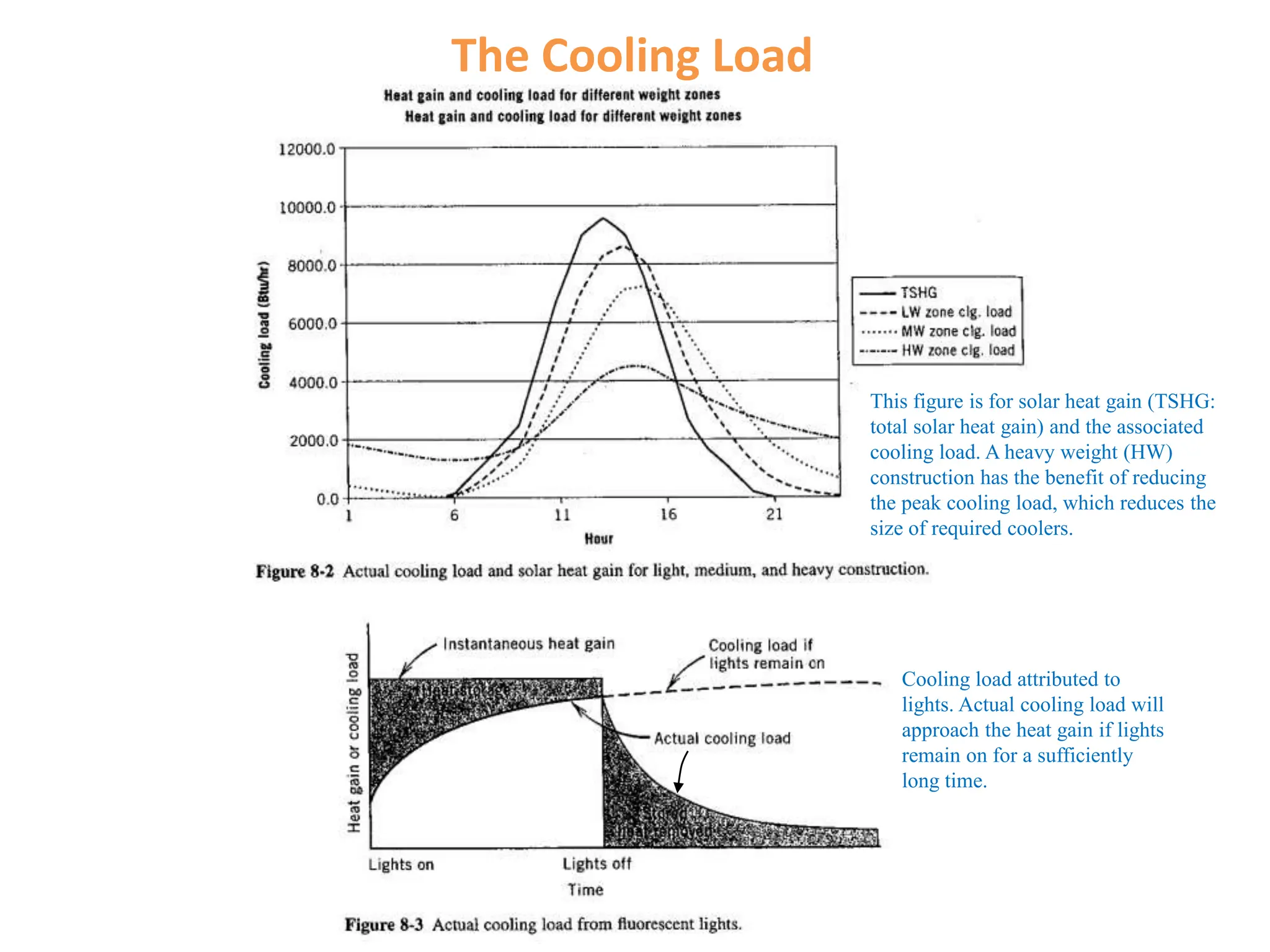
Cooling load is the rate at which energy must be removed from a space to maintain the desired temperature and humidity levels. It is determined by internal and external heat gains such as solar radiation, thermal radiation, convection, lights, people, and equipment, which are all transient in nature. The HvacLoadExplorer software uses the heat balance method to calculate cooling and heating loads by modeling a building as a hierarchy of zones, rooms, and heat gain elements and accounting for conduction, radiation, and other heat transfer processes.