SlideShare a Scribd company logo
Material Manufacturing
Asst. Professor
Sahib M.Mahdi
Cutting Temperature:
Almost all the work done in deformation the material to form the chip and move the chip and
the freshly cut work surface over the tool is converted into heat.
Figure (4) below shows the regions where the heat is primarily developed at the shear zone
(Q1), at the face tool [secondary zone (Q2)] and at tool workpiece interface (Q3).
Under normal conditions, the largest portion of
the work is done in forming the chip at the shear
plane (Q1), most the heat resulting from this
work remains in the chip is carried away by it,
while only a small percentage is conducted into
the workpiece.
(Q2) is the heat generated in the tool – chip
interface; it is due to friction between the chip
and the tool face.
(Q3) is the heat generated in tool – workpiece
interface, only a small percentage of the total
work done is converted into this heat.
Figure 4: Source of heat generation in
metal cutting.
That means:
Power = P = Fc . Vc = Q = Q1 + Q2,
where,Q_3 ≅ 0 which ignored since it is little
It is found that approximately (80%) of the generated heat is dissipated by the chip, (18%) by
the tool and the rest by the work surface. From this it clear that most of the heat in the metal
cutting is dissipated by the moving chip:
𝑸 = 𝑸𝑪 + 𝑸𝑻 + 𝑸𝑾
Where: QC = heat dissipated with chip.
QT = heat dissipated with tool.
QW = heat dissipated with workpiece.
The Temperature Rise:
So, the maximum temperature rise in the chip occurs where the material leaves the secondary
deformation zone and is given by:
𝑻𝒎𝒂𝒙 = 𝑻𝒐 + ∆𝑻𝟏 + ∆𝑻𝟐
Where: To = the initial workpiece temperature (℃)
∆T1 = temperature rise of the material passing through the primary zone (℃)
∆T2 = temperature rise of the material passing through the secondary zone (℃)
Cutting temperatures are important because high temperatures will causes:
 Reduce tool life.
 Produce hot chips that pose safety hazards to the machine operator, and,
 It can cause inaccuracies in workpart dimensions due to thermal expansion of the
work material.
This section will discuss the methods of calculating and measuring temperatures in machining
operations.
 There are several analytical methods to calculate estimates of cutting temperature.
 The most method, which was derived using experimental data for a variety of work
materials to establish parameter values for the resulting equation.
 The equation can be used to predict the increase in temperature at the tool–chip
interface during machining:
∆𝑻 =
𝟎. 𝟒 𝒖𝒄
𝝆𝑪
𝑽𝒄 . 𝒕𝒐
𝑲
𝟎.𝟑𝟑𝟑
Where:
∆T = mean temperature rise at the tool–chip interface, (o
C).
uc = specific energyin the operation, (N . m/mm3
or J/mm3
) .
Vc = cutting speed, (m/s);
to = chip thickness before the cut, (m); 𝛒 C = volumetric specific heat of the work
K = thermal diffusivity of the work material, (m2
/sec).
Example : Calculate the increase in temperature above ambient temperature of (20 o
C). Use
the given data:
Vc = 100 m/min, to = 0.50 mm.
In addition, the volumetric specific heat for the work material ( 𝛒C = 3.0 (10 -3
) J/mm3
.C, and,
Thermal diffusivity (K) = 50 (10 -6
) m2
/s (or 50 mm2
/sec).
Solution:
Cutting speed must be converted to mm/s:
Vc = (100 m/min) * (103
mm/m) / (60 s/min) = 1667 mm/s.
To compute the mean temperature rise:
∆𝑻 =
𝟎. 𝟒 𝒖𝒄
𝝆𝑪
𝑽𝒄 . 𝒕𝒐
𝑲
𝟎.𝟑𝟑𝟑
Tool Wear:
Tool wear causes the tool to lose its original shape, so that in time the tool ceases to cut
efficiently or even fails completely.
 Gradual wear occurs at two principal locations on a cutting tool: the top rake face and
the flank.
 Accordingly, two main types of tool wear can be distinguished: crater wear, flank wear
& nose wear, as illustrated in Figure (5).
Figure 5: Diagram of worn cutting tool, showing the principal locations and types of wear that occur
Crater wear:
It consists of a cavity in the rake face of the tool that forms and grows from the action of the
chip sliding against the surface. High stresses & temperatures characterize the tool–chip
contact interface, contributing to the wearing action.
Flank wear:
It occurs on the flank, or relief face, of the tool. It results from rubbing between the newly
generated work surface and the flank face adjacent to the cutting edge.
Nose radius wear:
This type occurs on the nose radius leading into the end cutting edge.
Tool Life:
Tool life may be defined as the effective cutting time between re-sharpenings. When the wear
reaches a certain value the tool is not capable of further cutting unless it is resharpened.
The general relationship of tool wear versus cutting time is shown in Figure (6).
Three regions can usually be identified in the curve.
 The first is the break-in period, in which the sharp cutting edge wears rapidly at the
beginning of its use within the first few minutes of cutting.
 The second is a uniform rate of wear called the steady-state wear region. It is shown as
a linear function of time.
 Finally, wear reaches a level at which the wear rate begins to accelerate. This marks
the beginning of the failure region, in which cutting temperatures are higher, and the
general efficiency of the machining process is reduced.
Figure 6: Tool wear as a function of cutting time and cutting speed.
 Taylor Tool Life Equation:
It has been shown that the relationship between the tool live and the cutting speed can be
represented by the following equation [figure (7)]:
𝑽 . 𝑻𝒏
= 𝑪
Figure 7: Natural log–log plot of cutting speed versus
tool life.
𝑽 . 𝑻𝒏
= 𝑪
• T = tool life (min); and,
• ( n ) and ( C ) are parameters whose
values depend on feed, depth of cut,
work material, tooling (material in
particular), and the tool life criterion
used (flank wear value, such as 0.5
mm).
Where:
• Vc = cutting speed (m/min);
An expanded version of Taylor Equation can be formulated to include the effects of feed,
depth (width) of cut, and even work material hardness:
𝑽 . 𝑻𝒏
. 𝒇𝒎
. 𝒃𝒑
. 𝑯𝒒
= 𝑪
Where: f = feed, mm (in); b = depth (width) of cut, mm (in); H = hardness, expressed in an
appropriate hardness scale; [ m, p, and q ] are exponents whose values are experimentally
determined for the conditions of the operation; C = constant.
To reduce these problems and make the scope of the equation more manageable, some of the
terms are usually eliminated. For example, omitting depth and hardness reduces Equation to
the following:
𝑽 . 𝑻𝒏
. 𝒇𝒎
= 𝑪
Cutting Fluids:
A cutting fluid is any liquid or gas that is applied directly to the machining operation to
improve cutting performance. Cutting fluids address two main problems:
(1) Heat generation at the shear zone and friction zone, and,
(2) Friction at the tool–chip and tool–work interfaces.
This will work to:
(1) Removing heat and reducing friction cause to prolong the tool life.
(2) Washing away chips (especially in grinding and milling).
(3) Reducing cutting forces and power requirements.
(4) Reducing the temperature of the work-part for easier handling.
(5) Improving dimensional stability of the work-part & improving surface finish.
(6) Protect the newly machined surface from corrosion.
Cutting Fluid Functions:
There are two general categories of cutting fluids, corresponding to the two main problems
they are designed to address: coolants and lubricants.
Coolants:
They are chemical fluids (chemicals in a water solution). The dissolved chemicals include
compounds of sulfur, chlorine, and phosphorus, plus wetting agents. The chemicals are
intended to provide some degree of lubrication to the solution.
The capacity of a cutting fluid to reduce temperatures in machining depends on its thermal
properties. Specific heat and thermal conductivity are the most important properties.
Water has high specific heat and thermal conductivity relative to other liquids, which is why
water is used as the base in coolant-type cutting fluids.
Lubricants:
They are usually oil-based fluids (because oils possess good lubricating qualities) formulated
to reduce friction at the tool–chip and tool–work interfaces.
Lubricant-type cutting fluids are most effective at lower cutting speeds. They tend to lose
their effectiveness at high speeds (above about 120 m/min) because the motion of the chip at
these speeds prevents the cutting fluid from reaching the tool–chip interface.
Kind of Cutting Fluid: cutting fluids may be classified as:
(1) Gases (Air, CO2). (2) Water solution. (3) Oils. (4) Waxes.
Q1: Tool life tests on a lathe have resulted in the following data: (1) at a cutting speed of (
160 m/min ), the tool life was ( 5 min ); (2) at a cutting speed of ( 100 m/min ), the tool life was
( 41 min. ). Determine the parameters ( n and C ) in the Taylor tool life equation.
Solution:
Using the Taylor tool life equation:
𝑽 . 𝑻𝒏
= 𝑪
With the following data, [ V = 160 m/min. and T = 5 min.], we can obtain the following
equation:
Q2: The following equation for tool life was obtained for H. S. S. tool, which is:
𝑽 . 𝑻𝟎.𝟏𝟑
. 𝒇𝟎.𝟔
. 𝒅𝟎.𝟑
= 𝑪
A tool life of ( 60 min. ) was obtained by using the following cutting condition, which are:
V = 40 m/min., f = 0.25 mm., and d = 2 mm.
Calculate the effect on the tool life if the speed ( V ), feed ( f ) and the depth ( d ) are all
together increased by ( 25 % ), and calculate also the effect of tool life if each of the above
parameter ( V, f and d ) are individually increased by ( 25 % ).
Solution:
From the above given data, the constant ( C ) can be obtained to be:
𝑽 . 𝑻𝟎.𝟏𝟑
. 𝒇𝟎.𝟔
. 𝒅𝟎.𝟑
= 𝑪
𝑪 = 𝟒𝟎 ∗ 𝟔𝟎𝟎.𝟏𝟑
∗ 𝟎. 𝟐𝟓𝟎.𝟔
∗ 𝟐𝟎.𝟑
= 𝟑𝟔. 𝟒𝟐
In this problem, we have two cases:
Case ( 1 ):
the first case when each of following parameters are increased all together by ( 25 % ), that
means the cutting speed ( V ) is increased by ( 25 % ) to become:
𝑽𝟏 = 𝟒𝟎 ∗ 𝟏. 𝟐𝟓 = 𝟓𝟎 𝒎 𝒎𝒊𝒏.
The feeding ( f ) is increased by ( 25 % ), to become:
𝒇𝟏 = 𝟎. 𝟐𝟓 ∗ 𝟏. 𝟐𝟓 = 𝟎. 𝟑𝟏𝟐𝟓 𝒎𝒎
And the depth of cutting ( d ) is also become:
𝒅𝟏 = 𝟐 ∗ 𝟏. 𝟐𝟓 = 𝟐. 𝟓 𝒎𝒎
Substituting, the above values in the tool life equation to obtain:
𝑽 . 𝑻𝟎.𝟏𝟑
. 𝒇𝟎.𝟔
. 𝒅𝟎.𝟑
= 𝑪
𝟓𝟎 ∗ 𝑻𝟎.𝟏𝟑
∗ 𝟎. 𝟑𝟏𝟐𝟓𝟎.𝟔
∗ 𝟐. 𝟓𝟎.𝟑
= 𝟑𝟔. 𝟒𝟐
𝑻𝟎.𝟏𝟑
=
𝟑𝟔. 𝟒𝟐
𝟑𝟐. 𝟗
= 𝟏. 𝟏𝟎𝟔
𝑻 = 𝟐. 𝟏𝟕 𝒎𝒊𝒏.
Case ( 2 ):
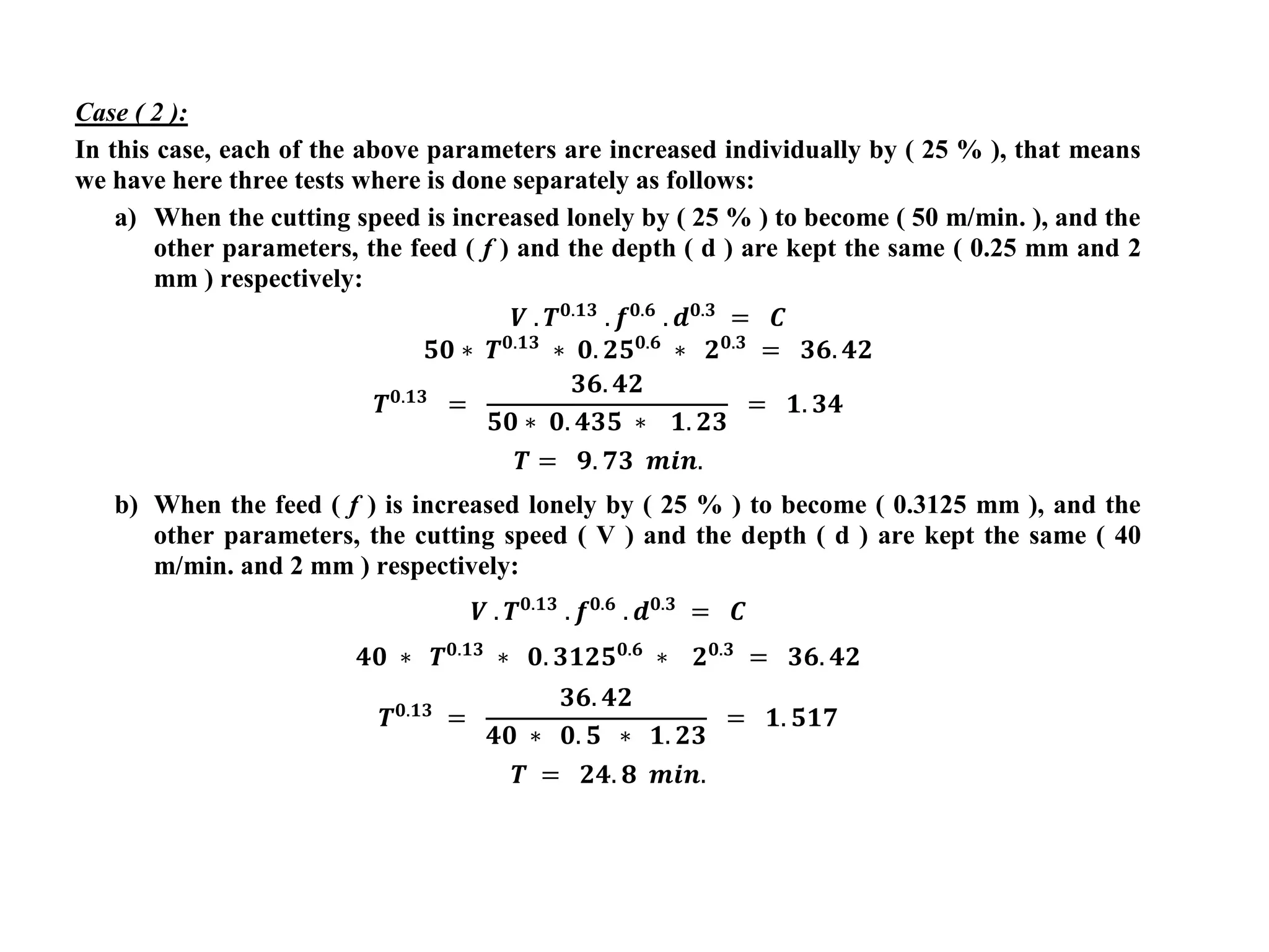
In this case, each of the above parameters are increased individually by ( 25 % ), that means
we have here three tests where is done separately as follows:
a) When the cutting speed is increased lonely by ( 25 % ) to become ( 50 m/min. ), and the
other parameters, the feed ( f ) and the depth ( d ) are kept the same ( 0.25 mm and 2
mm ) respectively:
𝑽 . 𝑻𝟎.𝟏𝟑
. 𝒇𝟎.𝟔
. 𝒅𝟎.𝟑
= 𝑪
𝟓𝟎 ∗ 𝑻𝟎.𝟏𝟑
∗ 𝟎. 𝟐𝟓𝟎.𝟔
∗ 𝟐𝟎.𝟑
= 𝟑𝟔. 𝟒𝟐
𝑻𝟎.𝟏𝟑
=
𝟑𝟔. 𝟒𝟐
𝟓𝟎 ∗ 𝟎. 𝟒𝟑𝟓 ∗ 𝟏. 𝟐𝟑
= 𝟏. 𝟑𝟒
𝑻 = 𝟗. 𝟕𝟑 𝒎𝒊𝒏.
b) When the feed ( f ) is increased lonely by ( 25 % ) to become ( 0.3125 mm ), and the
other parameters, the cutting speed ( V ) and the depth ( d ) are kept the same ( 40
m/min. and 2 mm ) respectively:
𝑽 . 𝑻𝟎.𝟏𝟑
. 𝒇𝟎.𝟔
. 𝒅𝟎.𝟑
= 𝑪
𝟒𝟎 ∗ 𝑻𝟎.𝟏𝟑
∗ 𝟎. 𝟑𝟏𝟐𝟓𝟎.𝟔
∗ 𝟐𝟎.𝟑
= 𝟑𝟔. 𝟒𝟐
𝑻𝟎.𝟏𝟑
=
𝟑𝟔. 𝟒𝟐
𝟒𝟎 ∗ 𝟎. 𝟓 ∗ 𝟏. 𝟐𝟑
= 𝟏. 𝟓𝟏𝟕
𝑻 = 𝟐𝟒. 𝟖 𝒎𝒊𝒏.
c) When the depth ( d ) is increased lonely by ( 25 % ) to become ( 2.5 mm ), and the other
parameters, the cutting speed ( V ) and the depth ( f ) are kept the same ( 40 m/min.
and 0.25 mm ) respectively:
𝑽 . 𝑻𝟎.𝟏𝟑
. 𝒇𝟎.𝟔
. 𝒅𝟎.𝟑
= 𝑪
a) When the depth ( d ) is increased lonely by ( 25 % ) to become ( 2.5 mm ), and the other
parameters, the cutting speed ( V ) and the depth ( f ) are kept the same ( 40 m/min.
and 0.25 mm ) respectively:
𝑽 . 𝑻𝟎.𝟏𝟑
. 𝒇𝟎.𝟔
. 𝒅𝟎.𝟑
= 𝑪
𝟒𝟎 ∗ 𝑻𝟎.𝟏𝟑
∗ 𝟎. 𝟐𝟓𝟎.𝟔
∗ 𝟐. 𝟓𝟎.𝟑
= 𝟑𝟔. 𝟒𝟐
𝑻𝟎.𝟏𝟑
=
𝟑𝟔. 𝟒𝟐
𝟒𝟎 ∗ 𝟎. 𝟒𝟑𝟓 ∗ 𝟏. 𝟑
= 𝟏. 𝟔𝟏
𝑻 = 𝟑𝟗. 𝟏𝟓 𝒎𝒊𝒏.
It appears that the significant effect on the tool life when all of these parameters together are
increased by ( 25 % ) to reduce the tool life to ( 2.17 min. ).
But, when each of these parameters are increased individually, the most significant effect is
utilized when the cutting speed is increased by ( 25 % ) to reduce the tool life to ( 9.73 min.),
the lowest effect is obtained when the depth ( d ) is increased by ( 25 % ) to reduce the tool life
to ( 39.15 min. ).

More Related Content

Similar to tool life calcu.pdf

Tool life by amit hazari
Tool life by amit hazariTool life by amit hazari
Tool life by amit hazari
Amit hazari
 
Economics of turning process
Economics of turning processEconomics of turning process
Economics of turning process
Amr El-ashmony
 
heat in metal cutting
heat in metal cuttingheat in metal cutting
heat in metal cutting
Rania Atia
 
Problems of Heat, Mass and Momentum Transfer in Manufacturing Processes: A Br...
Problems of Heat, Mass and Momentum Transfer in Manufacturing Processes: A Br...Problems of Heat, Mass and Momentum Transfer in Manufacturing Processes: A Br...
Problems of Heat, Mass and Momentum Transfer in Manufacturing Processes: A Br...
drboon
 
Z01226158164
Z01226158164Z01226158164
Z01226158164
IOSR Journals
 
International Journal of Engineering Research and Development (IJERD)
International Journal of Engineering Research and Development (IJERD)International Journal of Engineering Research and Development (IJERD)
International Journal of Engineering Research and Development (IJERD)
IJERD Editor
 
Study the Chip Tool Interactions & Tool Life in Plain Turining with High Velo...
Study the Chip Tool Interactions & Tool Life in Plain Turining with High Velo...Study the Chip Tool Interactions & Tool Life in Plain Turining with High Velo...
Study the Chip Tool Interactions & Tool Life in Plain Turining with High Velo...
IJERA Editor
 
Kumar&Satodia_AUE863_PPT
Kumar&Satodia_AUE863_PPTKumar&Satodia_AUE863_PPT
Kumar&Satodia_AUE863_PPTShyamal Satodia
 
Kumar&Satodia_AUE867_P02
Kumar&Satodia_AUE867_P02Kumar&Satodia_AUE867_P02
Kumar&Satodia_AUE867_P02Varun Singh
 
Stress distribution in grinding by finite element analysis
Stress distribution in grinding by finite element analysisStress distribution in grinding by finite element analysis
Stress distribution in grinding by finite element analysis
Bijoy Das
 
STRESS DISTRIBUTION IN GRINDING BY FINITE ELEMENT ANALYSIS
STRESS DISTRIBUTION IN GRINDING BY FINITE ELEMENT ANALYSISSTRESS DISTRIBUTION IN GRINDING BY FINITE ELEMENT ANALYSIS
STRESS DISTRIBUTION IN GRINDING BY FINITE ELEMENT ANALYSIS
Bijoy Das
 
IRJET- Analysis of Single Point Cutting Tool
IRJET- Analysis of Single Point Cutting ToolIRJET- Analysis of Single Point Cutting Tool
IRJET- Analysis of Single Point Cutting Tool
IRJET Journal
 
Design & Development of Injection Mold Using Flow Analysis and Higher End Des...
Design & Development of Injection Mold Using Flow Analysis and Higher End Des...Design & Development of Injection Mold Using Flow Analysis and Higher End Des...
Design & Development of Injection Mold Using Flow Analysis and Higher End Des...
paperpublications3
 
International Journal of Computational Engineering Research (IJCER)
International Journal of Computational Engineering Research (IJCER) International Journal of Computational Engineering Research (IJCER)
International Journal of Computational Engineering Research (IJCER)
ijceronline
 
06 tool life
06 tool life06 tool life
06 tool life
M Siva Kumar
 
Automatic design of technological process of forging
Automatic design of technological process of forgingAutomatic design of technological process of forging
Automatic design of technological process of forgingIAEME Publication
 
CH-5-6 Merchant Theory &Temperature in Cutting.pdf
CH-5-6 Merchant Theory &Temperature in Cutting.pdfCH-5-6 Merchant Theory &Temperature in Cutting.pdf
CH-5-6 Merchant Theory &Temperature in Cutting.pdf
TemesgenErena
 
TRIBOLOGICAL STUDY OF CUTTING TOOLS.pptx
TRIBOLOGICAL STUDY OF CUTTING TOOLS.pptxTRIBOLOGICAL STUDY OF CUTTING TOOLS.pptx
TRIBOLOGICAL STUDY OF CUTTING TOOLS.pptx
Mahadev Lakshmi
 
Model for prediction of temperature distribution in workpiece for surface gri...
Model for prediction of temperature distribution in workpiece for surface gri...Model for prediction of temperature distribution in workpiece for surface gri...
Model for prediction of temperature distribution in workpiece for surface gri...iaemedu
 
Model for prediction of temperature distribution in workpiece for surface gri...
Model for prediction of temperature distribution in workpiece for surface gri...Model for prediction of temperature distribution in workpiece for surface gri...
Model for prediction of temperature distribution in workpiece for surface gri...IAEME Publication
 

Similar to tool life calcu.pdf (20)

Tool life by amit hazari
Tool life by amit hazariTool life by amit hazari
Tool life by amit hazari
 
Economics of turning process
Economics of turning processEconomics of turning process
Economics of turning process
 
heat in metal cutting
heat in metal cuttingheat in metal cutting
heat in metal cutting
 
Problems of Heat, Mass and Momentum Transfer in Manufacturing Processes: A Br...
Problems of Heat, Mass and Momentum Transfer in Manufacturing Processes: A Br...Problems of Heat, Mass and Momentum Transfer in Manufacturing Processes: A Br...
Problems of Heat, Mass and Momentum Transfer in Manufacturing Processes: A Br...
 
Z01226158164
Z01226158164Z01226158164
Z01226158164
 
International Journal of Engineering Research and Development (IJERD)
International Journal of Engineering Research and Development (IJERD)International Journal of Engineering Research and Development (IJERD)
International Journal of Engineering Research and Development (IJERD)
 
Study the Chip Tool Interactions & Tool Life in Plain Turining with High Velo...
Study the Chip Tool Interactions & Tool Life in Plain Turining with High Velo...Study the Chip Tool Interactions & Tool Life in Plain Turining with High Velo...
Study the Chip Tool Interactions & Tool Life in Plain Turining with High Velo...
 
Kumar&Satodia_AUE863_PPT
Kumar&Satodia_AUE863_PPTKumar&Satodia_AUE863_PPT
Kumar&Satodia_AUE863_PPT
 
Kumar&Satodia_AUE867_P02
Kumar&Satodia_AUE867_P02Kumar&Satodia_AUE867_P02
Kumar&Satodia_AUE867_P02
 
Stress distribution in grinding by finite element analysis
Stress distribution in grinding by finite element analysisStress distribution in grinding by finite element analysis
Stress distribution in grinding by finite element analysis
 
STRESS DISTRIBUTION IN GRINDING BY FINITE ELEMENT ANALYSIS
STRESS DISTRIBUTION IN GRINDING BY FINITE ELEMENT ANALYSISSTRESS DISTRIBUTION IN GRINDING BY FINITE ELEMENT ANALYSIS
STRESS DISTRIBUTION IN GRINDING BY FINITE ELEMENT ANALYSIS
 
IRJET- Analysis of Single Point Cutting Tool
IRJET- Analysis of Single Point Cutting ToolIRJET- Analysis of Single Point Cutting Tool
IRJET- Analysis of Single Point Cutting Tool
 
Design & Development of Injection Mold Using Flow Analysis and Higher End Des...
Design & Development of Injection Mold Using Flow Analysis and Higher End Des...Design & Development of Injection Mold Using Flow Analysis and Higher End Des...
Design & Development of Injection Mold Using Flow Analysis and Higher End Des...
 
International Journal of Computational Engineering Research (IJCER)
International Journal of Computational Engineering Research (IJCER) International Journal of Computational Engineering Research (IJCER)
International Journal of Computational Engineering Research (IJCER)
 
06 tool life
06 tool life06 tool life
06 tool life
 
Automatic design of technological process of forging
Automatic design of technological process of forgingAutomatic design of technological process of forging
Automatic design of technological process of forging
 
CH-5-6 Merchant Theory &Temperature in Cutting.pdf
CH-5-6 Merchant Theory &Temperature in Cutting.pdfCH-5-6 Merchant Theory &Temperature in Cutting.pdf
CH-5-6 Merchant Theory &Temperature in Cutting.pdf
 
TRIBOLOGICAL STUDY OF CUTTING TOOLS.pptx
TRIBOLOGICAL STUDY OF CUTTING TOOLS.pptxTRIBOLOGICAL STUDY OF CUTTING TOOLS.pptx
TRIBOLOGICAL STUDY OF CUTTING TOOLS.pptx
 
Model for prediction of temperature distribution in workpiece for surface gri...
Model for prediction of temperature distribution in workpiece for surface gri...Model for prediction of temperature distribution in workpiece for surface gri...
Model for prediction of temperature distribution in workpiece for surface gri...
 
Model for prediction of temperature distribution in workpiece for surface gri...
Model for prediction of temperature distribution in workpiece for surface gri...Model for prediction of temperature distribution in workpiece for surface gri...
Model for prediction of temperature distribution in workpiece for surface gri...
 

More from TauqeerIqbal6

CIP Usman Butt.pptx
CIP Usman Butt.pptxCIP Usman Butt.pptx
CIP Usman Butt.pptx
TauqeerIqbal6
 
dynamics-140122001630-phpapp02.pdf
dynamics-140122001630-phpapp02.pdfdynamics-140122001630-phpapp02.pdf
dynamics-140122001630-phpapp02.pdf
TauqeerIqbal6
 
4-Rim-University-industry-linkages-presentation-reviewed-v2.pptx
4-Rim-University-industry-linkages-presentation-reviewed-v2.pptx4-Rim-University-industry-linkages-presentation-reviewed-v2.pptx
4-Rim-University-industry-linkages-presentation-reviewed-v2.pptx
TauqeerIqbal6
 
Current Issue Presentation 19-10-21.pptx
Current Issue Presentation 19-10-21.pptxCurrent Issue Presentation 19-10-21.pptx
Current Issue Presentation 19-10-21.pptx
TauqeerIqbal6
 
CIP.pptx
CIP.pptxCIP.pptx
CIP.pptx
TauqeerIqbal6
 
CIP.pptx
CIP.pptxCIP.pptx
CIP.pptx
TauqeerIqbal6
 
Artificial Intelligence.pdf
Artificial Intelligence.pdfArtificial Intelligence.pdf
Artificial Intelligence.pdf
TauqeerIqbal6
 
9th c4.pdf
9th c4.pdf9th c4.pdf
9th c4.pdf
TauqeerIqbal6
 
Thought of The Day.pptx
Thought of The Day.pptxThought of The Day.pptx
Thought of The Day.pptx
TauqeerIqbal6
 
CIP.pptx
CIP.pptxCIP.pptx
CIP.pptx
TauqeerIqbal6
 
9th c4.pdf
9th c4.pdf9th c4.pdf
9th c4.pdf
TauqeerIqbal6
 
Zymography
ZymographyZymography
Zymography
TauqeerIqbal6
 
Chapter 7 questions
Chapter 7 questionsChapter 7 questions
Chapter 7 questions
TauqeerIqbal6
 

More from TauqeerIqbal6 (13)

CIP Usman Butt.pptx
CIP Usman Butt.pptxCIP Usman Butt.pptx
CIP Usman Butt.pptx
 
dynamics-140122001630-phpapp02.pdf
dynamics-140122001630-phpapp02.pdfdynamics-140122001630-phpapp02.pdf
dynamics-140122001630-phpapp02.pdf
 
4-Rim-University-industry-linkages-presentation-reviewed-v2.pptx
4-Rim-University-industry-linkages-presentation-reviewed-v2.pptx4-Rim-University-industry-linkages-presentation-reviewed-v2.pptx
4-Rim-University-industry-linkages-presentation-reviewed-v2.pptx
 
Current Issue Presentation 19-10-21.pptx
Current Issue Presentation 19-10-21.pptxCurrent Issue Presentation 19-10-21.pptx
Current Issue Presentation 19-10-21.pptx
 
CIP.pptx
CIP.pptxCIP.pptx
CIP.pptx
 
CIP.pptx
CIP.pptxCIP.pptx
CIP.pptx
 
Artificial Intelligence.pdf
Artificial Intelligence.pdfArtificial Intelligence.pdf
Artificial Intelligence.pdf
 
9th c4.pdf
9th c4.pdf9th c4.pdf
9th c4.pdf
 
Thought of The Day.pptx
Thought of The Day.pptxThought of The Day.pptx
Thought of The Day.pptx
 
CIP.pptx
CIP.pptxCIP.pptx
CIP.pptx
 
9th c4.pdf
9th c4.pdf9th c4.pdf
9th c4.pdf
 
Zymography
ZymographyZymography
Zymography
 
Chapter 7 questions
Chapter 7 questionsChapter 7 questions
Chapter 7 questions
 

Recently uploaded

Digital Tools and AI for Teaching Learning and Research
Digital Tools and AI for Teaching Learning and ResearchDigital Tools and AI for Teaching Learning and Research
Digital Tools and AI for Teaching Learning and Research
Vikramjit Singh
 
PART A. Introduction to Costumer Service
PART A. Introduction to Costumer ServicePART A. Introduction to Costumer Service
PART A. Introduction to Costumer Service
PedroFerreira53928
 
How to Break the cycle of negative Thoughts
How to Break the cycle of negative ThoughtsHow to Break the cycle of negative Thoughts
How to Break the cycle of negative Thoughts
Col Mukteshwar Prasad
 
Additional Benefits for Employee Website.pdf
Additional Benefits for Employee Website.pdfAdditional Benefits for Employee Website.pdf
Additional Benefits for Employee Website.pdf
joachimlavalley1
 
The French Revolution Class 9 Study Material pdf free download
The French Revolution Class 9 Study Material pdf free downloadThe French Revolution Class 9 Study Material pdf free download
The French Revolution Class 9 Study Material pdf free download
Vivekanand Anglo Vedic Academy
 
aaaaaaaaaaaaaaaaaaaaaaaaaaaaaaaaaaaaaaaaa
aaaaaaaaaaaaaaaaaaaaaaaaaaaaaaaaaaaaaaaaaaaaaaaaaaaaaaaaaaaaaaaaaaaaaaaaaaaaaaaaaa
aaaaaaaaaaaaaaaaaaaaaaaaaaaaaaaaaaaaaaaaa
siemaillard
 
Students, digital devices and success - Andreas Schleicher - 27 May 2024..pptx
Students, digital devices and success - Andreas Schleicher - 27 May 2024..pptxStudents, digital devices and success - Andreas Schleicher - 27 May 2024..pptx
Students, digital devices and success - Andreas Schleicher - 27 May 2024..pptx
EduSkills OECD
 
CLASS 11 CBSE B.St Project AIDS TO TRADE - INSURANCE
CLASS 11 CBSE B.St Project AIDS TO TRADE - INSURANCECLASS 11 CBSE B.St Project AIDS TO TRADE - INSURANCE
CLASS 11 CBSE B.St Project AIDS TO TRADE - INSURANCE
BhavyaRajput3
 
Supporting (UKRI) OA monographs at Salford.pptx
Supporting (UKRI) OA monographs at Salford.pptxSupporting (UKRI) OA monographs at Salford.pptx
Supporting (UKRI) OA monographs at Salford.pptx
Jisc
 
Sha'Carri Richardson Presentation 202345
Sha'Carri Richardson Presentation 202345Sha'Carri Richardson Presentation 202345
Sha'Carri Richardson Presentation 202345
beazzy04
 
Chapter 3 - Islamic Banking Products and Services.pptx
Chapter 3 - Islamic Banking Products and Services.pptxChapter 3 - Islamic Banking Products and Services.pptx
Chapter 3 - Islamic Banking Products and Services.pptx
Mohd Adib Abd Muin, Senior Lecturer at Universiti Utara Malaysia
 
Welcome to TechSoup New Member Orientation and Q&A (May 2024).pdf
Welcome to TechSoup   New Member Orientation and Q&A (May 2024).pdfWelcome to TechSoup   New Member Orientation and Q&A (May 2024).pdf
Welcome to TechSoup New Member Orientation and Q&A (May 2024).pdf
TechSoup
 
How libraries can support authors with open access requirements for UKRI fund...
How libraries can support authors with open access requirements for UKRI fund...How libraries can support authors with open access requirements for UKRI fund...
How libraries can support authors with open access requirements for UKRI fund...
Jisc
 
Model Attribute Check Company Auto Property
Model Attribute  Check Company Auto PropertyModel Attribute  Check Company Auto Property
Model Attribute Check Company Auto Property
Celine George
 
GIÁO ÁN DẠY THÊM (KẾ HOẠCH BÀI BUỔI 2) - TIẾNG ANH 8 GLOBAL SUCCESS (2 CỘT) N...
GIÁO ÁN DẠY THÊM (KẾ HOẠCH BÀI BUỔI 2) - TIẾNG ANH 8 GLOBAL SUCCESS (2 CỘT) N...GIÁO ÁN DẠY THÊM (KẾ HOẠCH BÀI BUỔI 2) - TIẾNG ANH 8 GLOBAL SUCCESS (2 CỘT) N...
GIÁO ÁN DẠY THÊM (KẾ HOẠCH BÀI BUỔI 2) - TIẾNG ANH 8 GLOBAL SUCCESS (2 CỘT) N...
Nguyen Thanh Tu Collection
 
aaaaaaaaaaaaaaaaaaaaaaaaaaaaaaaaaaaaaaaaaaaaaaaaaaaaaaa
aaaaaaaaaaaaaaaaaaaaaaaaaaaaaaaaaaaaaaaaaaaaaaaaaaaaaaaaaaaaaaaaaaaaaaaaaaaaaaaaaaaaaaaaaaaaaaaaaaaaaaaaaaaaaa
aaaaaaaaaaaaaaaaaaaaaaaaaaaaaaaaaaaaaaaaaaaaaaaaaaaaaaa
siemaillard
 
Unit 8 - Information and Communication Technology (Paper I).pdf
Unit 8 - Information and Communication Technology (Paper I).pdfUnit 8 - Information and Communication Technology (Paper I).pdf
Unit 8 - Information and Communication Technology (Paper I).pdf
Thiyagu K
 
1.4 modern child centered education - mahatma gandhi-2.pptx
1.4 modern child centered education - mahatma gandhi-2.pptx1.4 modern child centered education - mahatma gandhi-2.pptx
1.4 modern child centered education - mahatma gandhi-2.pptx
JosvitaDsouza2
 
Unit 2- Research Aptitude (UGC NET Paper I).pdf
Unit 2- Research Aptitude (UGC NET Paper I).pdfUnit 2- Research Aptitude (UGC NET Paper I).pdf
Unit 2- Research Aptitude (UGC NET Paper I).pdf
Thiyagu K
 
The Roman Empire A Historical Colossus.pdf
The Roman Empire A Historical Colossus.pdfThe Roman Empire A Historical Colossus.pdf
The Roman Empire A Historical Colossus.pdf
kaushalkr1407
 

Recently uploaded (20)

Digital Tools and AI for Teaching Learning and Research
Digital Tools and AI for Teaching Learning and ResearchDigital Tools and AI for Teaching Learning and Research
Digital Tools and AI for Teaching Learning and Research
 
PART A. Introduction to Costumer Service
PART A. Introduction to Costumer ServicePART A. Introduction to Costumer Service
PART A. Introduction to Costumer Service
 
How to Break the cycle of negative Thoughts
How to Break the cycle of negative ThoughtsHow to Break the cycle of negative Thoughts
How to Break the cycle of negative Thoughts
 
Additional Benefits for Employee Website.pdf
Additional Benefits for Employee Website.pdfAdditional Benefits for Employee Website.pdf
Additional Benefits for Employee Website.pdf
 
The French Revolution Class 9 Study Material pdf free download
The French Revolution Class 9 Study Material pdf free downloadThe French Revolution Class 9 Study Material pdf free download
The French Revolution Class 9 Study Material pdf free download
 
aaaaaaaaaaaaaaaaaaaaaaaaaaaaaaaaaaaaaaaaa
aaaaaaaaaaaaaaaaaaaaaaaaaaaaaaaaaaaaaaaaaaaaaaaaaaaaaaaaaaaaaaaaaaaaaaaaaaaaaaaaaa
aaaaaaaaaaaaaaaaaaaaaaaaaaaaaaaaaaaaaaaaa
 
Students, digital devices and success - Andreas Schleicher - 27 May 2024..pptx
Students, digital devices and success - Andreas Schleicher - 27 May 2024..pptxStudents, digital devices and success - Andreas Schleicher - 27 May 2024..pptx
Students, digital devices and success - Andreas Schleicher - 27 May 2024..pptx
 
CLASS 11 CBSE B.St Project AIDS TO TRADE - INSURANCE
CLASS 11 CBSE B.St Project AIDS TO TRADE - INSURANCECLASS 11 CBSE B.St Project AIDS TO TRADE - INSURANCE
CLASS 11 CBSE B.St Project AIDS TO TRADE - INSURANCE
 
Supporting (UKRI) OA monographs at Salford.pptx
Supporting (UKRI) OA monographs at Salford.pptxSupporting (UKRI) OA monographs at Salford.pptx
Supporting (UKRI) OA monographs at Salford.pptx
 
Sha'Carri Richardson Presentation 202345
Sha'Carri Richardson Presentation 202345Sha'Carri Richardson Presentation 202345
Sha'Carri Richardson Presentation 202345
 
Chapter 3 - Islamic Banking Products and Services.pptx
Chapter 3 - Islamic Banking Products and Services.pptxChapter 3 - Islamic Banking Products and Services.pptx
Chapter 3 - Islamic Banking Products and Services.pptx
 
Welcome to TechSoup New Member Orientation and Q&A (May 2024).pdf
Welcome to TechSoup   New Member Orientation and Q&A (May 2024).pdfWelcome to TechSoup   New Member Orientation and Q&A (May 2024).pdf
Welcome to TechSoup New Member Orientation and Q&A (May 2024).pdf
 
How libraries can support authors with open access requirements for UKRI fund...
How libraries can support authors with open access requirements for UKRI fund...How libraries can support authors with open access requirements for UKRI fund...
How libraries can support authors with open access requirements for UKRI fund...
 
Model Attribute Check Company Auto Property
Model Attribute  Check Company Auto PropertyModel Attribute  Check Company Auto Property
Model Attribute Check Company Auto Property
 
GIÁO ÁN DẠY THÊM (KẾ HOẠCH BÀI BUỔI 2) - TIẾNG ANH 8 GLOBAL SUCCESS (2 CỘT) N...
GIÁO ÁN DẠY THÊM (KẾ HOẠCH BÀI BUỔI 2) - TIẾNG ANH 8 GLOBAL SUCCESS (2 CỘT) N...GIÁO ÁN DẠY THÊM (KẾ HOẠCH BÀI BUỔI 2) - TIẾNG ANH 8 GLOBAL SUCCESS (2 CỘT) N...
GIÁO ÁN DẠY THÊM (KẾ HOẠCH BÀI BUỔI 2) - TIẾNG ANH 8 GLOBAL SUCCESS (2 CỘT) N...
 
aaaaaaaaaaaaaaaaaaaaaaaaaaaaaaaaaaaaaaaaaaaaaaaaaaaaaaa
aaaaaaaaaaaaaaaaaaaaaaaaaaaaaaaaaaaaaaaaaaaaaaaaaaaaaaaaaaaaaaaaaaaaaaaaaaaaaaaaaaaaaaaaaaaaaaaaaaaaaaaaaaaaaa
aaaaaaaaaaaaaaaaaaaaaaaaaaaaaaaaaaaaaaaaaaaaaaaaaaaaaaa
 
Unit 8 - Information and Communication Technology (Paper I).pdf
Unit 8 - Information and Communication Technology (Paper I).pdfUnit 8 - Information and Communication Technology (Paper I).pdf
Unit 8 - Information and Communication Technology (Paper I).pdf
 
1.4 modern child centered education - mahatma gandhi-2.pptx
1.4 modern child centered education - mahatma gandhi-2.pptx1.4 modern child centered education - mahatma gandhi-2.pptx
1.4 modern child centered education - mahatma gandhi-2.pptx
 
Unit 2- Research Aptitude (UGC NET Paper I).pdf
Unit 2- Research Aptitude (UGC NET Paper I).pdfUnit 2- Research Aptitude (UGC NET Paper I).pdf
Unit 2- Research Aptitude (UGC NET Paper I).pdf
 
The Roman Empire A Historical Colossus.pdf
The Roman Empire A Historical Colossus.pdfThe Roman Empire A Historical Colossus.pdf
The Roman Empire A Historical Colossus.pdf
 

tool life calcu.pdf

  • 2. Cutting Temperature: Almost all the work done in deformation the material to form the chip and move the chip and the freshly cut work surface over the tool is converted into heat. Figure (4) below shows the regions where the heat is primarily developed at the shear zone (Q1), at the face tool [secondary zone (Q2)] and at tool workpiece interface (Q3). Under normal conditions, the largest portion of the work is done in forming the chip at the shear plane (Q1), most the heat resulting from this work remains in the chip is carried away by it, while only a small percentage is conducted into the workpiece. (Q2) is the heat generated in the tool – chip interface; it is due to friction between the chip and the tool face. (Q3) is the heat generated in tool – workpiece interface, only a small percentage of the total work done is converted into this heat. Figure 4: Source of heat generation in metal cutting. That means: Power = P = Fc . Vc = Q = Q1 + Q2, where,Q_3 ≅ 0 which ignored since it is little
  • 3. It is found that approximately (80%) of the generated heat is dissipated by the chip, (18%) by the tool and the rest by the work surface. From this it clear that most of the heat in the metal cutting is dissipated by the moving chip: 𝑸 = 𝑸𝑪 + 𝑸𝑻 + 𝑸𝑾 Where: QC = heat dissipated with chip. QT = heat dissipated with tool. QW = heat dissipated with workpiece. The Temperature Rise: So, the maximum temperature rise in the chip occurs where the material leaves the secondary deformation zone and is given by: 𝑻𝒎𝒂𝒙 = 𝑻𝒐 + ∆𝑻𝟏 + ∆𝑻𝟐 Where: To = the initial workpiece temperature (℃) ∆T1 = temperature rise of the material passing through the primary zone (℃) ∆T2 = temperature rise of the material passing through the secondary zone (℃) Cutting temperatures are important because high temperatures will causes:  Reduce tool life.  Produce hot chips that pose safety hazards to the machine operator, and,  It can cause inaccuracies in workpart dimensions due to thermal expansion of the work material.
  • 4. This section will discuss the methods of calculating and measuring temperatures in machining operations.  There are several analytical methods to calculate estimates of cutting temperature.  The most method, which was derived using experimental data for a variety of work materials to establish parameter values for the resulting equation.  The equation can be used to predict the increase in temperature at the tool–chip interface during machining: ∆𝑻 = 𝟎. 𝟒 𝒖𝒄 𝝆𝑪 𝑽𝒄 . 𝒕𝒐 𝑲 𝟎.𝟑𝟑𝟑 Where: ∆T = mean temperature rise at the tool–chip interface, (o C). uc = specific energyin the operation, (N . m/mm3 or J/mm3 ) . Vc = cutting speed, (m/s); to = chip thickness before the cut, (m); 𝛒 C = volumetric specific heat of the work K = thermal diffusivity of the work material, (m2 /sec).
  • 5. Example : Calculate the increase in temperature above ambient temperature of (20 o C). Use the given data: Vc = 100 m/min, to = 0.50 mm. In addition, the volumetric specific heat for the work material ( 𝛒C = 3.0 (10 -3 ) J/mm3 .C, and, Thermal diffusivity (K) = 50 (10 -6 ) m2 /s (or 50 mm2 /sec). Solution: Cutting speed must be converted to mm/s: Vc = (100 m/min) * (103 mm/m) / (60 s/min) = 1667 mm/s. To compute the mean temperature rise: ∆𝑻 = 𝟎. 𝟒 𝒖𝒄 𝝆𝑪 𝑽𝒄 . 𝒕𝒐 𝑲 𝟎.𝟑𝟑𝟑
  • 6. Tool Wear: Tool wear causes the tool to lose its original shape, so that in time the tool ceases to cut efficiently or even fails completely.  Gradual wear occurs at two principal locations on a cutting tool: the top rake face and the flank.  Accordingly, two main types of tool wear can be distinguished: crater wear, flank wear & nose wear, as illustrated in Figure (5). Figure 5: Diagram of worn cutting tool, showing the principal locations and types of wear that occur Crater wear: It consists of a cavity in the rake face of the tool that forms and grows from the action of the chip sliding against the surface. High stresses & temperatures characterize the tool–chip contact interface, contributing to the wearing action. Flank wear: It occurs on the flank, or relief face, of the tool. It results from rubbing between the newly generated work surface and the flank face adjacent to the cutting edge. Nose radius wear: This type occurs on the nose radius leading into the end cutting edge.
  • 7. Tool Life: Tool life may be defined as the effective cutting time between re-sharpenings. When the wear reaches a certain value the tool is not capable of further cutting unless it is resharpened. The general relationship of tool wear versus cutting time is shown in Figure (6). Three regions can usually be identified in the curve.  The first is the break-in period, in which the sharp cutting edge wears rapidly at the beginning of its use within the first few minutes of cutting.  The second is a uniform rate of wear called the steady-state wear region. It is shown as a linear function of time.  Finally, wear reaches a level at which the wear rate begins to accelerate. This marks the beginning of the failure region, in which cutting temperatures are higher, and the general efficiency of the machining process is reduced. Figure 6: Tool wear as a function of cutting time and cutting speed.
  • 8.  Taylor Tool Life Equation: It has been shown that the relationship between the tool live and the cutting speed can be represented by the following equation [figure (7)]: 𝑽 . 𝑻𝒏 = 𝑪 Figure 7: Natural log–log plot of cutting speed versus tool life. 𝑽 . 𝑻𝒏 = 𝑪 • T = tool life (min); and, • ( n ) and ( C ) are parameters whose values depend on feed, depth of cut, work material, tooling (material in particular), and the tool life criterion used (flank wear value, such as 0.5 mm). Where: • Vc = cutting speed (m/min); An expanded version of Taylor Equation can be formulated to include the effects of feed, depth (width) of cut, and even work material hardness: 𝑽 . 𝑻𝒏 . 𝒇𝒎 . 𝒃𝒑 . 𝑯𝒒 = 𝑪 Where: f = feed, mm (in); b = depth (width) of cut, mm (in); H = hardness, expressed in an appropriate hardness scale; [ m, p, and q ] are exponents whose values are experimentally determined for the conditions of the operation; C = constant. To reduce these problems and make the scope of the equation more manageable, some of the terms are usually eliminated. For example, omitting depth and hardness reduces Equation to the following: 𝑽 . 𝑻𝒏 . 𝒇𝒎 = 𝑪
  • 9. Cutting Fluids: A cutting fluid is any liquid or gas that is applied directly to the machining operation to improve cutting performance. Cutting fluids address two main problems: (1) Heat generation at the shear zone and friction zone, and, (2) Friction at the tool–chip and tool–work interfaces. This will work to: (1) Removing heat and reducing friction cause to prolong the tool life. (2) Washing away chips (especially in grinding and milling). (3) Reducing cutting forces and power requirements. (4) Reducing the temperature of the work-part for easier handling. (5) Improving dimensional stability of the work-part & improving surface finish. (6) Protect the newly machined surface from corrosion. Cutting Fluid Functions: There are two general categories of cutting fluids, corresponding to the two main problems they are designed to address: coolants and lubricants. Coolants: They are chemical fluids (chemicals in a water solution). The dissolved chemicals include compounds of sulfur, chlorine, and phosphorus, plus wetting agents. The chemicals are intended to provide some degree of lubrication to the solution. The capacity of a cutting fluid to reduce temperatures in machining depends on its thermal properties. Specific heat and thermal conductivity are the most important properties. Water has high specific heat and thermal conductivity relative to other liquids, which is why water is used as the base in coolant-type cutting fluids.
  • 10. Lubricants: They are usually oil-based fluids (because oils possess good lubricating qualities) formulated to reduce friction at the tool–chip and tool–work interfaces. Lubricant-type cutting fluids are most effective at lower cutting speeds. They tend to lose their effectiveness at high speeds (above about 120 m/min) because the motion of the chip at these speeds prevents the cutting fluid from reaching the tool–chip interface. Kind of Cutting Fluid: cutting fluids may be classified as: (1) Gases (Air, CO2). (2) Water solution. (3) Oils. (4) Waxes.
  • 11. Q1: Tool life tests on a lathe have resulted in the following data: (1) at a cutting speed of ( 160 m/min ), the tool life was ( 5 min ); (2) at a cutting speed of ( 100 m/min ), the tool life was ( 41 min. ). Determine the parameters ( n and C ) in the Taylor tool life equation. Solution: Using the Taylor tool life equation: 𝑽 . 𝑻𝒏 = 𝑪 With the following data, [ V = 160 m/min. and T = 5 min.], we can obtain the following equation:
  • 12. Q2: The following equation for tool life was obtained for H. S. S. tool, which is: 𝑽 . 𝑻𝟎.𝟏𝟑 . 𝒇𝟎.𝟔 . 𝒅𝟎.𝟑 = 𝑪 A tool life of ( 60 min. ) was obtained by using the following cutting condition, which are: V = 40 m/min., f = 0.25 mm., and d = 2 mm. Calculate the effect on the tool life if the speed ( V ), feed ( f ) and the depth ( d ) are all together increased by ( 25 % ), and calculate also the effect of tool life if each of the above parameter ( V, f and d ) are individually increased by ( 25 % ). Solution: From the above given data, the constant ( C ) can be obtained to be: 𝑽 . 𝑻𝟎.𝟏𝟑 . 𝒇𝟎.𝟔 . 𝒅𝟎.𝟑 = 𝑪 𝑪 = 𝟒𝟎 ∗ 𝟔𝟎𝟎.𝟏𝟑 ∗ 𝟎. 𝟐𝟓𝟎.𝟔 ∗ 𝟐𝟎.𝟑 = 𝟑𝟔. 𝟒𝟐 In this problem, we have two cases: Case ( 1 ): the first case when each of following parameters are increased all together by ( 25 % ), that means the cutting speed ( V ) is increased by ( 25 % ) to become: 𝑽𝟏 = 𝟒𝟎 ∗ 𝟏. 𝟐𝟓 = 𝟓𝟎 𝒎 𝒎𝒊𝒏. The feeding ( f ) is increased by ( 25 % ), to become: 𝒇𝟏 = 𝟎. 𝟐𝟓 ∗ 𝟏. 𝟐𝟓 = 𝟎. 𝟑𝟏𝟐𝟓 𝒎𝒎 And the depth of cutting ( d ) is also become: 𝒅𝟏 = 𝟐 ∗ 𝟏. 𝟐𝟓 = 𝟐. 𝟓 𝒎𝒎 Substituting, the above values in the tool life equation to obtain: 𝑽 . 𝑻𝟎.𝟏𝟑 . 𝒇𝟎.𝟔 . 𝒅𝟎.𝟑 = 𝑪 𝟓𝟎 ∗ 𝑻𝟎.𝟏𝟑 ∗ 𝟎. 𝟑𝟏𝟐𝟓𝟎.𝟔 ∗ 𝟐. 𝟓𝟎.𝟑 = 𝟑𝟔. 𝟒𝟐 𝑻𝟎.𝟏𝟑 = 𝟑𝟔. 𝟒𝟐 𝟑𝟐. 𝟗 = 𝟏. 𝟏𝟎𝟔 𝑻 = 𝟐. 𝟏𝟕 𝒎𝒊𝒏.
  • 13. Case ( 2 ): In this case, each of the above parameters are increased individually by ( 25 % ), that means we have here three tests where is done separately as follows: a) When the cutting speed is increased lonely by ( 25 % ) to become ( 50 m/min. ), and the other parameters, the feed ( f ) and the depth ( d ) are kept the same ( 0.25 mm and 2 mm ) respectively: 𝑽 . 𝑻𝟎.𝟏𝟑 . 𝒇𝟎.𝟔 . 𝒅𝟎.𝟑 = 𝑪 𝟓𝟎 ∗ 𝑻𝟎.𝟏𝟑 ∗ 𝟎. 𝟐𝟓𝟎.𝟔 ∗ 𝟐𝟎.𝟑 = 𝟑𝟔. 𝟒𝟐 𝑻𝟎.𝟏𝟑 = 𝟑𝟔. 𝟒𝟐 𝟓𝟎 ∗ 𝟎. 𝟒𝟑𝟓 ∗ 𝟏. 𝟐𝟑 = 𝟏. 𝟑𝟒 𝑻 = 𝟗. 𝟕𝟑 𝒎𝒊𝒏. b) When the feed ( f ) is increased lonely by ( 25 % ) to become ( 0.3125 mm ), and the other parameters, the cutting speed ( V ) and the depth ( d ) are kept the same ( 40 m/min. and 2 mm ) respectively: 𝑽 . 𝑻𝟎.𝟏𝟑 . 𝒇𝟎.𝟔 . 𝒅𝟎.𝟑 = 𝑪 𝟒𝟎 ∗ 𝑻𝟎.𝟏𝟑 ∗ 𝟎. 𝟑𝟏𝟐𝟓𝟎.𝟔 ∗ 𝟐𝟎.𝟑 = 𝟑𝟔. 𝟒𝟐 𝑻𝟎.𝟏𝟑 = 𝟑𝟔. 𝟒𝟐 𝟒𝟎 ∗ 𝟎. 𝟓 ∗ 𝟏. 𝟐𝟑 = 𝟏. 𝟓𝟏𝟕 𝑻 = 𝟐𝟒. 𝟖 𝒎𝒊𝒏. c) When the depth ( d ) is increased lonely by ( 25 % ) to become ( 2.5 mm ), and the other parameters, the cutting speed ( V ) and the depth ( f ) are kept the same ( 40 m/min. and 0.25 mm ) respectively: 𝑽 . 𝑻𝟎.𝟏𝟑 . 𝒇𝟎.𝟔 . 𝒅𝟎.𝟑 = 𝑪
  • 14. a) When the depth ( d ) is increased lonely by ( 25 % ) to become ( 2.5 mm ), and the other parameters, the cutting speed ( V ) and the depth ( f ) are kept the same ( 40 m/min. and 0.25 mm ) respectively: 𝑽 . 𝑻𝟎.𝟏𝟑 . 𝒇𝟎.𝟔 . 𝒅𝟎.𝟑 = 𝑪 𝟒𝟎 ∗ 𝑻𝟎.𝟏𝟑 ∗ 𝟎. 𝟐𝟓𝟎.𝟔 ∗ 𝟐. 𝟓𝟎.𝟑 = 𝟑𝟔. 𝟒𝟐 𝑻𝟎.𝟏𝟑 = 𝟑𝟔. 𝟒𝟐 𝟒𝟎 ∗ 𝟎. 𝟒𝟑𝟓 ∗ 𝟏. 𝟑 = 𝟏. 𝟔𝟏 𝑻 = 𝟑𝟗. 𝟏𝟓 𝒎𝒊𝒏. It appears that the significant effect on the tool life when all of these parameters together are increased by ( 25 % ) to reduce the tool life to ( 2.17 min. ). But, when each of these parameters are increased individually, the most significant effect is utilized when the cutting speed is increased by ( 25 % ) to reduce the tool life to ( 9.73 min.), the lowest effect is obtained when the depth ( d ) is increased by ( 25 % ) to reduce the tool life to ( 39.15 min. ).