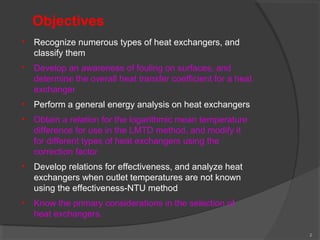
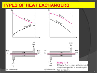
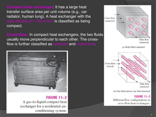
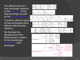
PRESENTATION BY 
PRABHAKAR YADAV
2 
Objectives 
• Recognize numerous types of heat exchangers, and 
classify them 
• Develop an awareness of fouling on surfaces, and 
determine the overall heat transfer coefficient for a heat 
exchanger 
• Perform a general energy analysis on heat exchangers 
• Obtain a relation for the logarithmic mean temperature 
difference for use in the LMTD method, and modify it 
for different types of heat exchangers using the 
correction factor 
• Develop relations for effectiveness, and analyze heat 
exchangers when outlet temperatures are not known 
using the effectiveness-NTU method 
• Know the primary considerations in the selection of 
heat exchangers.
3 
TYPES OF HEAT EXCHANGERS
4 
Compact heat exchanger: It has a large heat 
transfer surface area per unit volume (e.g., car 
radiator, human lung). A heat exchanger with the 
area density b > 700 m2/m3 is classified as being 
compact. 
Cross-flow: In compact heat exchangers, the two fluids 
usually move perpendicular to each other. The cross-flow 
is further classified as unmixed and mixed flow.
5 
Shell-and-tube heat exchanger: The most common type of heat 
exchanger in industrial applications. 
They contain a large number of tubes (sometimes several hundred) 
packed in a shell with their axes parallel to that of the shell. Heat 
transfer takes place as one fluid flows inside the tubes while the other 
fluid flows outside the tubes through the shell. 
Shell-and-tube heat exchangers are further classified according to the 
number of shell and tube passes involved.
6 
Regenerative heat exchanger: 
Involves the alternate passage of the 
hot and cold fluid streams through the 
same flow area. 
Dynamic-type regenerator: Involves a 
rotating drum and continuous flow of 
the hot and cold fluid through different 
portions of the drum so that any 
portion of the drum passes periodically 
through the hot stream, storing heat, 
and then through the cold stream, 
rejecting this stored heat. 
Condenser: One of the fluids is cooled 
and condenses as it flows through the 
heat exchanger. 
Boiler: One of the fluids absorbs heat 
and vaporizes.
7 
Plate and frame (or just plate) heat exchanger: Consists of a series of plates 
with corrugated flat flow passages. The hot and cold fluids flow in alternate 
passages, and thus each cold fluid stream is surrounded by two hot fluid streams, 
resulting in very effective heat transfer. Well suited for liquid-to-liquid applications. 
A plate-and-frame 
liquid-to-liquid heat 
exchanger.
8 
THE OVERALL HEAT TRANSFER COEFFICIENT 
• A heat exchanger typically involves two 
flowing fluids separated by a solid wall. 
• Heat is first transferred from the hot fluid to 
the wall by convection, through the wall by 
conduction, and from the wall to the cold 
fluid again by convection. 
• Any radiation effects are usually included in 
the convection heat transfer coefficients. 
Thermal resistance network 
associated with heat transfer in 
a double-pipe heat exchanger.
9 
U the overall heat transfer 
coefficient, W/m2×°C 
When 
The overall heat transfer coefficient U is dominated by the smaller convection 
coefficient. When one of the convection coefficients is much smaller than the other 
(say, hi << ho), we have 1/hi >> 1/ho, and thus U » hi. This situation arises frequently 
when one of the fluids is a gas and the other is a liquid. In such cases, fins are 
commonly used on the gas side to enhance the product UA and thus the heat 
transfer on that side.
10 
The overall heat transfer coefficient 
ranges from about 10 W/m2×°C for 
gas-to-gas heat exchangers to about 
10,000 W/m2×°C for heat exchangers 
that involve phase changes. 
When the tube is finned on one 
side to enhance heat transfer, the 
total heat transfer surface area on 
the finned side is 
For short fins of high 
thermal conductivity, we 
can use this total area in 
the convection 
resistance relation 
Rconv = 1/hAs 
To account for fin efficiency
Fouling Factor 
The performance of heat exchangers usually deteriorates with time as a result of 
accumulation of deposits on heat transfer surfaces. The layer of deposits represents 
additional resistance to heat transfer. This is represented by a fouling factor Rf. 
11 
The fouling factor increases with the operating temperature and the length of 
service and decreases with the velocity of the fluids.
12 
ANALYSIS OF HEAT EXCHANGERS 
An engineer often finds himself or herself in a position 
1. to select a heat exchanger that will achieve a specified temperature 
change in a fluid stream of known mass flow rate - the log mean 
temperature difference (or LMTD) method. 
2. to predict the outlet temperatures of the hot and cold fluid streams in 
a specified heat exchanger - the effectiveness–NTU method. 
The rate of heat transfer in heat 
exchanger (HE is insulated): 
heat capacity rate 
Two fluid 
streams that 
have the same 
capacity rates 
experience the 
same 
temperature 
change in a well-insulated 
heat 
exchanger.
Variation of 
fluid 
temperatures 
in a heat 
exchanger 
when one of 
the fluids 
condenses or 
boils. 
13 
is the rate of evaporation or condensation of the fluid 
hfg is the enthalpy of vaporization of the fluid at the specified temperature or pressure. 
The heat capacity rate of a fluid during a phase-change process must approach 
infinity since the temperature change is practically zero. 
DTm an appropriate mean (average) 
temperature difference between the two fluids
14 
THE LOG MEAN TEMPERATURE DIFFERENCE 
METHOD 
Variation of the fluid 
temperatures in a 
parallel-flow double-pipe 
heat exchanger. 
log mean 
temperature 
difference
15 
The LMTD method is very suitable for determining the size of a heat 
exchanger to realize prescribed outlet temperatures when the 
mass flow rates and the inlet and outlet temperatures of the hot 
and cold fluids are specified. 
With the LMTD method, the task is to select a heat exchanger that 
will meet the prescribed heat transfer requirements. The 
procedure to be followed by the selection process is: 
1. Select the type of heat exchanger suitable for the application. 
2. Determine any unknown inlet or outlet temperature and the heat 
transfer rate using an energy balance. 
3. Calculate the log mean temperature difference DTlm and the 
correction factor F, if necessary. 
4. Obtain (select or calculate) the value of the overall heat transfer 
coefficient U. 
5. Calculate the heat transfer surface area As . 
The task is completed by selecting a heat exchanger that has a heat 
transfer surface area equal to or larger than As.
16 
The arithmetic mean temperature difference 
The logarithmic mean temperature 
difference DTlm is an exact representation 
of the average temperature difference 
between the hot and cold fluids. 
Note that DTlm is always less than DTam. 
Therefore, using DTam in calculations 
instead of DTlm will overestimate the rate of 
heat transfer in a heat exchanger between 
the two fluids. 
When DT1 differs from DT2 by no more than 
40 percent, the error in using the arithmetic 
mean temperature difference is less than 1 
percent. But the error increases to 
undesirable levels when DT1 differs from 
DT2 by greater amounts.
Counter-Flow Heat Exchangers 
In the limiting case, the cold fluid will be 
heated to the inlet temperature of the hot 
fluid. 
However, the outlet temperature of the cold 
fluid can never exceed the inlet 
temperature of the hot fluid. 
For specified inlet and outlet temperatures, 
DTlm a counter-flow heat exchanger is 
always greater than that for a parallel-flow 
heat exchanger. 
That is, DTlm, CF > DTlm, PF, and thus a 
smaller surface area (and thus a smaller 
heat exchanger) is needed to achieve a 
specified heat transfer rate in a counter-flow 
17 
heat exchanger. 
When the heat capacity rates 
of the two fluids are equal
18 
Applications of Heat Exchangers 
Heat Exchangers 
prevent car engine 
overheating and 
increase efficiency 
Heat 
exchangers are 
used in AC and 
furnaces
19 
THE EFFECTIVENESS–NTU METHOD 
A second kind of problem encountered in heat exchanger analysis is the 
determination of the heat transfer rate and the outlet temperatures of the hot and 
cold fluids for prescribed fluid mass flow rates and inlet temperatures when the type 
and size of the heat exchanger are specified. 
Heat transfer effectiveness 
the maximum possible heat transfer rate 
Cmin is the smaller of Ch and Cc
20 
Actual heat transfer rate
21 
The effectiveness of a 
heat exchanger depends 
on the geometry of the 
heat exchanger as well 
as the flow arrangement. 
Therefore, different types 
of heat exchangers have 
different effectiveness 
relations. 
We illustrate the 
development of the 
effectiveness e relation 
for the double-pipe 
parallel-flow heat 
exchanger.
22 
Effectiveness relations of the heat exchangers typically involve the 
dimensionless group UAs /Cmin. 
This quantity is called the number of transfer units NTU. 
For specified values of U and Cmin, the value 
of NTU is a measure of the surface area As. 
Thus, the larger the NTU, the larger the heat 
capacity exchanger. 
ratio 
The effectiveness of a heat exchanger is a function of the 
number of transfer units NTU and the capacity ratio c.
23 
Observations from the effectiveness relations and charts 
• The value of the effectiveness ranges from 0 to 1. It increases 
rapidly with NTU for small values (up to about NTU = 1.5) but 
rather slowly for larger values. Therefore, the use of a heat 
exchanger with a large NTU (usually larger than 3) and thus a 
large size cannot be justified economically, since a large 
increase in NTU in this case corresponds to a small increase in 
effectiveness. 
• For a given NTU and capacity ratio c = Cmin /Cmax, the counter-flow 
heat exchanger has the highest effectiveness, followed 
closely by the cross-flow heat exchangers with both fluids 
unmixed. The lowest effectiveness values are encountered in 
parallel-flow heat exchangers. 
• The effectiveness of a heat exchanger is independent of the 
capacity ratio c for NTU values of less than about 0.3. 
• The value of the capacity ratio c ranges between 0 and 1. For a 
given NTU, the effectiveness becomes a maximum for c = 0 
(e.g., boiler, condenser) and a minimum for c = 1 (when the heat 
capacity rates of the two fluids are equal).
24 
SELECTION OF HEAT EXCHANGERS 
The uncertainty in the predicted value of U can exceed 30 percent. Thus, it is 
natural to tend to overdesign the heat exchangers. 
Heat transfer enhancement in heat exchangers is usually accompanied by 
increased pressure drop, and thus higher pumping power. 
Therefore, any gain from the enhancement in heat transfer should be weighed 
against the cost of the accompanying pressure drop. 
Usually, the more viscous fluid is more suitable for the shell side (larger 
passage area and thus lower pressure drop) and the fluid with the higher 
pressure for the tube side. 
The proper selection of 
a heat exchanger depends 
on several factors: 
• Heat Transfer Rate 
• Cost 
• Pumping Power 
• Size and Weight 
• Type 
• Materials 
The rate of heat transfer in the 
prospective heat exchanger 
The annual cost of electricity associated with 
the operation of the pumps and fans
Summary 
 Types of Heat Exchangers 
 The Overall Heat Transfer Coefficient 
Fouling factor 
 Analysis of Heat Exchangers 
 The Log Mean Temperature Difference 
Method 
Counter-Flow Heat Exchangers 
Multipass and Cross-Flow Heat Exchangers: 
Use of a Correction Factor 
 The Effectiveness–NTU Method 
 Selection of Heat Exchangers 
25

Heat exchangers

  • 1.
  • 2.
    2 Objectives •Recognize numerous types of heat exchangers, and classify them • Develop an awareness of fouling on surfaces, and determine the overall heat transfer coefficient for a heat exchanger • Perform a general energy analysis on heat exchangers • Obtain a relation for the logarithmic mean temperature difference for use in the LMTD method, and modify it for different types of heat exchangers using the correction factor • Develop relations for effectiveness, and analyze heat exchangers when outlet temperatures are not known using the effectiveness-NTU method • Know the primary considerations in the selection of heat exchangers.
  • 3.
    3 TYPES OFHEAT EXCHANGERS
  • 4.
    4 Compact heatexchanger: It has a large heat transfer surface area per unit volume (e.g., car radiator, human lung). A heat exchanger with the area density b > 700 m2/m3 is classified as being compact. Cross-flow: In compact heat exchangers, the two fluids usually move perpendicular to each other. The cross-flow is further classified as unmixed and mixed flow.
  • 5.
    5 Shell-and-tube heatexchanger: The most common type of heat exchanger in industrial applications. They contain a large number of tubes (sometimes several hundred) packed in a shell with their axes parallel to that of the shell. Heat transfer takes place as one fluid flows inside the tubes while the other fluid flows outside the tubes through the shell. Shell-and-tube heat exchangers are further classified according to the number of shell and tube passes involved.
  • 6.
    6 Regenerative heatexchanger: Involves the alternate passage of the hot and cold fluid streams through the same flow area. Dynamic-type regenerator: Involves a rotating drum and continuous flow of the hot and cold fluid through different portions of the drum so that any portion of the drum passes periodically through the hot stream, storing heat, and then through the cold stream, rejecting this stored heat. Condenser: One of the fluids is cooled and condenses as it flows through the heat exchanger. Boiler: One of the fluids absorbs heat and vaporizes.
  • 7.
    7 Plate andframe (or just plate) heat exchanger: Consists of a series of plates with corrugated flat flow passages. The hot and cold fluids flow in alternate passages, and thus each cold fluid stream is surrounded by two hot fluid streams, resulting in very effective heat transfer. Well suited for liquid-to-liquid applications. A plate-and-frame liquid-to-liquid heat exchanger.
  • 8.
    8 THE OVERALLHEAT TRANSFER COEFFICIENT • A heat exchanger typically involves two flowing fluids separated by a solid wall. • Heat is first transferred from the hot fluid to the wall by convection, through the wall by conduction, and from the wall to the cold fluid again by convection. • Any radiation effects are usually included in the convection heat transfer coefficients. Thermal resistance network associated with heat transfer in a double-pipe heat exchanger.
  • 9.
    9 U theoverall heat transfer coefficient, W/m2×°C When The overall heat transfer coefficient U is dominated by the smaller convection coefficient. When one of the convection coefficients is much smaller than the other (say, hi << ho), we have 1/hi >> 1/ho, and thus U » hi. This situation arises frequently when one of the fluids is a gas and the other is a liquid. In such cases, fins are commonly used on the gas side to enhance the product UA and thus the heat transfer on that side.
  • 10.
    10 The overallheat transfer coefficient ranges from about 10 W/m2×°C for gas-to-gas heat exchangers to about 10,000 W/m2×°C for heat exchangers that involve phase changes. When the tube is finned on one side to enhance heat transfer, the total heat transfer surface area on the finned side is For short fins of high thermal conductivity, we can use this total area in the convection resistance relation Rconv = 1/hAs To account for fin efficiency
  • 11.
    Fouling Factor Theperformance of heat exchangers usually deteriorates with time as a result of accumulation of deposits on heat transfer surfaces. The layer of deposits represents additional resistance to heat transfer. This is represented by a fouling factor Rf. 11 The fouling factor increases with the operating temperature and the length of service and decreases with the velocity of the fluids.
  • 12.
    12 ANALYSIS OFHEAT EXCHANGERS An engineer often finds himself or herself in a position 1. to select a heat exchanger that will achieve a specified temperature change in a fluid stream of known mass flow rate - the log mean temperature difference (or LMTD) method. 2. to predict the outlet temperatures of the hot and cold fluid streams in a specified heat exchanger - the effectiveness–NTU method. The rate of heat transfer in heat exchanger (HE is insulated): heat capacity rate Two fluid streams that have the same capacity rates experience the same temperature change in a well-insulated heat exchanger.
  • 13.
    Variation of fluid temperatures in a heat exchanger when one of the fluids condenses or boils. 13 is the rate of evaporation or condensation of the fluid hfg is the enthalpy of vaporization of the fluid at the specified temperature or pressure. The heat capacity rate of a fluid during a phase-change process must approach infinity since the temperature change is practically zero. DTm an appropriate mean (average) temperature difference between the two fluids
  • 14.
    14 THE LOGMEAN TEMPERATURE DIFFERENCE METHOD Variation of the fluid temperatures in a parallel-flow double-pipe heat exchanger. log mean temperature difference
  • 15.
    15 The LMTDmethod is very suitable for determining the size of a heat exchanger to realize prescribed outlet temperatures when the mass flow rates and the inlet and outlet temperatures of the hot and cold fluids are specified. With the LMTD method, the task is to select a heat exchanger that will meet the prescribed heat transfer requirements. The procedure to be followed by the selection process is: 1. Select the type of heat exchanger suitable for the application. 2. Determine any unknown inlet or outlet temperature and the heat transfer rate using an energy balance. 3. Calculate the log mean temperature difference DTlm and the correction factor F, if necessary. 4. Obtain (select or calculate) the value of the overall heat transfer coefficient U. 5. Calculate the heat transfer surface area As . The task is completed by selecting a heat exchanger that has a heat transfer surface area equal to or larger than As.
  • 16.
    16 The arithmeticmean temperature difference The logarithmic mean temperature difference DTlm is an exact representation of the average temperature difference between the hot and cold fluids. Note that DTlm is always less than DTam. Therefore, using DTam in calculations instead of DTlm will overestimate the rate of heat transfer in a heat exchanger between the two fluids. When DT1 differs from DT2 by no more than 40 percent, the error in using the arithmetic mean temperature difference is less than 1 percent. But the error increases to undesirable levels when DT1 differs from DT2 by greater amounts.
  • 17.
    Counter-Flow Heat Exchangers In the limiting case, the cold fluid will be heated to the inlet temperature of the hot fluid. However, the outlet temperature of the cold fluid can never exceed the inlet temperature of the hot fluid. For specified inlet and outlet temperatures, DTlm a counter-flow heat exchanger is always greater than that for a parallel-flow heat exchanger. That is, DTlm, CF > DTlm, PF, and thus a smaller surface area (and thus a smaller heat exchanger) is needed to achieve a specified heat transfer rate in a counter-flow 17 heat exchanger. When the heat capacity rates of the two fluids are equal
  • 18.
    18 Applications ofHeat Exchangers Heat Exchangers prevent car engine overheating and increase efficiency Heat exchangers are used in AC and furnaces
  • 19.
    19 THE EFFECTIVENESS–NTUMETHOD A second kind of problem encountered in heat exchanger analysis is the determination of the heat transfer rate and the outlet temperatures of the hot and cold fluids for prescribed fluid mass flow rates and inlet temperatures when the type and size of the heat exchanger are specified. Heat transfer effectiveness the maximum possible heat transfer rate Cmin is the smaller of Ch and Cc
  • 20.
    20 Actual heattransfer rate
  • 21.
    21 The effectivenessof a heat exchanger depends on the geometry of the heat exchanger as well as the flow arrangement. Therefore, different types of heat exchangers have different effectiveness relations. We illustrate the development of the effectiveness e relation for the double-pipe parallel-flow heat exchanger.
  • 22.
    22 Effectiveness relationsof the heat exchangers typically involve the dimensionless group UAs /Cmin. This quantity is called the number of transfer units NTU. For specified values of U and Cmin, the value of NTU is a measure of the surface area As. Thus, the larger the NTU, the larger the heat capacity exchanger. ratio The effectiveness of a heat exchanger is a function of the number of transfer units NTU and the capacity ratio c.
  • 23.
    23 Observations fromthe effectiveness relations and charts • The value of the effectiveness ranges from 0 to 1. It increases rapidly with NTU for small values (up to about NTU = 1.5) but rather slowly for larger values. Therefore, the use of a heat exchanger with a large NTU (usually larger than 3) and thus a large size cannot be justified economically, since a large increase in NTU in this case corresponds to a small increase in effectiveness. • For a given NTU and capacity ratio c = Cmin /Cmax, the counter-flow heat exchanger has the highest effectiveness, followed closely by the cross-flow heat exchangers with both fluids unmixed. The lowest effectiveness values are encountered in parallel-flow heat exchangers. • The effectiveness of a heat exchanger is independent of the capacity ratio c for NTU values of less than about 0.3. • The value of the capacity ratio c ranges between 0 and 1. For a given NTU, the effectiveness becomes a maximum for c = 0 (e.g., boiler, condenser) and a minimum for c = 1 (when the heat capacity rates of the two fluids are equal).
  • 24.
    24 SELECTION OFHEAT EXCHANGERS The uncertainty in the predicted value of U can exceed 30 percent. Thus, it is natural to tend to overdesign the heat exchangers. Heat transfer enhancement in heat exchangers is usually accompanied by increased pressure drop, and thus higher pumping power. Therefore, any gain from the enhancement in heat transfer should be weighed against the cost of the accompanying pressure drop. Usually, the more viscous fluid is more suitable for the shell side (larger passage area and thus lower pressure drop) and the fluid with the higher pressure for the tube side. The proper selection of a heat exchanger depends on several factors: • Heat Transfer Rate • Cost • Pumping Power • Size and Weight • Type • Materials The rate of heat transfer in the prospective heat exchanger The annual cost of electricity associated with the operation of the pumps and fans
  • 25.
    Summary  Typesof Heat Exchangers  The Overall Heat Transfer Coefficient Fouling factor  Analysis of Heat Exchangers  The Log Mean Temperature Difference Method Counter-Flow Heat Exchangers Multipass and Cross-Flow Heat Exchangers: Use of a Correction Factor  The Effectiveness–NTU Method  Selection of Heat Exchangers 25