
Recommended
More Related Content
What's hot
Similar to Designing mobile applications for HDMI
Similar to Designing mobile applications for HDMI (20)
Designing mobile applications for HDMI
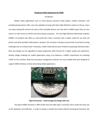
- 1. Designing mobile applications for HDMI Ian Beavers Mobile media applications such as smart phones, personal media players, mobile computers, and portable gaming devices offer users the capability to bring with them High Definition content on the go. Users can enjoy viewing HD content not only on their portable devices, but now with an HDMI output they can also watch it in their homes on HDTVs and home theater projectors. The new High Definition Multimedia Interface (HDMI) 1.4 standard now offers an ultra-small form factor connector that is better suited for use with cell phones and other portable media devices. However, the connector introduces new printed circuit board routing challenges due its small pin pitch. Previously, mobile media devices were limited to outputting interlaced video. Now new designs can be upgraded to output progressive video formats for a higher quality user experience. Another design challenge for mobile applications using Li-ion batteries is HDMI’s requirement for providing +5VDC on this interface. New low-cost power management solutions are now available that were designed to support HDMI interfaces in these demanding mobile applications. Type D Connector – Small enough, but design with care The type D HDMI connector is 40% smaller than the older type C connector and is nearly the same size as the ubiquitous mini-USB port. In order to achieve a smaller form factor without removing pin functions, the
- 2. type D uses 0.4mm pitch pin spacing instead of the 0.5mm pitch seen on the large type A connector. While the 0.4mm pitch is the same as the type C, a staggered dual row format is used on type D due to its compact size. This creates an effective pitch of 0.2mm between both rows of pins. The four transition minimized differential signaling (TMDS) pairs are split between two on the front row and two on the back row. Unless the system designer uses very aggressive board layout rules to route all the signal pairs on one layer, it is recommended to route two TMDS pairs on a different board layer. This is a departure from the ability to route all of the signals on one layer for type A and type C connectors. When using a type D connector, careful attention also needs to be given to the impedance matching through these TMDS vias and trace lengths that are routed to another board layer and back. Generally, the differential trace impedance within the TMDS pair should be 100 ohms with a 15 ohm tolerance. Since there is no formal compliance test for the impedance matching on the HDMI transmitter side, the 100 ohm target within a pair may be overlooked. However, an abrupt mismatch on one channel can cause reflections on the line that result in bit errors to the HDMI receiver. These issues may actually mask themselves at some particular video frequencies, while showing problems at others. Figure 1 shows the impact of an improperly designed HDMI transmit impedance using a 480p video pattern as seen at the receiver input. In this case, the reflection does not occur in the sensitive center of the eye where the decision point is made in the receiver. The HDMI video signal is actually received without error. Using a faster 720p pattern through the same traces in Figure 2, it can be seen that the fixed time reflection is in the center of the eye where the receiver now takes on bit errors that are manifested as “frame flashing” on the display. Careful attention to maintaining proper via impedance control within the layout and use of Time Domain Reflectometry (TDR) verification can help prevent impedance mismatch issues in an HDMI system.
- 3. Figure 1 – Impedance mismatch using 480p video format Figure 2 – Impedance mismatch using 720p video format 1080p output for full HD displays For most mobile video applications, the consumer will probably spend a vast majority of the operation time generating and using content on the device itself. While low active power is important, the HDMI transmit and support devices must have minimal standby current consumption to preserve precious battery life when not in use. A cost efficient solution removes the need for supply switching.
- 4. HDMI requires a 480p video format to be offered as one output option by all source connections. If the system designer is upgrading a legacy composite video processing core in the mobile system, it will provide the 480 interlaced output but not the 480 progressive video requirements by the HDMI standard. Thus, the mobile HDMI system developer may need a way to make the transition to progressive video with a de-interlacing method. A smart motion adaptive de-interlacing algorithm with no external memory, such as that used in the ADV7541, can help remove undesirable video artifacts exhibited in interlaced video. Some applications have already moved to a high definition output by scaling the video to 1080 lines interlaced. Most existing mobile video processors are limited to 1080i display resolution output. But offering a true 1080 progressive interface creates a value-added feature to the marketplace that cannot easily be done without a costly upgrade of the mobile video processor or embedded application specific integrated circuit (ASIC). This issue can be solved by using an HDMI transmitter solution such as the ADV7541 which offers a motion adaptive 1080 interlaced to progressive conversion. This will allow true 1080p output on the HDMI interface while using an existing mobile video processor. Solving the HDMI +5V design dilemma Yet another HDMI challenge in the mobile and handset space is the requirement of the +5V/55mA output and internal +3.3V pull-up for serial communications over the link. The HDMI transmit system is required to provide +5V with 55mA compliance to support downstream extended display identification data (EDID) memory and Hot Plug feedback. Mobile system power domain consolidation down to 1.8V and 1.2V when using Li-ion batteries limits the number of options for the +5V output and often requires a solution to directly use the battery (VBAT) domain. A typical VBAT domain may deplete down to 2.5V over the life of a charge. Fixed regulators can be inefficient without a switch to disable the output during the time when HDMI is not used. The solution must also be flexible enough to accommodate both the VBAT system noise and voltage droop. Embedded short
- 5. circuit protection features in the regulator are not only smart for the mobile system, but also have a requirement in the HDMI specification. A boost regulator optimized for mobile HDMI applications, such as AD9394, offers these features and is able to supply both +5V and +3.3V DC sources only during HDMI operation without compromising the ultra-low power system needs of the design. Designed specifically for mobile HDMI applications, the single wire control AD9394 boost regulator offers both +5V and +3.3V output in a small 2.0 x 1.5 x 0.6mm form factor WLCSP to meet HDMI compliance specifications over a VBAT input range 4.5 - 2.5V. The AD9394 offers a short circuit protection feature to prevent damage to the system and battery. AD9394 has standby power consumption <1uW and active unloaded consumption of 5uW. The 150MHz ADV7541 HDMI transmitter offers a complete solution for 1080p video and audio transmission on mobile devices. It’s interlaced to progressive video conversion for both 480 and 1080 video formats offers designers the solution to bridge the gap to high definition output. The ADV7541 comes in a 3.75 x 3.75mm x 0.6mm form factor WLCSP with minimal software overhead. The AD9394 was designed to operate with the ADV7541 to provide low cost, small size solutions for mobile devices using an HDMI output. +5V OUT VBAT (4.5-2.5V) AD9394 +3.3V OUT EN 1.8V I2C CEC Graphics Audio DDC 1080p Video to TV ASIC ADV7541 TMDS 1080i Video 8 HDMI Type D 16 Figure 3 – Example of mobile media system design with HDMI output
- 6. In summary, the new ultra small form factor type D connector introduced in the HDMI 1.4 specification requires special care in PCB routing of impedance matched TMDS signals using vias. Mobile media systems transitioning to enable HDMI output can achieve full high definition 1080p when using existing mobile video processors with only an interlaced output. The HDMI +5V compliance requirement using a decaying VBAT as a supply can now be solved with a boost regulator designed for HDMI applications.