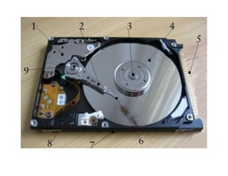
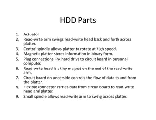
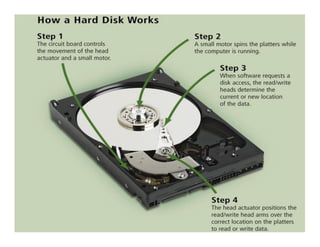
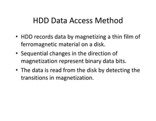
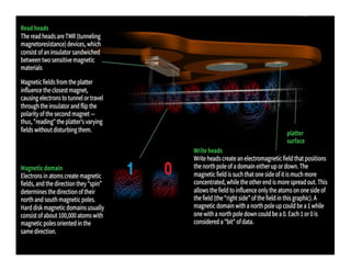
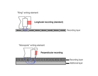
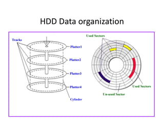
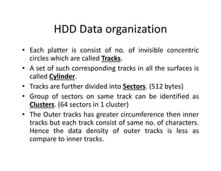
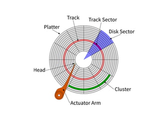
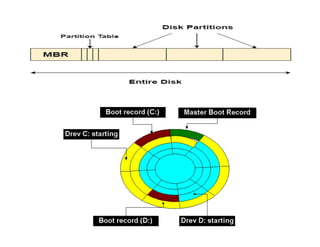
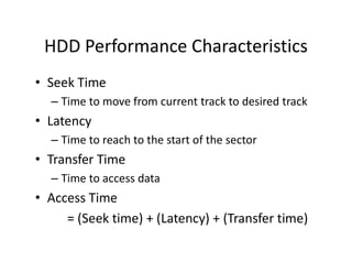
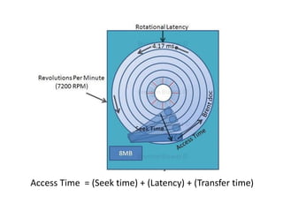
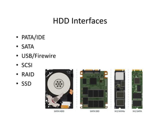
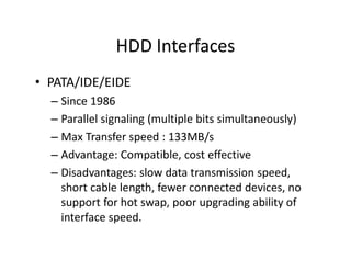
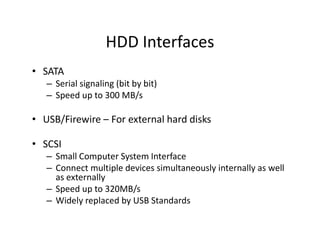
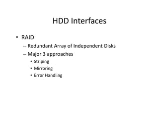
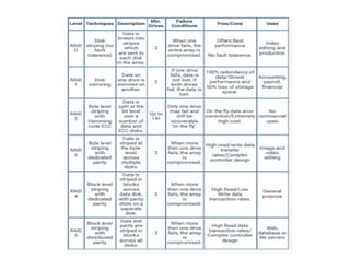
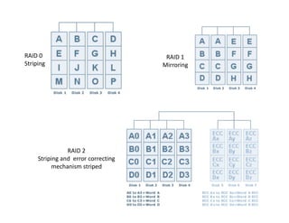
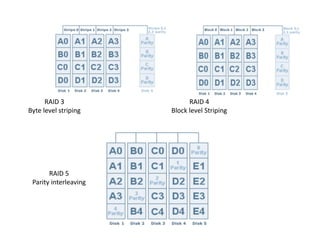
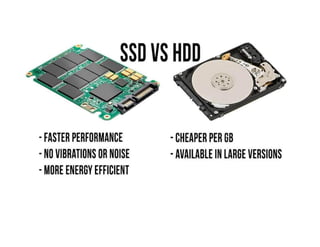
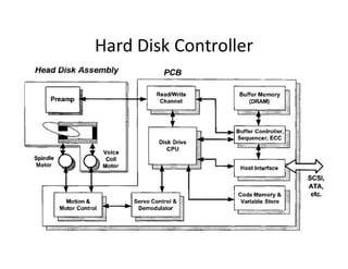
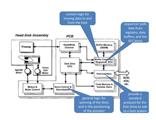
Hard Disk Drives
HDD Parts
1. Actuator
2. Read-write arm swings read-write head back and forth across
platter.
3. Central spindle allows platter to rotate at high speed.
4. Magnetic platter stores information in binary form.
5. Plug connections link hard drive to circuit board in personal
computer.
6. Read-write head is a tiny magnet on the end of the read-write
arm.
7. Circuit board on underside controls the flow of data to and from
the platter.
8. Flexible connector carries data from circuit board to read-write
head and platter.
9. Small spindle allows read-write arm to swing across platter.
IBM’s DASD
HDD Data Access Method
• HDD records data by magnetizing a thin film of
ferromagnetic material on a disk.
• Sequential changes in the direction of
magnetization represent binary data bits.
• The data is read from the disk by detecting the
transitions in magnetization.
HDD Data organization
• Each platter is consist of no. of invisible concentric
circles which are called Tracks.
• A set of such corresponding tracks in all the surfaces is
called Cylinder.
• Tracks are further divided into Sectors. (512 bytes)
• Group of sectors on same track can be identified as
Clusters. (64 sectors in 1 cluster)
• The Outer tracks has greater circumference then inner
tracks but each track consist of same no. of characters.
Hence the data density of outer tracks is less as
compare to inner tracks.
Zone Bit Recording
HDD Performance Characteristics
• Seek Time
– Time to move from current track to desired track
• Latency
– Time to reach to the start of the sector
• Transfer Time
– Time to access data
• Access Time
= (Seek time) + (Latency) + (Transfer time)
Access Time = (Seek time) + (Latency) + (Transfer time)
HDD Interfaces
• PATA/IDE
• SATA
• USB/Firewire
• SCSI
• RAID
• SSD
HDD Interfaces
• PATA/IDE/EIDE
– Since 1986
– Parallel signaling (multiple bits simultaneously)
– Max Transfer speed : 133MB/s
– Advantage: Compatible, cost effective
– Disadvantages: slow data transmission speed,
short cable length, fewer connected devices, no
support for hot swap, poor upgrading ability of
interface speed.
HDD Interfaces
• SATA
– Serial signaling (bit by bit)
– Speed up to 300 MB/s
• USB/Firewire – For external hard disks
• SCSI
– Small Computer System Interface
– Connect multiple devices simultaneously internally as well
as externally
– Speed up to 320MB/s
– Widely replaced by USB Standards
HDD Interfaces
• RAID
– Redundant Array of Independent Disks
– Major 3 approaches
• Striping
• Mirroring
• Error Handling
RAID 0
Striping
RAID 1
Mirroring
RAID 2
Striping and error correcting
mechanism striped
RAID 3
Byte level striping
RAID 4
Block level Striping
RAID 5
Parity interleaving
Hard Disk Controller
provide a
standard
protocol for the
Disk Drive to talk
to a host system
contain logic for
moving data to and
from the host sequencer pulls
data from
registers, data
buffers, and the
ECC block
general logic for
spinning of the discs
and in the positioning
of the actuator

HDD.pdf

  • 1.
  • 3.
    HDD Parts 1. Actuator 2.Read-write arm swings read-write head back and forth across platter. 3. Central spindle allows platter to rotate at high speed. 4. Magnetic platter stores information in binary form. 5. Plug connections link hard drive to circuit board in personal computer. 6. Read-write head is a tiny magnet on the end of the read-write arm. 7. Circuit board on underside controls the flow of data to and from the platter. 8. Flexible connector carries data from circuit board to read-write head and platter. 9. Small spindle allows read-write arm to swing across platter.
  • 4.
  • 6.
    HDD Data AccessMethod • HDD records data by magnetizing a thin film of ferromagnetic material on a disk. • Sequential changes in the direction of magnetization represent binary data bits. • The data is read from the disk by detecting the transitions in magnetization.
  • 9.
  • 10.
    HDD Data organization •Each platter is consist of no. of invisible concentric circles which are called Tracks. • A set of such corresponding tracks in all the surfaces is called Cylinder. • Tracks are further divided into Sectors. (512 bytes) • Group of sectors on same track can be identified as Clusters. (64 sectors in 1 cluster) • The Outer tracks has greater circumference then inner tracks but each track consist of same no. of characters. Hence the data density of outer tracks is less as compare to inner tracks.
  • 12.
  • 15.
    HDD Performance Characteristics •Seek Time – Time to move from current track to desired track • Latency – Time to reach to the start of the sector • Transfer Time – Time to access data • Access Time = (Seek time) + (Latency) + (Transfer time)
  • 16.
    Access Time =(Seek time) + (Latency) + (Transfer time)
  • 17.
    HDD Interfaces • PATA/IDE •SATA • USB/Firewire • SCSI • RAID • SSD
  • 18.
    HDD Interfaces • PATA/IDE/EIDE –Since 1986 – Parallel signaling (multiple bits simultaneously) – Max Transfer speed : 133MB/s – Advantage: Compatible, cost effective – Disadvantages: slow data transmission speed, short cable length, fewer connected devices, no support for hot swap, poor upgrading ability of interface speed.
  • 19.
    HDD Interfaces • SATA –Serial signaling (bit by bit) – Speed up to 300 MB/s • USB/Firewire – For external hard disks • SCSI – Small Computer System Interface – Connect multiple devices simultaneously internally as well as externally – Speed up to 320MB/s – Widely replaced by USB Standards
  • 20.
    HDD Interfaces • RAID –Redundant Array of Independent Disks – Major 3 approaches • Striping • Mirroring • Error Handling
  • 22.
    RAID 0 Striping RAID 1 Mirroring RAID2 Striping and error correcting mechanism striped
  • 23.
    RAID 3 Byte levelstriping RAID 4 Block level Striping RAID 5 Parity interleaving
  • 25.
  • 26.
    provide a standard protocol forthe Disk Drive to talk to a host system contain logic for moving data to and from the host sequencer pulls data from registers, data buffers, and the ECC block general logic for spinning of the discs and in the positioning of the actuator