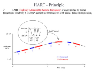
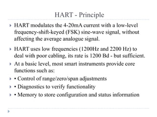
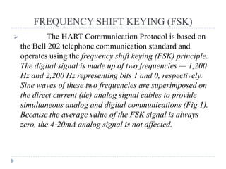
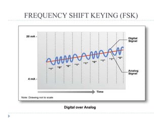
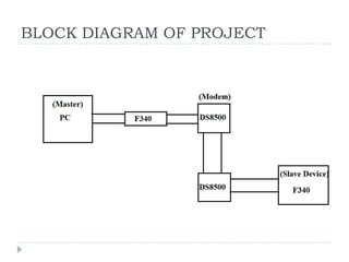
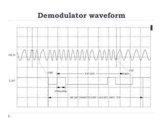
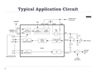
HART (Highway Addressable Remote Transducer) was developed to add digital communication capabilities to existing 4-20mA analog loops. It uses frequency-shift-keying to modulate two frequencies onto the analog signal without affecting the average current. The HART protocol allows simultaneous analog and digital multi-drop communication for monitoring and configuration of smart field devices. A C8051F340 microcontroller and HART modem chip like the DS8500 can be used to implement the physical and data link layers of the HART protocol for communication with field transmitters.


![[Advantech] Modbus protocol training (ModbusTCP, ModbusRTU)](https://cdn.slidesharecdn.com/ss_thumbnails/modbustraining-161115125830-thumbnail.jpg?width=640&height=640&fit=bounds)