The document provides an overview of HART communication, including how it originated, its theory of operation, benefits, and conclusions. Some key points:
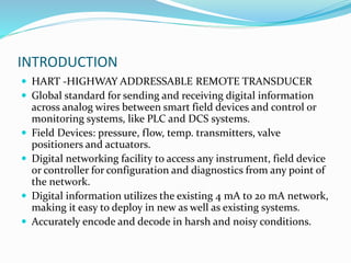
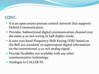
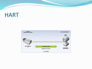
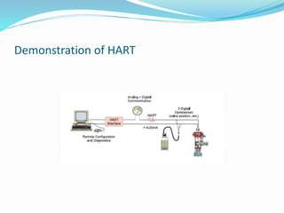
- HART allows digital communication over analog 4-20mA wiring, providing additional process data without disrupting existing infrastructure.
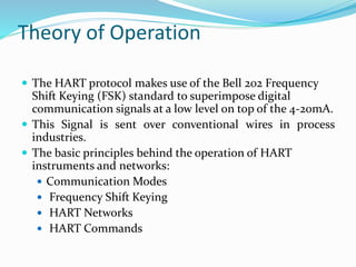
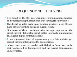
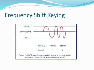
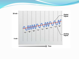
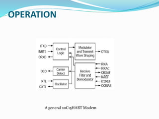
- It uses Frequency Shift Keying to encode digital signals which are superimposed on the analog current loop.
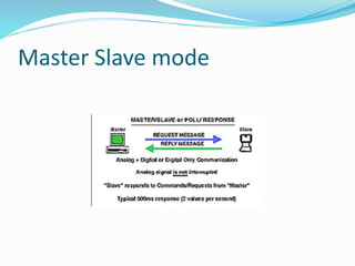
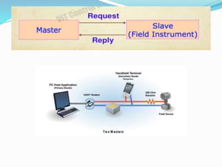
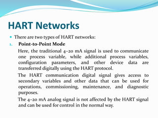
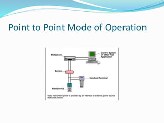
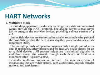
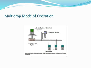
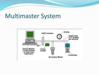
- HART provides bidirectional communication, device configuration/diagnostics, and supports point-to-point and multidrop network topologies.
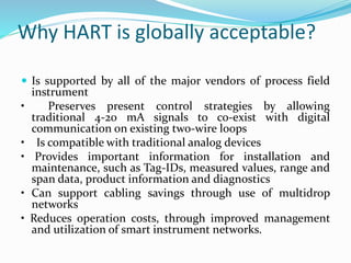
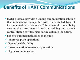
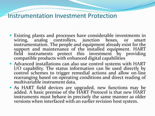
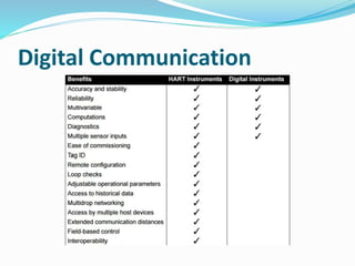
- Benefits include improved operations, flexibility, and protection of existing instrumentation investments.


![References
[1]. Introduction to HART
[Online]. Available FTP: http://en.hartcomm.org/
[2].http://www2.emersonprocess.com/siteadmincenter/P
M%20Central%20Web%20Documents/Eng%20Sch%20-
%20Buses%20201.pdf
3. INSTRUMENTATION TOOL
http://instrumentationtools.com
4.http://een.iust.ac.ir/profs/Shahri/Computer%20Buses_8
4/HART_new%20Doc.htm](https://image.slidesharecdn.com/amithartpresentation-170828112217/85/Amit-hart-presentation-43-320.jpg)