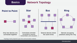
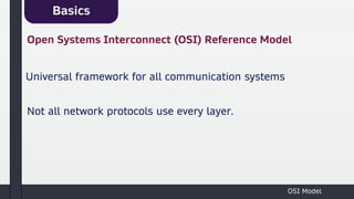
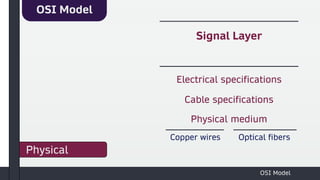
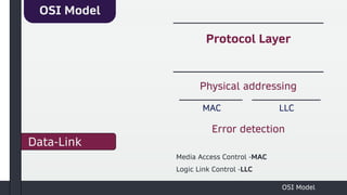
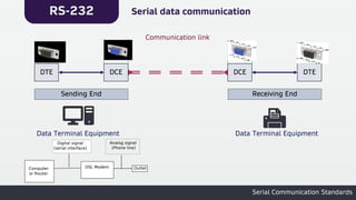
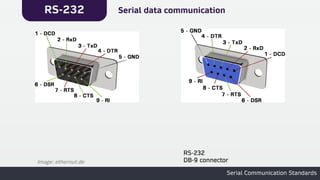
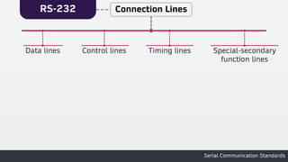
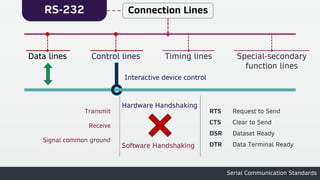
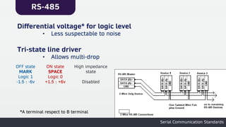
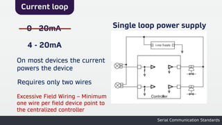
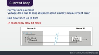
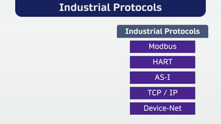
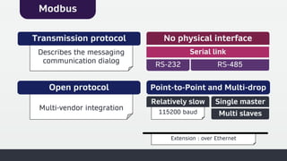
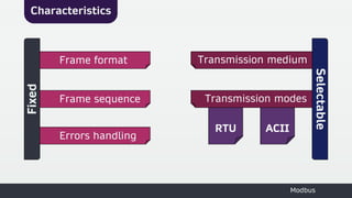
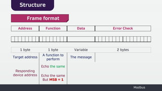
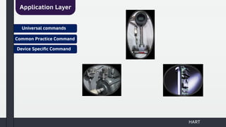
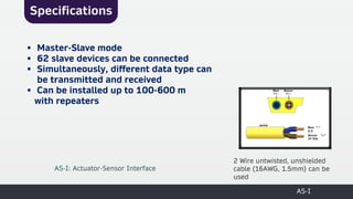
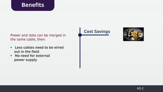
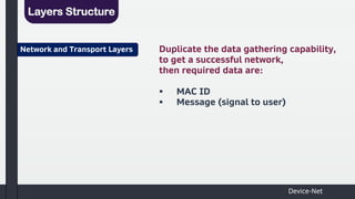
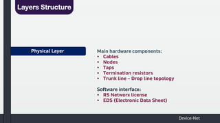
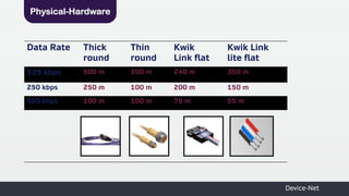
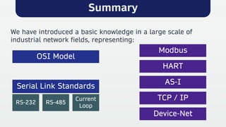
4. Basics
Introduction
Network Topology
Point to Point Star Bus Ring
Only two devices are
connected together
Centralized controller
connected to several
transmitters and actuators
Several devices share
the same wires
Devices occupying
positions along the ring
Topology mainly depends upon the communication method
6. Basics
OSI Model
Open Systems Interconnect (OSI) Reference Model
Universal framework for all communication systems
Not all network protocols use every layer.
22. RS-232
Serial Communication Standards
Connection Lines
Data lines Control lines
Transfer data
Driver
Receiver
-5v → -25v
-3v → -25v
+5v → +25v
+3v → +25v
Undefined Logic
* Logic level referenced to ground
23. RS-232
Serial Communication Standards
Connection Lines
Data lines Control lines
Interactive device control
Hardware Handshaking
RTS
CTS
DSR
DTR
Request to Send
Clear to Send
Dataset Ready
Data Terminal Ready
Transmit
Receive
Signal common ground
Software Handshaking
25. RS-485
Serial Communication Standards
Extension of RS-422
• Multi-drop on 2 wires
• Distance up to 1200m **
• Data rates up to 10Mbps **
Supports multiple modules
• Up to 32 driver/receiver on the same line
• Repeater adds more modules
** Maximum bit rate and maximum length cannot be achieved at the same time
26. RS-485
Serial Communication Standards
Differential voltage* for logic level
• Less suspectable to noise
Tri-state line driver
• Allows multi-drop
OFF state
MARK
Logic 1
-1.5 : -6v
ON state
SPACE
Logic 0
+1.5 : +6v
High impedance
state
Disabled
*A terminal respect to B terminal
27. Current loop
Serial Communication Standards
0 - 20mA
4 - 20mA
Single loop power supply
On most devices the current
powers the device
Requires only two wires
Excessive Field Wiring – Minimum
one wire per field device point to
the centralized controller
28. Current loop
Serial Communication Standards
Current measurement
Voltage drop due to long distances don’t employ measurement error
In reasonably slow bit rates
Can drive lines up to 1km
32. Extension : over Ethernet
Extension : over Ethernet
115200 baud
115200 baud
Multi-vendor integration
RS-232 RS-485
RS-232
RS-232 RS-485
RS-485
Serial link
Serial link
No physical interface
Describes the messaging
communication dialog
Describes the messaging
communication dialog
Transmission protocol
Modbus
Open protocol
Open protocol Point-to-Point and Multi-drop
Point-to-Point and Multi-drop
Relatively slow
Relatively slow Single master
Single master
Multi slaves
Multi slaves
35. Structure
Modbus
Address Function Data Error Check
1 byte 1 byte Variable 2 bytes
Target address
A function to
perform
The message
Responding
device address
Echo the same
Echo the same
But MSB = 1
Frame format
36. Structure
Modbus
Address Function Data Error Check
1 byte 1 byte Variable 2 bytes
Target address
A function to
perform
The message
Responding
device address
Echo the same
Echo the same
But MSB = 1
Frame format
39. Challenge
Analog Signal
The Knowhow of data transfer for two different types:
Digital Signal
With no interference
HART: Highway Addressable Remote Transducer
40. Frequency Shift Keying
In 1990s,
FSK (Frequency Shift Modulation) technique has been certified
Σ
4mA
20mA
42. HART
▪ Power Supply
▪ Field Device
▪ Host
Point to Point
Smart sensor with an output current signal in range of 4-20mA
Primary controller can be sufficient, such as PLC
or DCS, and a handheld can be a secondary controller
Hardware Implementation
HART Network
43. HART
The FSK technique must be
used for digital data
sharing such as the ID
related to each field device
Cat 5 shielded, twisted
pair wire is
recommended
Multi-drop HART Network
45. HART
Smart devices Host
▪ No message request
needed
▪ High data transfer rate
(3-4 data per second)
▪ Can be integrated with
point to point network
Burst Mode Communication
Mode
47. HART
Preamble
▪ First field in sent message
▪ Wake up and synchronize
all connected receivers in
the network
Data Link Layer
48. HART
Delimiter ▪ Single byte field
▪ Indication to the end of preamble field
▪ Considered to be the Start field
▪ Classifies the message type to a
:
Request from
Master
Response of Slave
Data Link Layer
49. HART
Address Specifies the destination address and its type
Data Link Layer
Polling
Address
Single byte Five bytes
ID Address
50. HART
Command ▪ Single byte field
▪ Represents which command to be executed,
but without any data analysis
Data Link Layer
51. HART
Byte Count ▪ Single byte field
▪ Counts the rest bytes for the message to be
completely received
▪ Receiver can check the end of the message
through the data gathered from this device
Data Link Layer
52. HART
Command Response
Code
▪ Single byte field
▪ Error type detection in the received
message is available "Response Messages"
▪ Corrective messages are included as a
result of each detected error type
Data Link Layer
53. HART
Field Device Status ▪ Single byte field
▪ Included in the response messages as an
indication to the health level of the field
device
Data Link Layer
54. HART
Checksum
▪ Single byte field
▪ Correctly received data causes the
transmitting end check value to be
identical to the receiving end check
value
Data Link Layer
56. HART
Universal commands Provide functions that must be implemented in
all field devices such as:
▪ Reads manufacturer and device type
▪ Reads primary variable and its unit
▪ Reads current output and its percentage in
range
▪ Reads device range
Application Layer
57. Common Practice Command
HART
Provides functions that are common to many but
not to all field devices:
▪ Writes damping time constant
▪ Calibrates (set 0 reference and set span)
▪ Sets fixed output current
▪ Sets DAC** zero and gain
Application Layer
** Digital to Analog Converter
58. HART
Device Specific Command Provides functions that are unique to a particular field
device (Specified by the device manufacturer):
▪ Reads or Writes low flow cut-off value (Flow apps)
▪ Reads or Writes density calibration value
▪ Chooses mass flow (density or flow)
Application Layer
60. Specifications
AS-I
▪ Master-Slave mode
▪ 62 slave devices can be connected
▪ Simultaneously, different data type can
be transmitted and received
▪ Can be installed up to 100-600 m
with repeaters
2 Wire untwisted, unshielded
cable (16AWG, 1.5mm) can be
used
AS-I: Actuator-Sensor Interface
62. AS-I
Benefits
Power and data can be merged in
the same cable, then:
▪ Less cables need to be wired
out in the field
▪ No need for external
power supply
Cost Savings
63. AS-I
Benefits
Devices can be connected, with
a higher flexibility, in multiple
wiring systems such as:
▪ Star connection
▪ Line arrangement
▪ Line with layer switches
▪ Tree configuration
Simplicity of location and
wiring
64. AS-I
Benefits
Response time of slave device
is shorter than the single
data acquisition cycle of PLC,
then it is used in
critical timing applications such
as:
Fast
Response
▪ Packaging systems
▪ Bottling line
▪ Elevators
▪ Safety systems
67. Layers Structure
Device-Net
Network and Transport Layers Duplicate the data gathering capability,
to get a successful network,
then required data are:
▪ MAC ID
▪ Message (signal to user)
68. Data Link Layer
Layers Structure
▪ Use CAN protocol (CSMA/CD) to reduce
data collisions and increase successful
rate of data transmission
Device-Net
69. Physical Layer
Layers Structure
Main hardware components:
▪ Cables
▪ Nodes
▪ Taps
▪ Termination resistors
▪ Trunk line – Drop line topology
Software interface:
▪ RS Networx license
▪ EDS (Electronic Data Sheet)
Device-Net
71. Device-Net
RS Networx license
Map and assign addresses of all devices to the device-net
scanner, in the form of:
▪ Graphical interface
▪ Spreadsheet layout
EDS (Electronic Data Sheet)
A text file containing all
information about devices
Device-net scanner connected with PLC
Physical-Software
72. Pros and Cons
Pros Cons
Cost effective Limited message size
Wide spread acceptance Limited maximum cable length
(6m)
High reliability
Available power on network
75. TCP/IP
Application Layer
User interface such as
web browsers
Transport Layer
1
Responsible for
chopping data into
packets, each packet is
labeled with a header
for data reception
guarantee
2
Layers Structure
76. TCP/IP
TCP Protocol
Send-Receive acknowledge relationship is applicable
Receiver Transmitter
Application Layer
TCP Layer
IP Layer
Network Layer
Application Layer
TCP Layer
IP Layer
Network Layer
77. TCP/IP
IP addresses of the
sender and receiver
must be shared for
accurate data handling
3
Finally data is
transmitted to the
controller, via
the ethernet packages
4
Network Layer Physical Layer
Layers Structure
Category Data transfer
rate
Cat 6 1 Gbps
Cat 6a & Cat 7 10 Gbps
Cat 5 & Cat 5e 10-100 Mbps
Rj-45 Full-duplex
80. Summary
We have introduced a basic knowledge in a large scale of
industrial network fields, representing:
OSI Model
Serial Link Standards
AS-I
TCP / IP
HART
Modbus
Device-Net
RS-485
Current
Loop
RS-232
81. References
1.Practical Data Communications for Instrumentation and Control, by: Steve Mackay
2.Practical Industrial Data Networks: Design, Installation and Troubleshooting, by: Steve Mackay
3.Publication of International CAN Conference, sponsored by: Motorola Semiconductor,
National Semiconductor, Philips Semiconductors
4.Advanced Industrial Control Technology, by: Peng Zhang
5.Getting Results with RS-Networx for Device –Net, by: Rockwell Automation
6.TCP/IP Tutorial and Technical Overview, supported by IBM
7.User Manual for Allen Bradley
8.Demystifying the full stack TCP/IP on computer networks
References and Published Papers