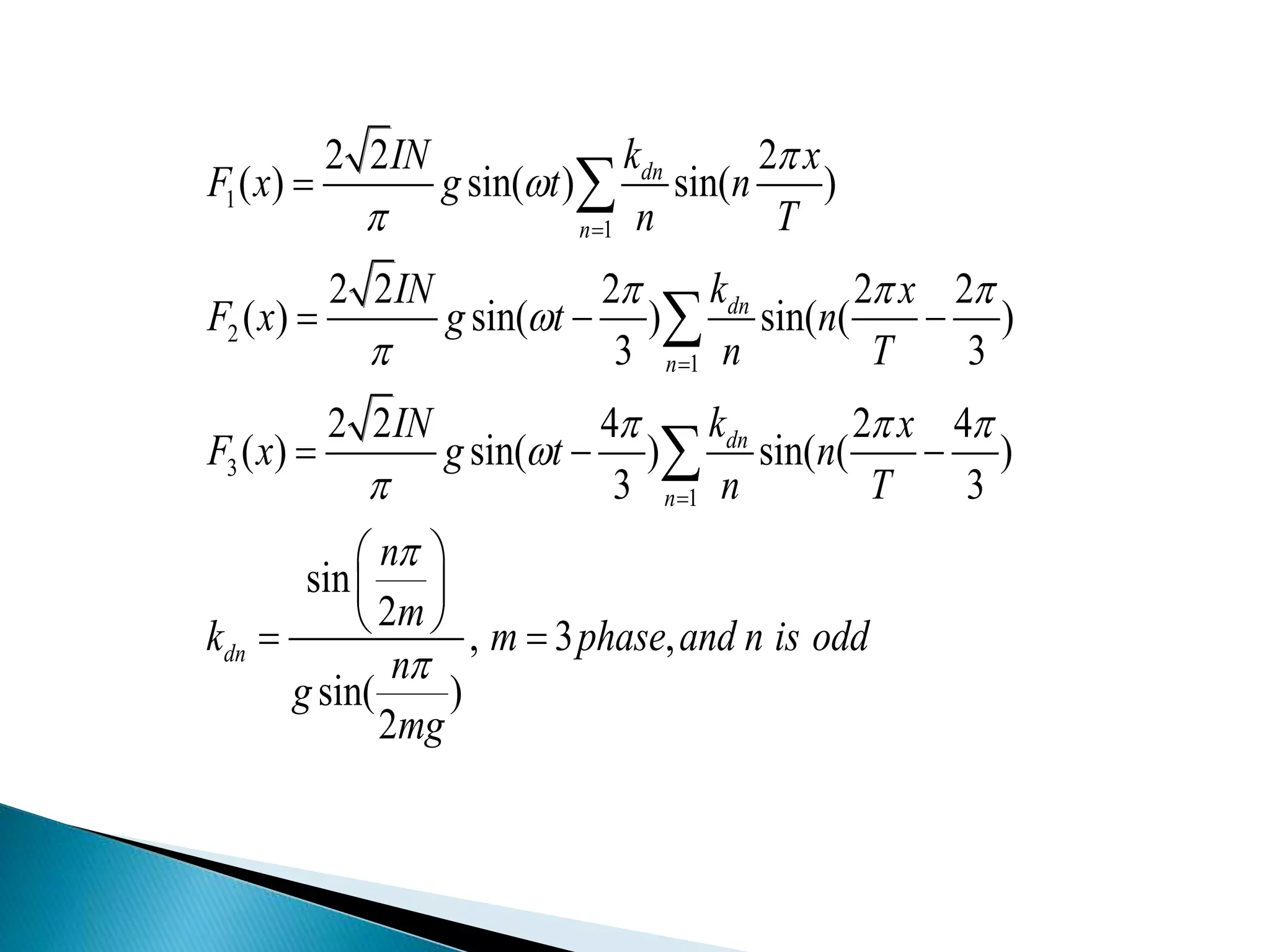
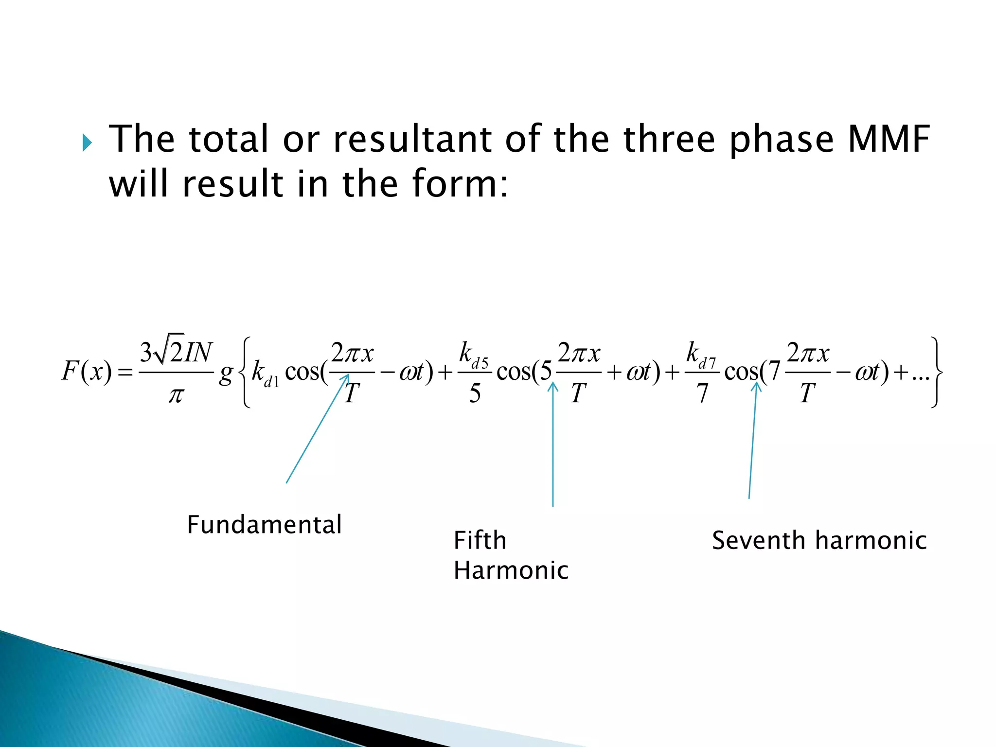
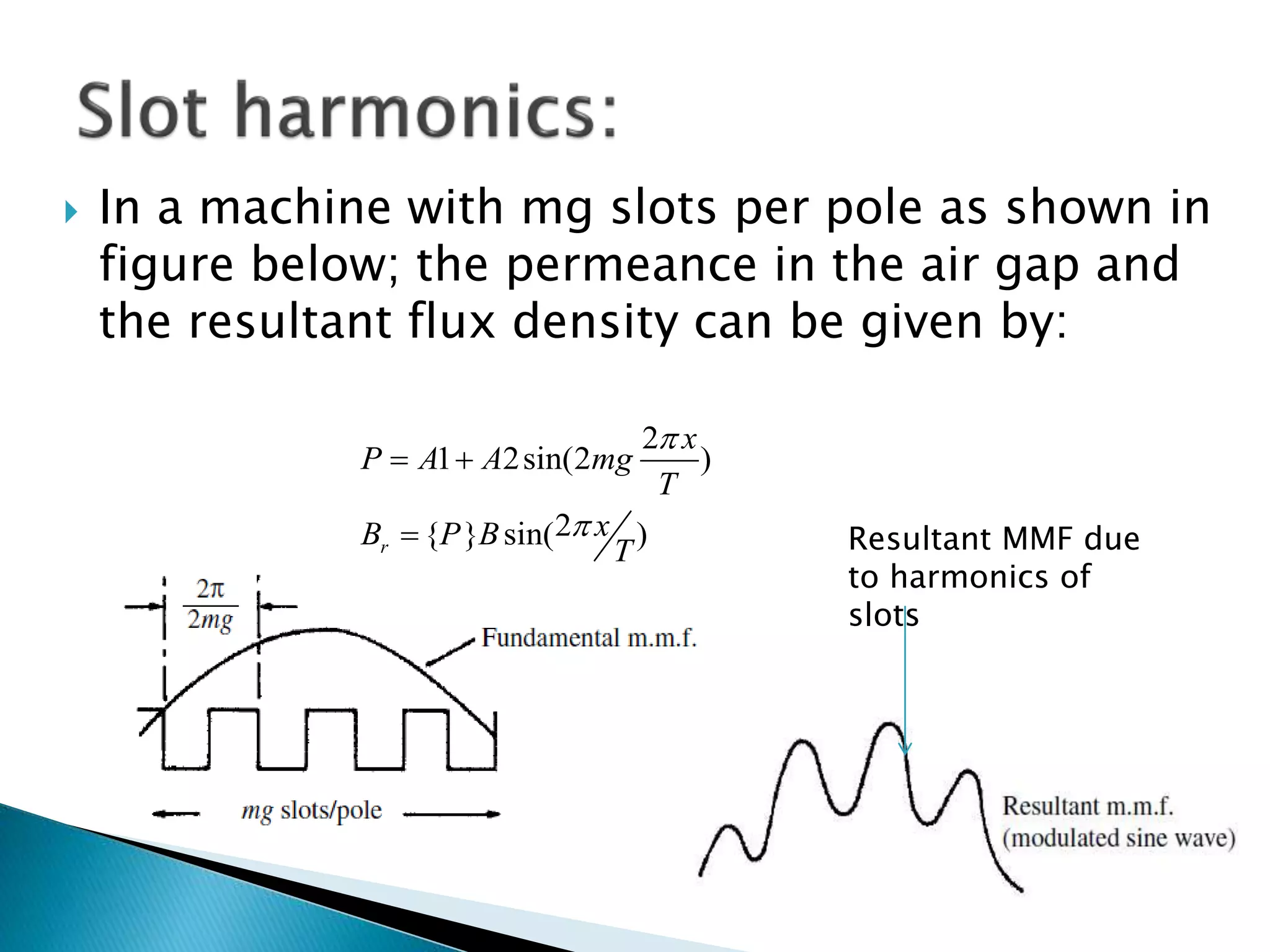
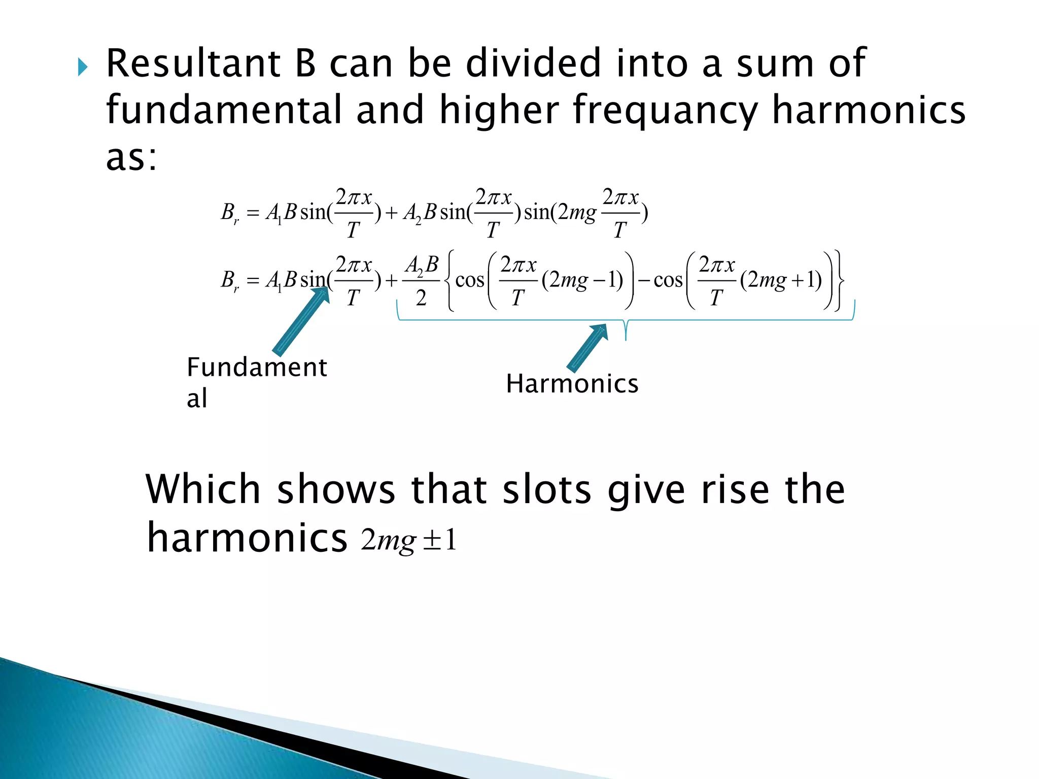
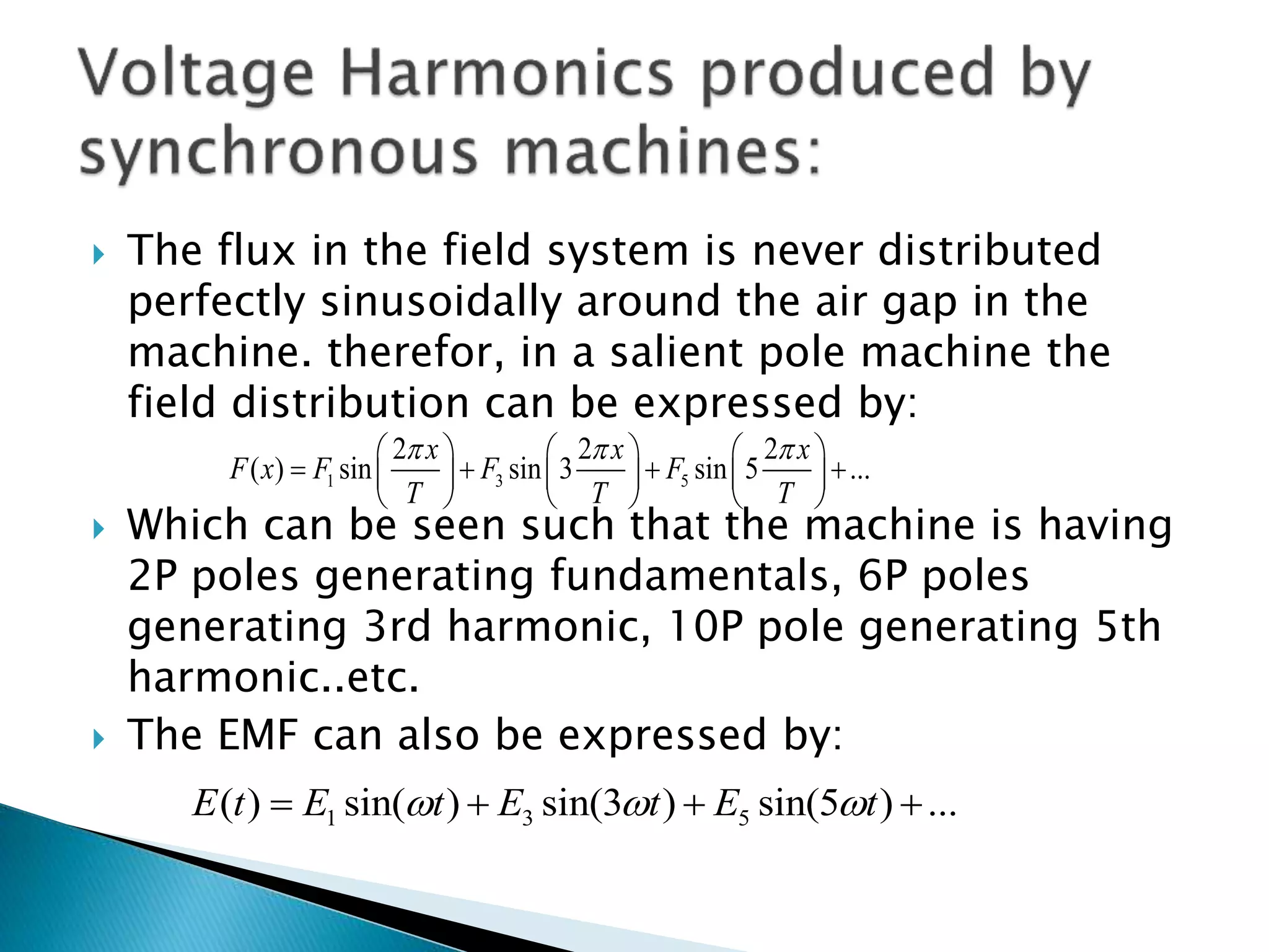
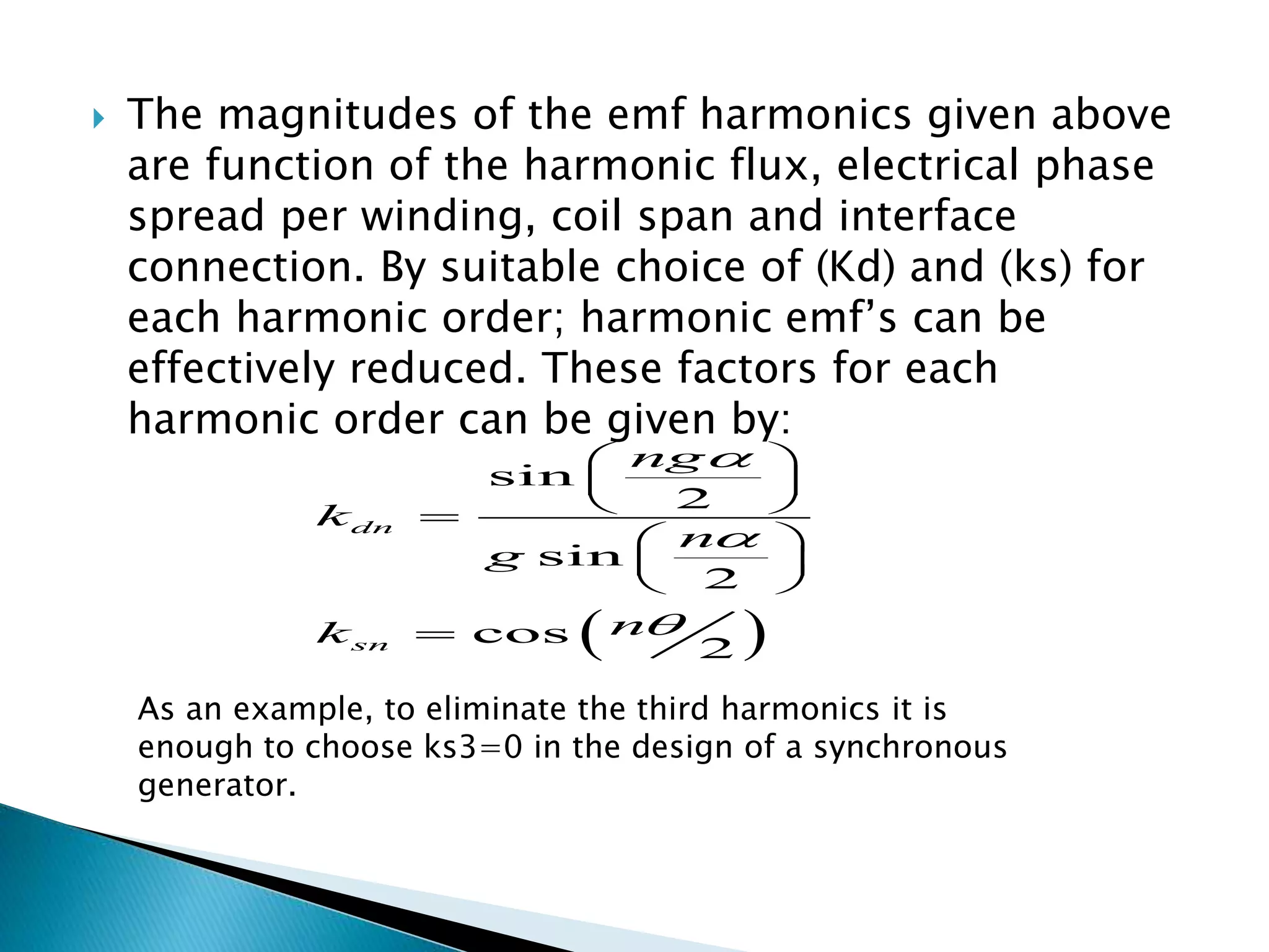
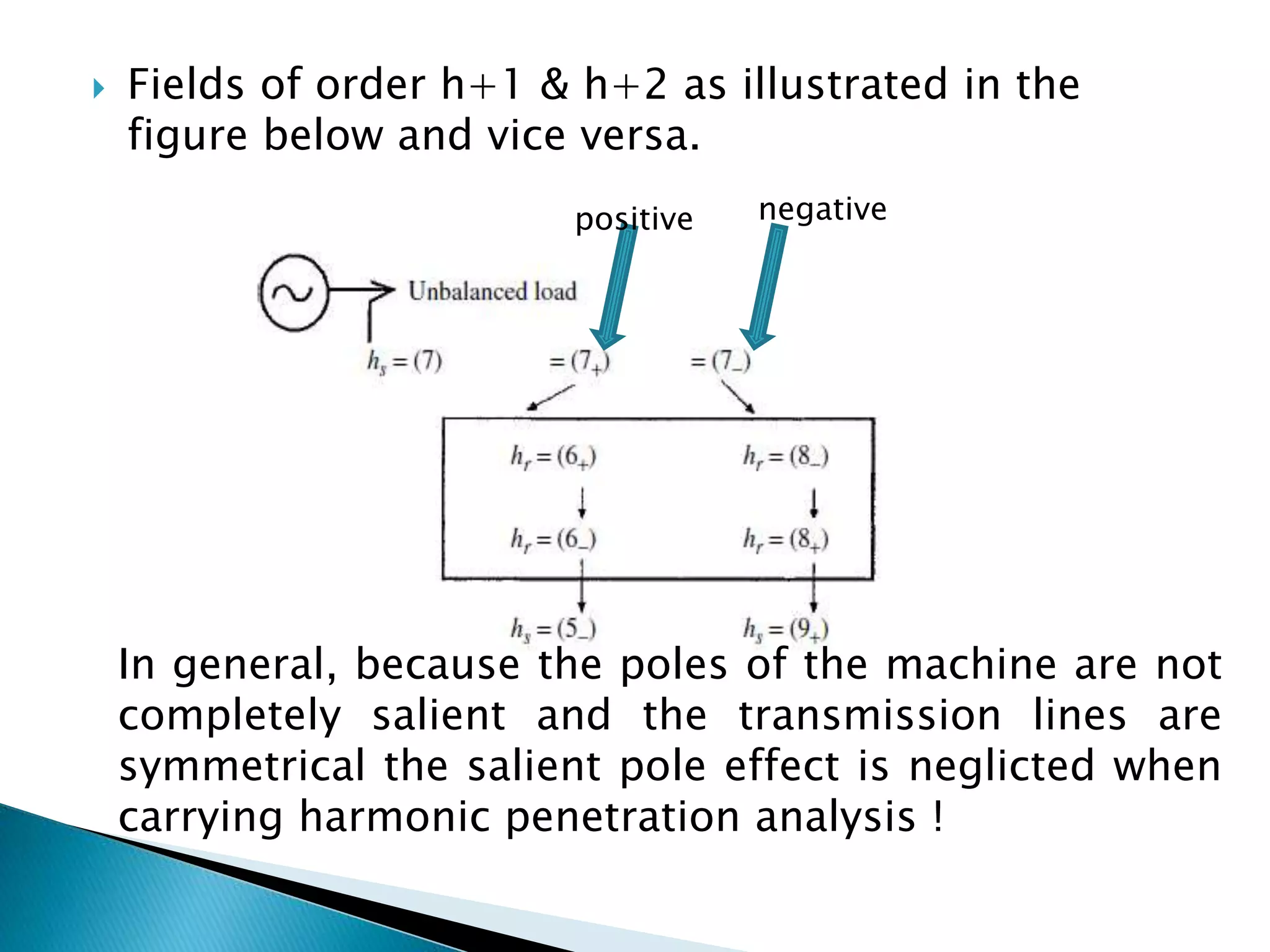
Harmonics in rotating machines
Excitaion current
MMF square
wave formSingle coil full pitched
 The square wave of the MMF can be
expressed as:
2 2 2 1 2 1 2
( ) sin( ) sin( ) sin(3 ) sin(5 ) ...
3 5
IN x x x
F x t
T T T
  


 
    
 
Where (ɪ) is the (rms) value of the excitation
current, (ω) is the excitation frequency, (T) is
the period of the square mmf. this equation
can be reduced to:
1
2 2 1 2
( ) sin( ) sin( ),
n
IN x
F x t n nisodd
n T


 
 
 In practice, windings are distributed spatially
in g slots per pole per phase of the machine.
 In a three phase machine, currents are
displaced by an angle of 120 degrees and the
windings of the machine are also displaced
spatially by 120 degrees. The MMF of each
phase can be expressed by:
1
1
2
1
3
1
2 2 2
( ) sin( ) sin( )
2 2 2 2 2
( ) sin( ) sin( ( )
3 3
2 2 4 2 4
( ) sin( ) sin( ( )
3 3
sin
2
, 3 ,
sin( )
2
dn
n
dn
n
dn
n
dn
kIN x
F x g t n
n T
kIN x
F x g t n
n T
kIN x
F x g t n
n T
n
m
k m phase and n is odd
n
g
mg



  


  








  
  
 
 
  



 The total or resultant of the three phase MMF
will result in the form:
5 7
1
3 2 2 2 2
( ) cos( ) cos(5 ) cos(7 ) ...
5 7
d d
d
k kIN x x x
F x g k t t t
T T T
  
  

 
       
 
Fundamental
Fifth
Harmonic
Seventh harmonic
 In a machine with mg slots per pole as shown in
figure below; the permeance in the air gap and
the resultant flux density can be given by:
2
1 2sin(2 )
2{ } sin( )r
x
P A A mg
T
xB P B
T


 
 Resultant MMF due
to harmonics of
slots
 Resultant B can be divided into a sum of
fundamental and higher frequancy harmonics
as:
1 2
2
1
2 2 2
sin( ) sin( )sin(2 )
2 2 2
sin( ) cos (2 1) cos (2 1)
2
r
r
x x x
B A B A B mg
T T T
A Bx x x
B A B mg mg
T T T
  
  
 
    
        
    
Fundament
al
Harmonics
Which shows that slots give rise the
harmonics 2 1mg 
 The flux in the field system is never distributed
perfectly sinusoidally around the air gap in the
machine. therefor, in a salient pole machine the
field distribution can be expressed by:
 Which can be seen such that the machine is having
2P poles generating fundamentals, 6P poles
generating 3rd harmonic, 10P pole generating 5th
harmonic..etc.
 The EMF can also be expressed by:
1 3 5
2 2 2
( ) sin sin 3 sin 5 ...
x x x
F x F F F
T T T
       
        
     
1 3 5( ) sin( ) sin(3 ) sin(5 ) ...E t E t E t E t     
 The magnitudes of the emf harmonics given above
are function of the harmonic flux, electrical phase
spread per winding, coil span and interface
connection. By suitable choice of (Kd) and (ks) for
each harmonic order; harmonic emf’s can be
effectively reduced. These factors for each
harmonic order can be given by:
 
sin
2
sin
2
cos
2
dn
sn
ng
k
n
g
nk



 
 
 
 
 
 

As an example, to eliminate the third harmonics it is
enough to choose ks3=0 in the design of a synchronous
generator.
 The flux produced by negative sequence stator current
can be divided into two counter rotating components
that induce two Emf in the stator. One of them negative
sequence at the fundamental, the other positive
sequence at the third harmonic. By consequence, the
third harmonic induced emf will produce also two
counter rotating field components that will induce 5th
harmonic. By generalisation, 7th , 9th, etc of harmonic
orders will be generated.
 The same way if the positive sequence stator current
contains a harmonic of order h and positive sequence,
the rotor flux will include two opposite rotating fields
of order h-1. these fields will induce voltages of order h
(positive sequence) and h-2 (negative sequence). The
negative sequence current h will also produce fields
 Fields of order h+1 & h+2 as illustrated in the
figure below and vice versa.
negative
In general, because the poles of the machine are not
completely salient and the transmission lines are
symmetrical the salient pole effect is neglicted when
carrying harmonic penetration analysis !
positive
 As the frequency of the rotor current in an induction
machine is a function of the slip and stator frequency
(FR=s FS); a harmonic of order n of the rotor mmf will
have a wave length of lampda/n and will induce an emf
in the stator with frequency :
Asymmetry in the rotor windings also can produce
harmonics in the stator of an induction machine due
to the presence of positive and negative sequence
currents in the unbalanced rotor.
Harmonics in rotating machines

Harmonics in rotating machines

  • 1.
  • 2.
    Excitaion current MMF square waveformSingle coil full pitched
  • 3.
     The squarewave of the MMF can be expressed as: 2 2 2 1 2 1 2 ( ) sin( ) sin( ) sin(3 ) sin(5 ) ... 3 5 IN x x x F x t T T T               Where (ɪ) is the (rms) value of the excitation current, (ω) is the excitation frequency, (T) is the period of the square mmf. this equation can be reduced to: 1 2 2 1 2 ( ) sin( ) sin( ), n IN x F x t n nisodd n T      
  • 4.
     In practice,windings are distributed spatially in g slots per pole per phase of the machine.  In a three phase machine, currents are displaced by an angle of 120 degrees and the windings of the machine are also displaced spatially by 120 degrees. The MMF of each phase can be expressed by:
  • 5.
    1 1 2 1 3 1 2 2 2 () sin( ) sin( ) 2 2 2 2 2 ( ) sin( ) sin( ( ) 3 3 2 2 4 2 4 ( ) sin( ) sin( ( ) 3 3 sin 2 , 3 , sin( ) 2 dn n dn n dn n dn kIN x F x g t n n T kIN x F x g t n n T kIN x F x g t n n T n m k m phase and n is odd n g mg                                   
  • 6.
     The totalor resultant of the three phase MMF will result in the form: 5 7 1 3 2 2 2 2 ( ) cos( ) cos(5 ) cos(7 ) ... 5 7 d d d k kIN x x x F x g k t t t T T T                    Fundamental Fifth Harmonic Seventh harmonic
  • 7.
     In amachine with mg slots per pole as shown in figure below; the permeance in the air gap and the resultant flux density can be given by: 2 1 2sin(2 ) 2{ } sin( )r x P A A mg T xB P B T      Resultant MMF due to harmonics of slots
  • 8.
     Resultant Bcan be divided into a sum of fundamental and higher frequancy harmonics as: 1 2 2 1 2 2 2 sin( ) sin( )sin(2 ) 2 2 2 sin( ) cos (2 1) cos (2 1) 2 r r x x x B A B A B mg T T T A Bx x x B A B mg mg T T T                            Fundament al Harmonics Which shows that slots give rise the harmonics 2 1mg 
  • 9.
     The fluxin the field system is never distributed perfectly sinusoidally around the air gap in the machine. therefor, in a salient pole machine the field distribution can be expressed by:  Which can be seen such that the machine is having 2P poles generating fundamentals, 6P poles generating 3rd harmonic, 10P pole generating 5th harmonic..etc.  The EMF can also be expressed by: 1 3 5 2 2 2 ( ) sin sin 3 sin 5 ... x x x F x F F F T T T                        1 3 5( ) sin( ) sin(3 ) sin(5 ) ...E t E t E t E t     
  • 10.
     The magnitudesof the emf harmonics given above are function of the harmonic flux, electrical phase spread per winding, coil span and interface connection. By suitable choice of (Kd) and (ks) for each harmonic order; harmonic emf’s can be effectively reduced. These factors for each harmonic order can be given by:   sin 2 sin 2 cos 2 dn sn ng k n g nk                 As an example, to eliminate the third harmonics it is enough to choose ks3=0 in the design of a synchronous generator.
  • 11.
     The fluxproduced by negative sequence stator current can be divided into two counter rotating components that induce two Emf in the stator. One of them negative sequence at the fundamental, the other positive sequence at the third harmonic. By consequence, the third harmonic induced emf will produce also two counter rotating field components that will induce 5th harmonic. By generalisation, 7th , 9th, etc of harmonic orders will be generated.  The same way if the positive sequence stator current contains a harmonic of order h and positive sequence, the rotor flux will include two opposite rotating fields of order h-1. these fields will induce voltages of order h (positive sequence) and h-2 (negative sequence). The negative sequence current h will also produce fields
  • 12.
     Fields oforder h+1 & h+2 as illustrated in the figure below and vice versa. negative In general, because the poles of the machine are not completely salient and the transmission lines are symmetrical the salient pole effect is neglicted when carrying harmonic penetration analysis ! positive
  • 13.
     As thefrequency of the rotor current in an induction machine is a function of the slip and stator frequency (FR=s FS); a harmonic of order n of the rotor mmf will have a wave length of lampda/n and will induce an emf in the stator with frequency : Asymmetry in the rotor windings also can produce harmonics in the stator of an induction machine due to the presence of positive and negative sequence currents in the unbalanced rotor.