Download to read offline
![Proceedings of the International Conference on Emerging Trends in Engineering and Management (ICETEM14)
30-31, December, 2014, Ernakulam, India
284
HALF BRIDGE CONVERTER WITH WIDE RANGE ZVS
AISWARYA GOPINATH 1
, JENSON JOSE 2
1
Mtech student, Jyothi engineering college, Cheruthuruthy, Kerala
2
Assistant professor, Jyothi engineering college, Cheruthuruthy, Kerala
ABSTRACT
A modified full bridge converter topology which can attain ZVS over wide load range and the circulating
current is fully eliminated. Two half bridge converters combined together to form a full bridge structure and they are
operated in phase shifted mode. The converter can perform in a 50% duty cycle which helps to achieve ZVS over wider
load range. The converter is able to perform both PWM mode as well as phase shifted mode. The switching frequency of
the converter is 100KHz.
Key words: Full Bridge Converter, Dual Half Bridge Converter, ZVS, Phase Shifting
I. INTRODUCTION
Most popular topologies for high power and high density applications in switching converter is a phase shifted
full bridge DCDC converter. Phase shifted full bridge is selected because of its capability for Zero Voltage Switching.
This configuration is mainly discussed in Texas Instruments application note. In spite of all the advantages, a problem
regarding this topology is its circulating current causing losses and ZVS not applicable for light loads.
Many methods have been introduced to added to the converter’s primary side. This helped to extend the soft
switching range but the excess energy in the converter lead to higher voltage spikes in the secondary side rectifier diodes.
By introducing a clamping circuit this problem is recovered and this captures most of the transient energy in the primary
side which is used for soft switching and is recycled back to the converter’s dc input.
For different output voltages different methods can be used to mitigate the conduction losses. Synchronous
MOSFETS are used to minimize the conduction losses for low output voltage such as 48Vor below. By maintaining
Synchronous FETs active we can achieve continuous conduction mode (CCM) and maintain constant duty cycle.
The output inductor current of the converter can be negative, positive and zero depending upon the load. In this case at
very light loads especially at zero load, negative mitigate this problem. Resonant inductor is energy become so
significant that too much energy is cycled back to the primary side resulting in efficiency loss.
When the output rectification devices are diodes it is difficult to extend ZVS range. Different circuits have been
introduced to mitigate this problem. A simple auxiliary circuit on the secondary side provides conditions for ZVZCS [4].
Another method is a passive LC network connecting to the bridge switches. [5,8].The major problem regarding of the full
bridge converter is the presence of circulating current which causes substantial power losses.
Many methods have been tried to remove this drawback. One method is resonant converters. Resonant converters will
remove circulating current but ZVS is not achieved. Another one is Asymmetrical control. This method is also applicable
for low power applications.
We all know that open loop half bridge converter is having higher efficiency at higher loads and can achieve
ZVS. The problem regarding this concept is that since PWM is fixed the output voltage cannot be regulated. If two such
converters is connected together we can achieve all the desired merits including the regulated output voltage. This
INTERNATIONAL JOURNAL OF ELECTRICAL ENGINEERING &
TECHNOLOGY (IJEET)
ISSN 0976 – 6545(Print)
ISSN 0976 – 6553(Online)
Volume 5, Issue 12, December (2014), pp. 284-288
© IAEME: www.iaeme.com/IJEET.asp
Journal Impact Factor (2014): 6.8310 (Calculated by GISI)
www.jifactor.com
IJEET
© I A E M E](https://image.slidesharecdn.com/halfbridgeconverterwithwiderangezvs-141216083734-conversion-gate02/85/Half-bridge-converter-with-wide-range-zvs-1-320.jpg)
![Proceedings of the International Conference on Emerging Trends in Engineering and Management (ICETEM14)
30-31, December, 2014, Ernakulam, India
284
HALF BRIDGE CONVERTER WITH WIDE RANGE ZVS
AISWARYA GOPINATH 1
, JENSON JOSE 2
1
Mtech student, Jyothi engineering college, Cheruthuruthy, Kerala
2
Assistant professor, Jyothi engineering college, Cheruthuruthy, Kerala
ABSTRACT
A modified full bridge converter topology which can attain ZVS over wide load range and the circulating
current is fully eliminated. Two half bridge converters combined together to form a full bridge structure and they are
operated in phase shifted mode. The converter can perform in a 50% duty cycle which helps to achieve ZVS over wider
load range. The converter is able to perform both PWM mode as well as phase shifted mode. The switching frequency of
the converter is 100KHz.
Key words: Full Bridge Converter, Dual Half Bridge Converter, ZVS, Phase Shifting
I. INTRODUCTION
Most popular topologies for high power and high density applications in switching converter is a phase shifted
full bridge DCDC converter. Phase shifted full bridge is selected because of its capability for Zero Voltage Switching.
This configuration is mainly discussed in Texas Instruments application note. In spite of all the advantages, a problem
regarding this topology is its circulating current causing losses and ZVS not applicable for light loads.
Many methods have been introduced to added to the converter’s primary side. This helped to extend the soft
switching range but the excess energy in the converter lead to higher voltage spikes in the secondary side rectifier diodes.
By introducing a clamping circuit this problem is recovered and this captures most of the transient energy in the primary
side which is used for soft switching and is recycled back to the converter’s dc input.
For different output voltages different methods can be used to mitigate the conduction losses. Synchronous
MOSFETS are used to minimize the conduction losses for low output voltage such as 48Vor below. By maintaining
Synchronous FETs active we can achieve continuous conduction mode (CCM) and maintain constant duty cycle.
The output inductor current of the converter can be negative, positive and zero depending upon the load. In this case at
very light loads especially at zero load, negative mitigate this problem. Resonant inductor is energy become so
significant that too much energy is cycled back to the primary side resulting in efficiency loss.
When the output rectification devices are diodes it is difficult to extend ZVS range. Different circuits have been
introduced to mitigate this problem. A simple auxiliary circuit on the secondary side provides conditions for ZVZCS [4].
Another method is a passive LC network connecting to the bridge switches. [5,8].The major problem regarding of the full
bridge converter is the presence of circulating current which causes substantial power losses.
Many methods have been tried to remove this drawback. One method is resonant converters. Resonant converters will
remove circulating current but ZVS is not achieved. Another one is Asymmetrical control. This method is also applicable
for low power applications.
We all know that open loop half bridge converter is having higher efficiency at higher loads and can achieve
ZVS. The problem regarding this concept is that since PWM is fixed the output voltage cannot be regulated. If two such
converters is connected together we can achieve all the desired merits including the regulated output voltage. This
INTERNATIONAL JOURNAL OF ELECTRICAL ENGINEERING &
TECHNOLOGY (IJEET)
ISSN 0976 – 6545(Print)
ISSN 0976 – 6553(Online)
Volume 5, Issue 12, December (2014), pp. 284-288
© IAEME: www.iaeme.com/IJEET.asp
Journal Impact Factor (2014): 6.8310 (Calculated by GISI)
www.jifactor.com
IJEET
© I A E M E](https://image.slidesharecdn.com/halfbridgeconverterwithwiderangezvs-141216083734-conversion-gate02/75/Half-bridge-converter-with-wide-range-zvs-1-2048.jpg)
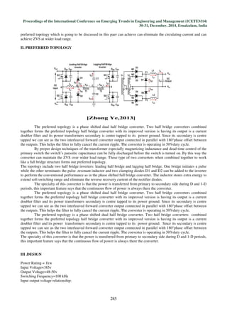
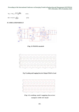
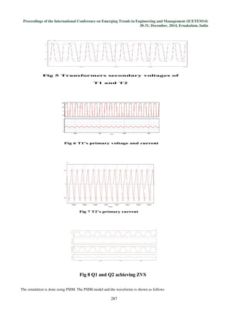

The document summarizes a new converter topology called a phase shifted dual half bridge converter. Two key advantages of this topology are: 1) It can achieve zero voltage switching over a wide load range by operating the two half bridges in a phase shifted manner at 50% duty cycle. 2) It eliminates circulating current that is normally present in full bridge topologies by combining the outputs of the two half bridges with 180 degree phase offset. The converter was designed with a power rating of 1kW and simulated in PSIM software, demonstrating the benefits of wide ZVS range and no circulating current.


![6.[36 45]seven level modified cascaded inverter for induction motor drive app...](https://cdn.slidesharecdn.com/ss_thumbnails/6-36-45sevenlevelmodifiedcascadedinverterforinductionmotordriveapplications-111118181646-phpapp02-thumbnail.jpg?width=640&height=640&fit=bounds)