Download to read offline
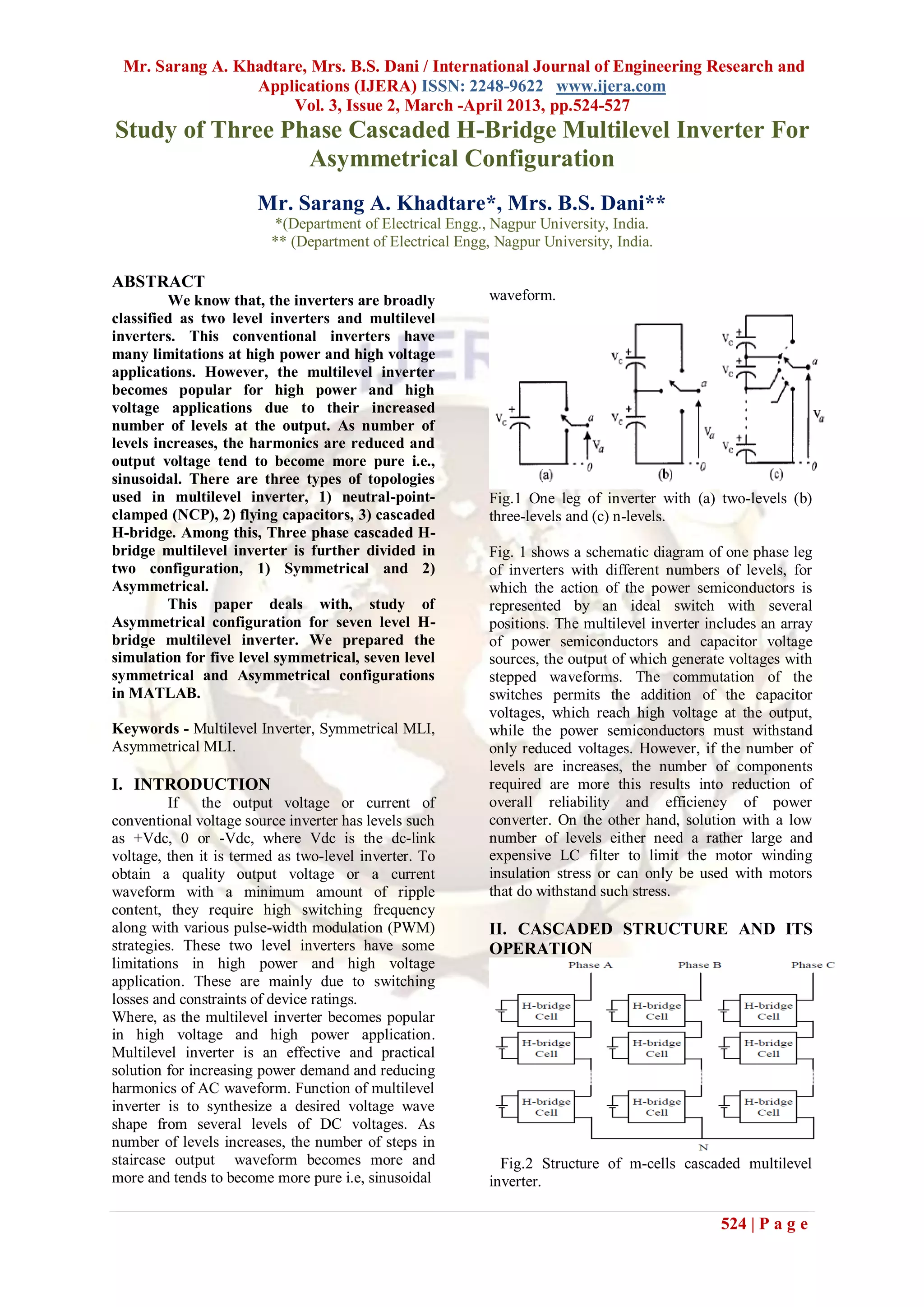
![Mr. Sarang A. Khadtare, Mrs. B.S. Dani / International Journal of Engineering Research and
Applications (IJERA) ISSN: 2248-9622 www.ijera.com
Vol. 3, Issue 2, March -April 2013, pp.524-527
REFERENCES
300 [1] ''Power Electronics'' Circuits, Devices,
And Applications, 3rd Edition by
Muhammad H. Rashid.
200 [2] Bipin Singh, KP Singh and AN Tiwari,
''Modelling of 5-Level Inverter
Phase Voltage (Volts)
Controlled With DVR Technique'',
100 VSRD-IJEECE, Vol. 2 (1), 2012, 16-21.
[3] F. Khoucha, M. S Lagoun, K. Marouani,
A. Kheloui, and M.E.H. Benbouzid,
0 “Hybrid cascaded H-bridge multilevel
inverter induction motor drive direct
torque control for automotive
-100
applications,” IEEE Trans. Ind. Electron.,
vol. 57, no.3,pp.892–899, Mar. 2010.
-200 [4] Farid Khoucha, Mouna Soumia Lagoun,
Abdelaziz Kheloui, and Mohamed El
Hachemi Benbouzid, Senior Member, "A
-300 Comparison of Symmetrical and
0 0.16 0.33 0.49 0.66 0.83 1 Asymmetrical Three-Phase H-Bridge
Time(Sec) Multilevel Inverter for DTC Induction
Motor Drives'', IEEE TRANSACTIONS
(A) ON ENERGY CONVERSION, VOL. 26,
NO. 1, MARCH 2011.
600 [5] K.Surya Suresh1 and M.Vishnu Prasad,
Sri Vasavi Institute of Engineering and
Technology, EEE Department,
400 Nandamuru, AP, India "PV Cell Based
Five Level Inverter Using Multicarrier
PWM" International Journal of Modern
Line Voltage (Volts)
200 Engineering Research (IJMER) Vol.1,
Issue.2, pp-545-551.
[6] Bindeshwar Singh, Nupur Mittal , Dr.
0 K.S. Verma , Dr. Deependra Singh,
S.P.Singh, Rahul Dixit, Manvendra Singh,
Aanchal Baranwa, "Multi-level inverter:
A literature survey on topologies and
-200 control strategies" International Journal
of Reviews in Computing 31st July 2012.
Vol. 10.
-400 [7] Jannu Ramu1, S.J.V. Prakash, K.Satya
Srinivasu1, R.N.D. Pattabhi Ram, M.
Vishnu Prasad and Md. Mazhar
-600 Hussain,''Comparison between
0 0.16 0.33 0.49 0.66 0.83 1 Symmetrical and Asymmetrical Single
Time (Sec) Phase Seven Level Cascade H-Bridge
(B) Multilevel Inverter with PWM
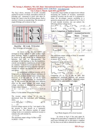
Fig.7 Simulation Results For 7- Level Asymmetric Topology." International Journal of
Cascaded H-Bridge Multilevel Inverter, A) Phase Multidisciplinary Sciences and
Voltage; B) Line Voltage. Engineering, Vol. 3, No. 4, April 2012.
IV. CONCLUSION
From above waveforms and table we
concluded that, the Asymmetrical inverter is able to
produce same value of output voltage but with
more number of levels thus the output voltage has
less harmonics and it is more pure than
Symmetrical one. The number of bridges and DC
sources, switching losses are also reduced in
asymmetric MLI as compared to symmetrical.
527 | P a g e](https://image.slidesharecdn.com/ch32524527-130322063133-phpapp01/85/Ch32524527-4-320.jpg)

This document discusses cascaded H-bridge multilevel inverters and their symmetrical and asymmetrical configurations. It begins by introducing two-level and multilevel inverters, noting that multilevel inverters are better suited for high power and voltage applications as they reduce harmonics. There are three main multilevel inverter topologies: neutral-point-clamped, flying capacitors, and cascaded H-bridges. The cascaded H-bridge topology connects H-bridge cells in series to generate stepped voltage waveforms. Symmetrical configurations use equal DC voltages for each cell, while asymmetrical configurations use unequal voltages, allowing more voltage levels with the same number of cells. The document presents simulations of


![6.[36 45]seven level modified cascaded inverter for induction motor drive app...](https://cdn.slidesharecdn.com/ss_thumbnails/6-36-45sevenlevelmodifiedcascadedinverterforinductionmotordriveapplications-111118181646-phpapp02-thumbnail.jpg?width=640&height=640&fit=bounds)

![6.[36 45]seven level modified cascaded inverter for induction motor drive app...](https://cdn.slidesharecdn.com/ss_thumbnails/6-36-45sevenlevelmodifiedcascadedinverterforinductionmotordriveapplications-111203185124-phpapp02-thumbnail.jpg?width=640&height=640&fit=bounds)


