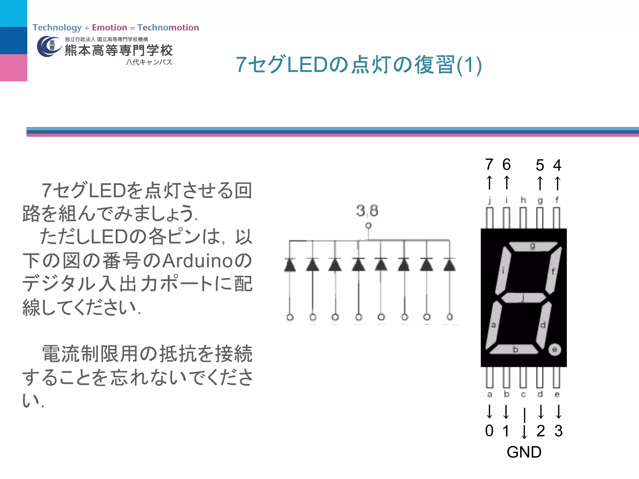
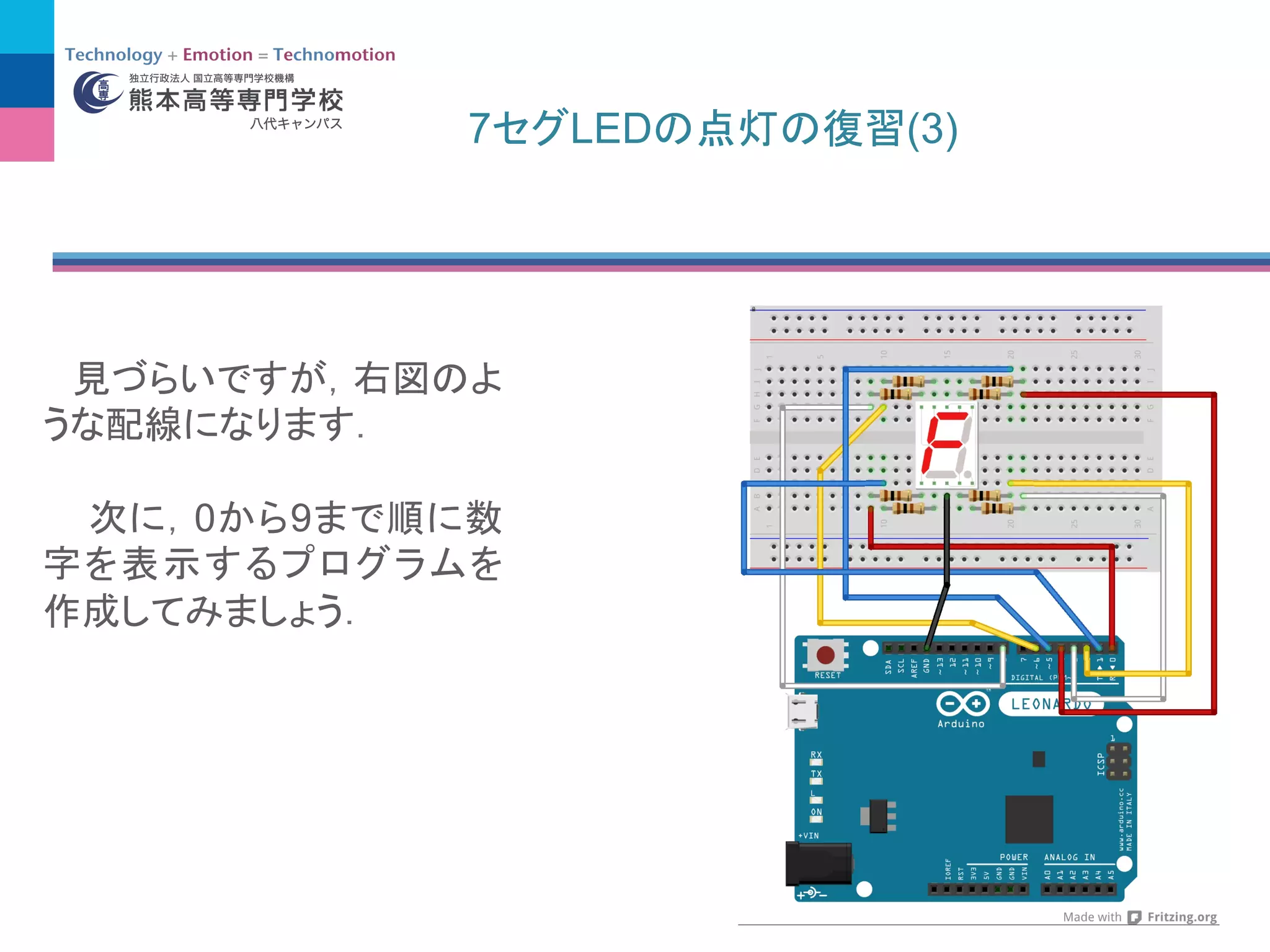
7 LED (3)
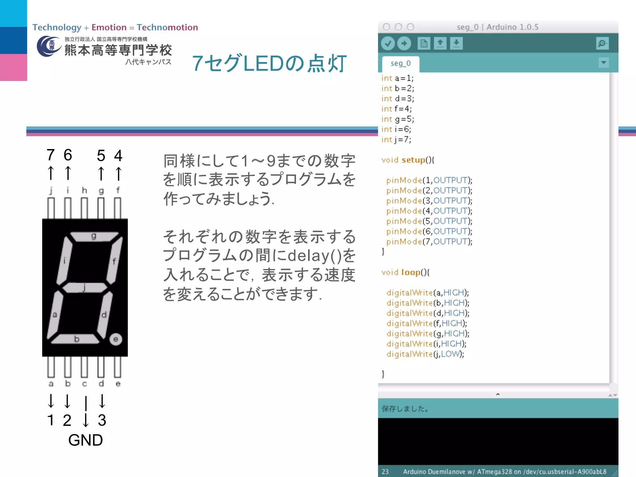
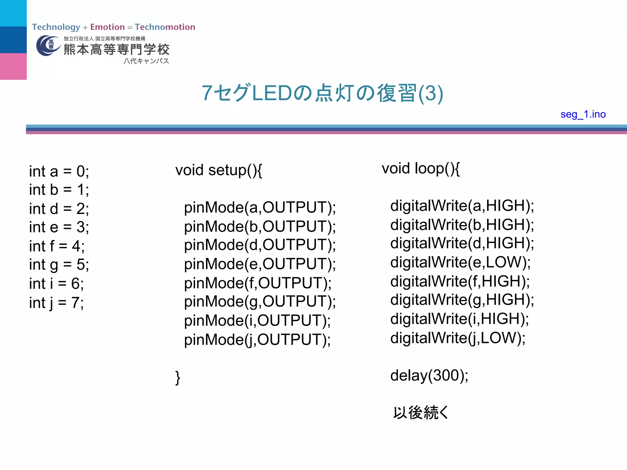
inta = 0;
int b = 1;
int d = 2;
int e = 3;
int f = 4;
int g = 5;
int i = 6;
int j = 7;
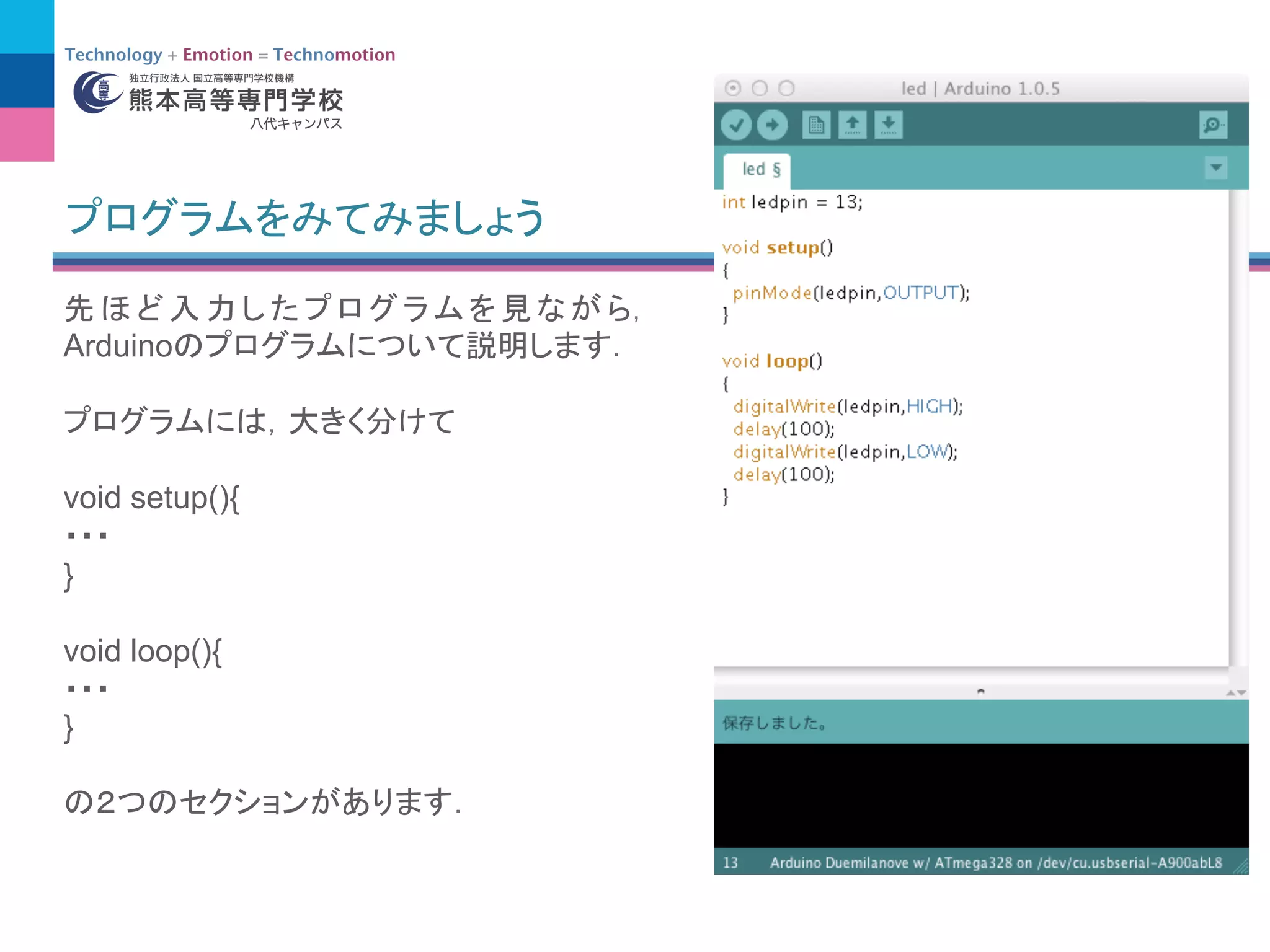
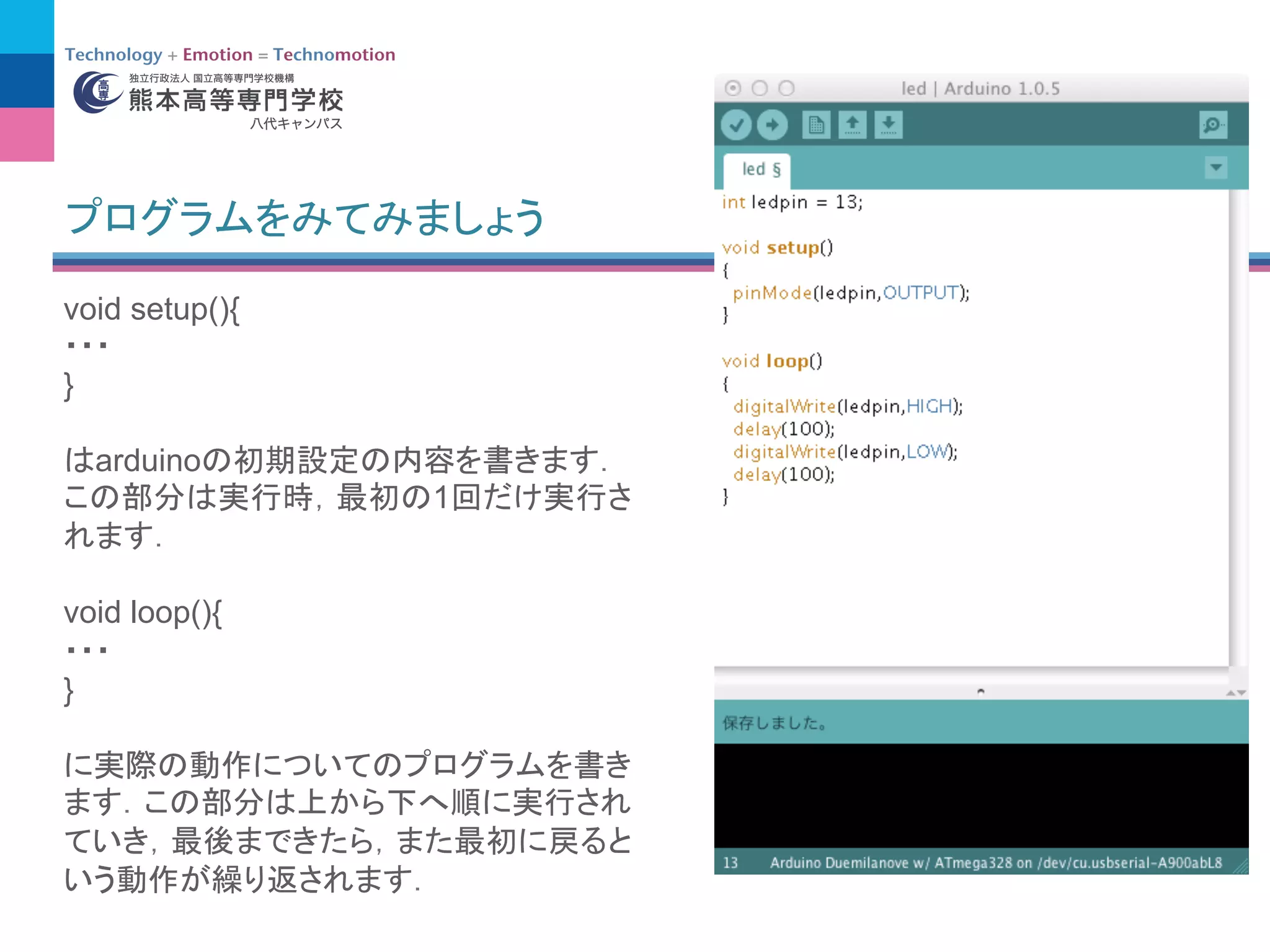
void setup(){
pinMode(a,OUTPUT);
pinMode(b,OUTPUT);
pinMode(d,OUTPUT);
pinMode(e,OUTPUT);
pinMode(f,OUTPUT);
pinMode(g,OUTPUT);
pinMode(i,OUTPUT);
pinMode(j,OUTPUT);
}
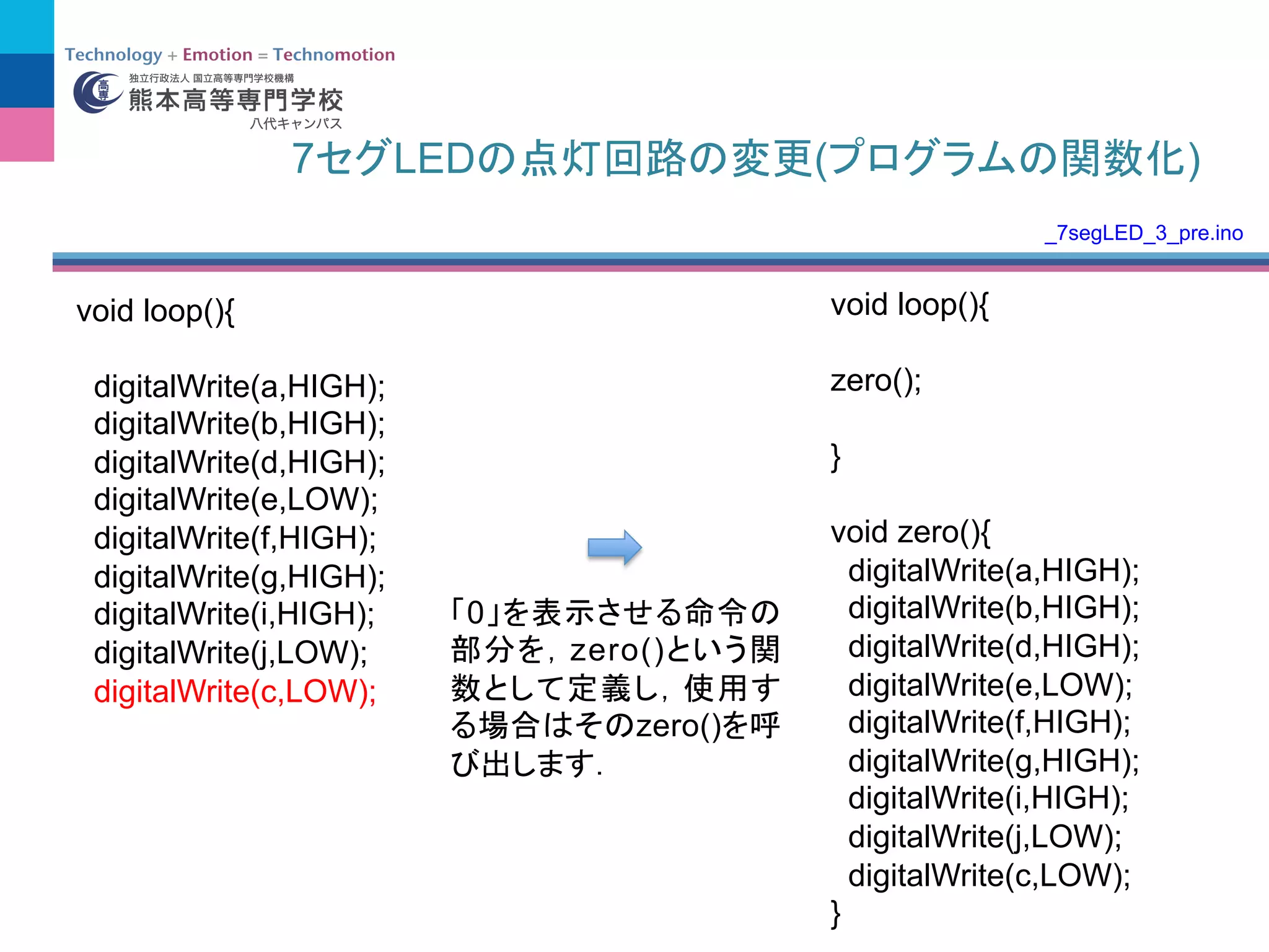
void loop(){
digitalWrite(a,HIGH);
digitalWrite(b,HIGH);
digitalWrite(d,HIGH);
digitalWrite(e,LOW);
digitalWrite(f,HIGH);
digitalWrite(g,HIGH);
digitalWrite(i,HIGH);
digitalWrite(j,LOW);
delay(300);
seg_1.ino
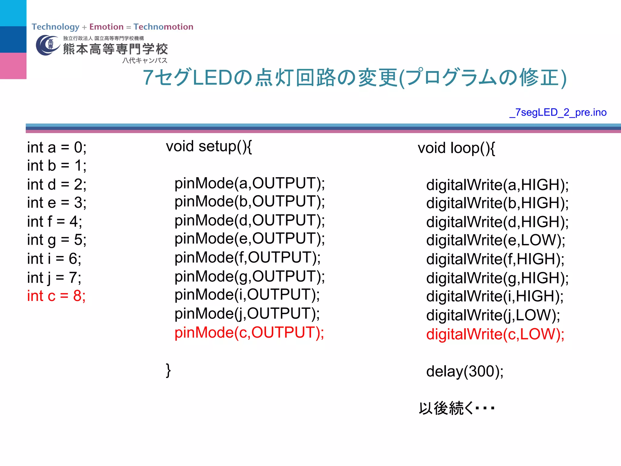
int a =0;
int b = 1;
int d = 2;
int e = 3;
int f = 4;
int g = 5;
int i = 6;
int j = 7;
int c = 8;
void loop(){
digitalWrite(a,HIGH);
digitalWrite(b,HIGH);
digitalWrite(d,HIGH);
digitalWrite(e,LOW);
digitalWrite(f,HIGH);
digitalWrite(g,HIGH);
digitalWrite(i,HIGH);
digitalWrite(j,LOW);
digitalWrite(c,LOW);
delay(300);
void setup(){
pinMode(a,OUTPUT);
pinMode(b,OUTPUT);
pinMode(d,OUTPUT);
pinMode(e,OUTPUT);
pinMode(f,OUTPUT);
pinMode(g,OUTPUT);
pinMode(i,OUTPUT);
pinMode(j,OUTPUT);
pinMode(c,OUTPUT);
}
7 LED ( )
_7segLED_2_pre.ino
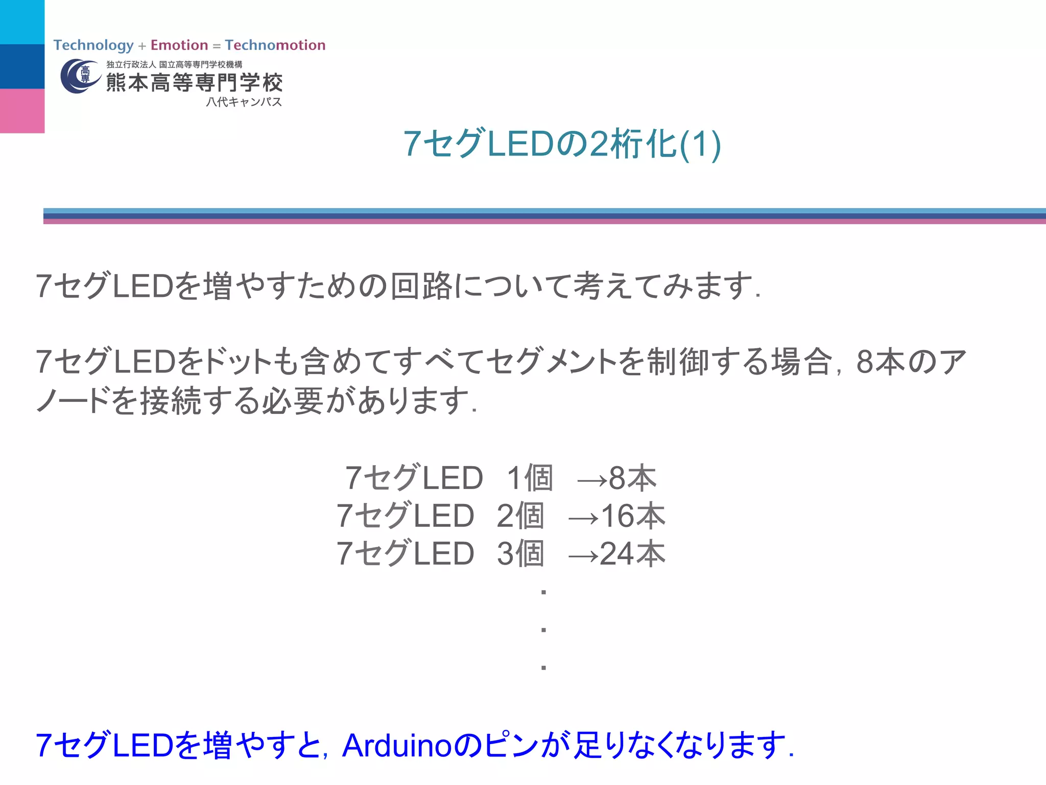
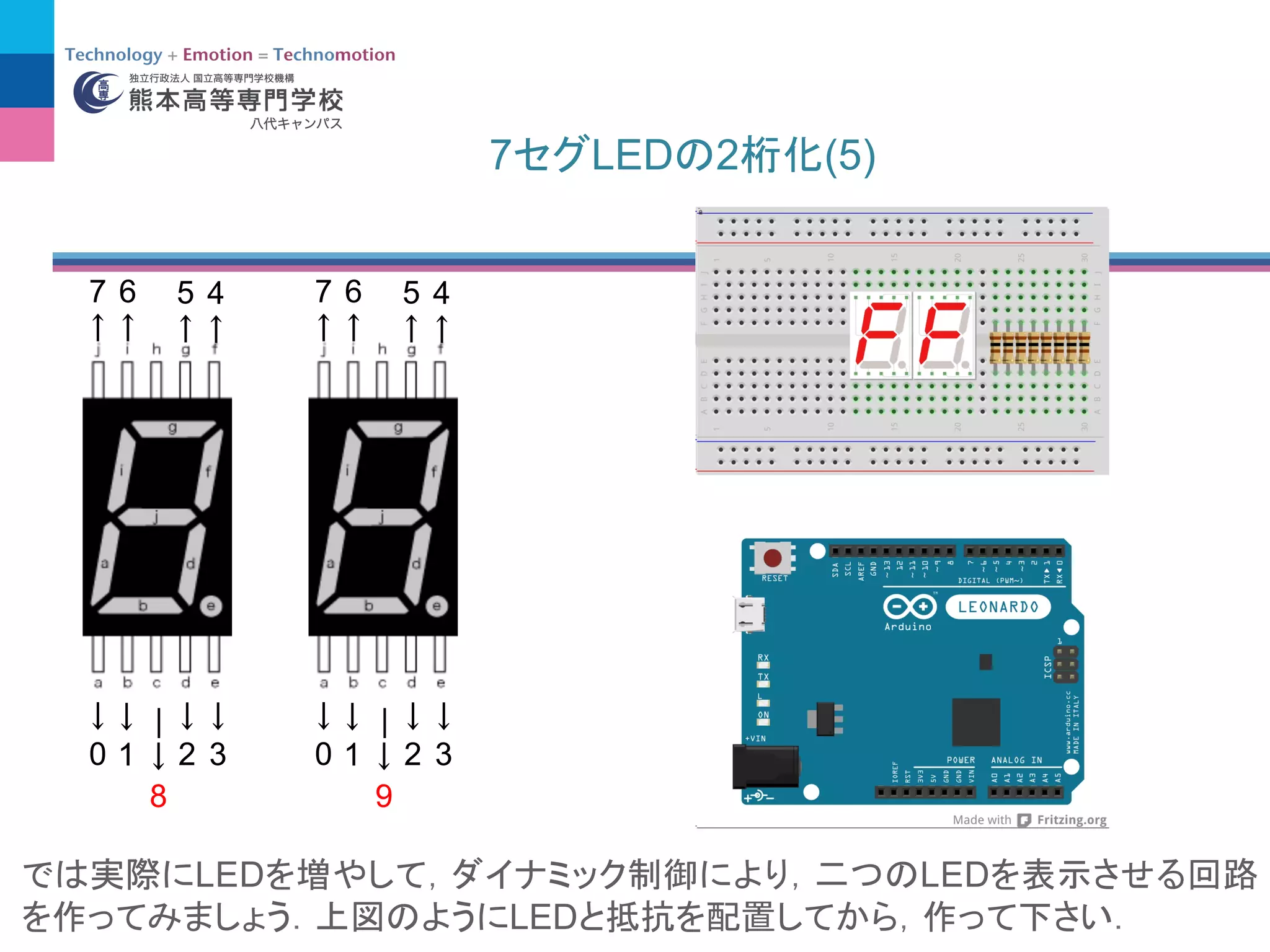
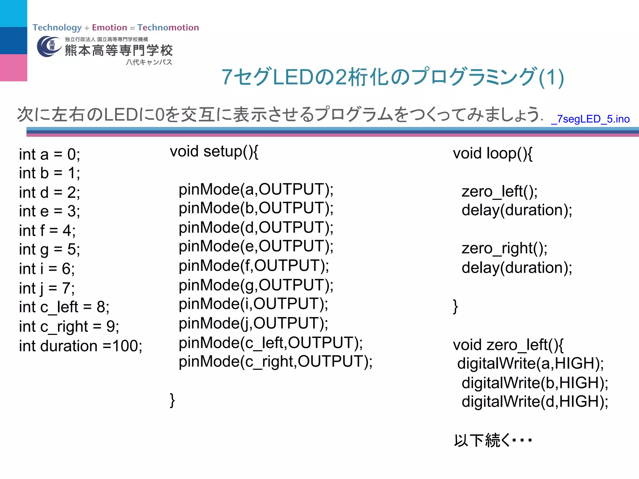
7 LED 2(1)
int a = 0;
int b = 1;
int d = 2;
int e = 3;
int f = 4;
int g = 5;
int i = 6;
int j = 7;
int c_left = 8;
int c_right = 9;
int duration =100;
LED 0
void setup(){
pinMode(a,OUTPUT);
pinMode(b,OUTPUT);
pinMode(d,OUTPUT);
pinMode(e,OUTPUT);
pinMode(f,OUTPUT);
pinMode(g,OUTPUT);
pinMode(i,OUTPUT);
pinMode(j,OUTPUT);
pinMode(c_left,OUTPUT);
pinMode(c_right,OUTPUT);
}
void loop(){
zero_left();
delay(duration);
zero_right();
delay(duration);
}
void zero_left(){
digitalWrite(a,HIGH);
digitalWrite(b,HIGH);
digitalWrite(d,HIGH);
_7segLED_5.ino
56.
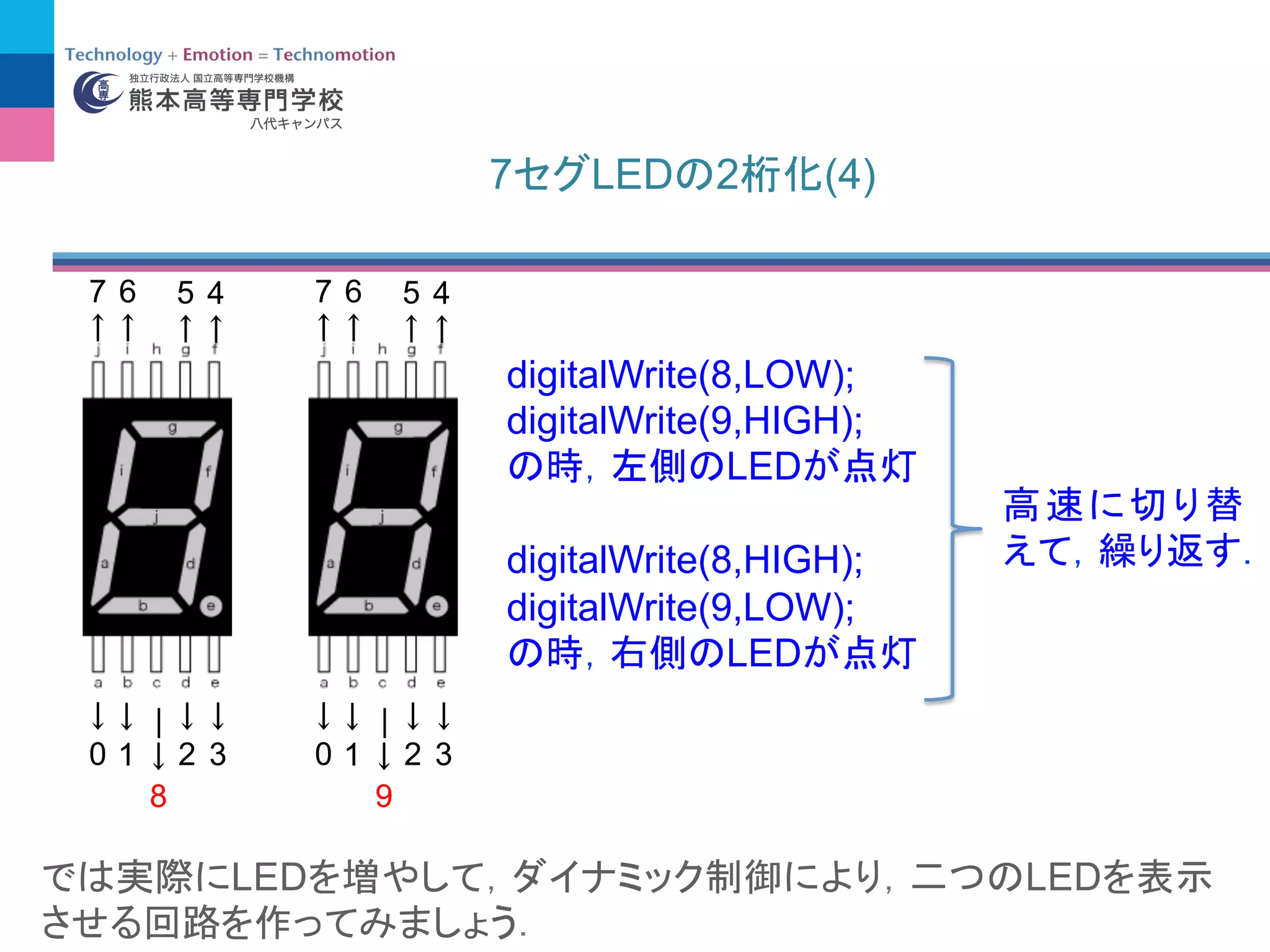
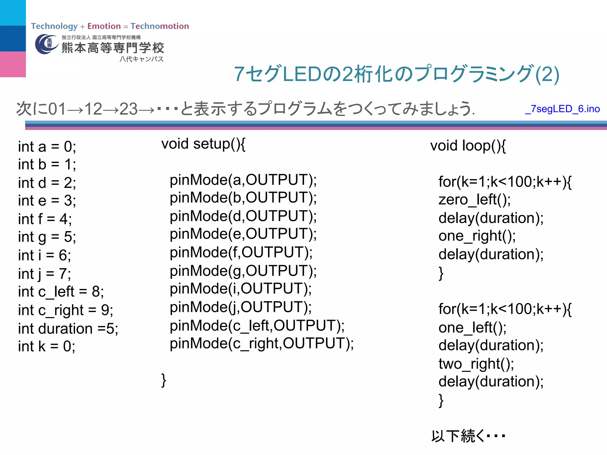
7 LED 2(2)
int a = 0;
int b = 1;
int d = 2;
int e = 3;
int f = 4;
int g = 5;
int i = 6;
int j = 7;
int c_left = 8;
int c_right = 9;
int duration =5;
int k = 0;
void setup(){
pinMode(a,OUTPUT);
pinMode(b,OUTPUT);
pinMode(d,OUTPUT);
pinMode(e,OUTPUT);
pinMode(f,OUTPUT);
pinMode(g,OUTPUT);
pinMode(i,OUTPUT);
pinMode(j,OUTPUT);
pinMode(c_left,OUTPUT);
pinMode(c_right,OUTPUT);
}
void loop(){
for(k=1;k<100;k++){
zero_left();
delay(duration);
one_right();
delay(duration);
}
for(k=1;k<100;k++){
one_left();
delay(duration);
two_right();
delay(duration);
}
01→12→23→ _7segLED_6.ino
スケッチの例 RowColumnScanning を使用
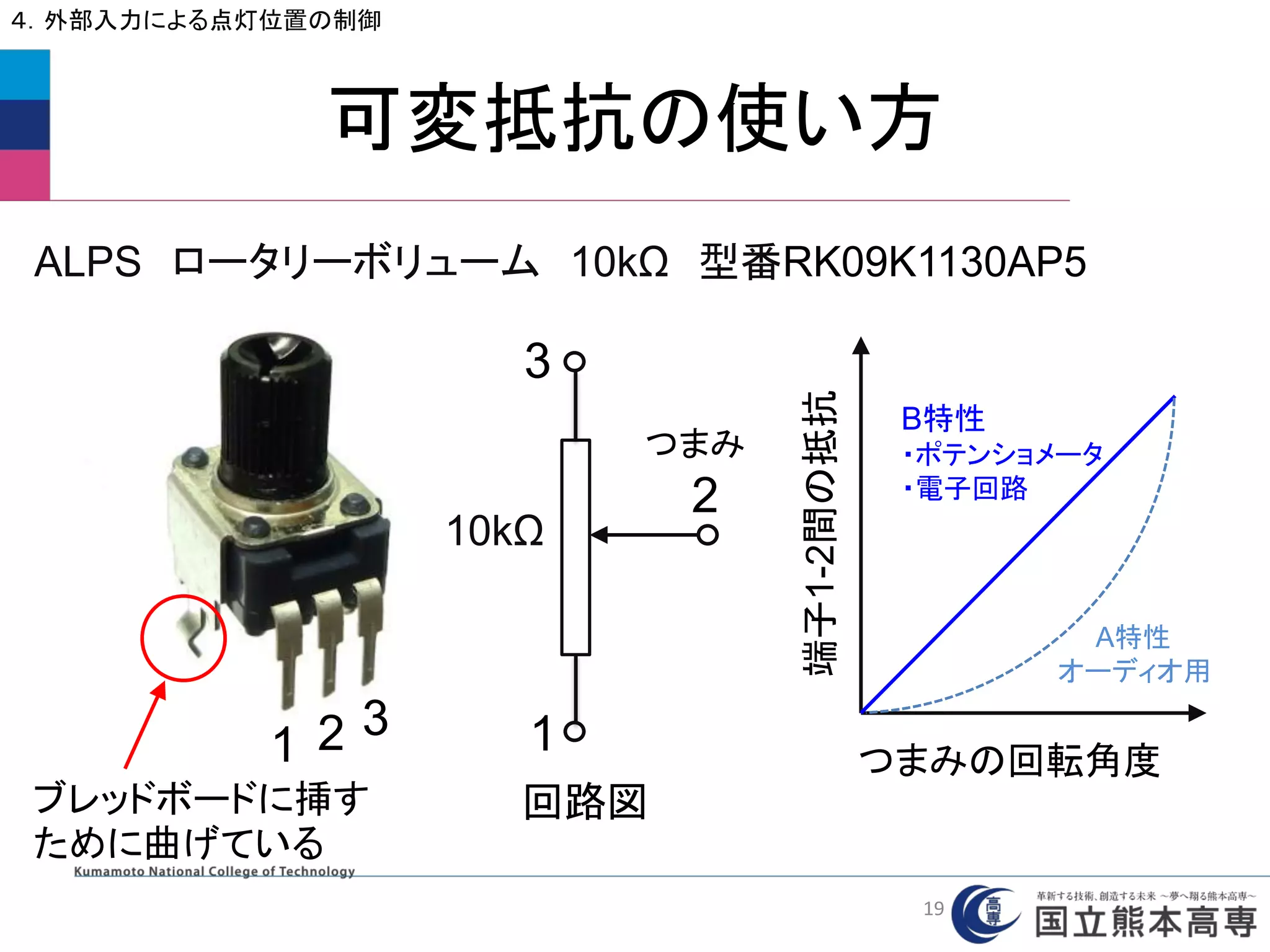
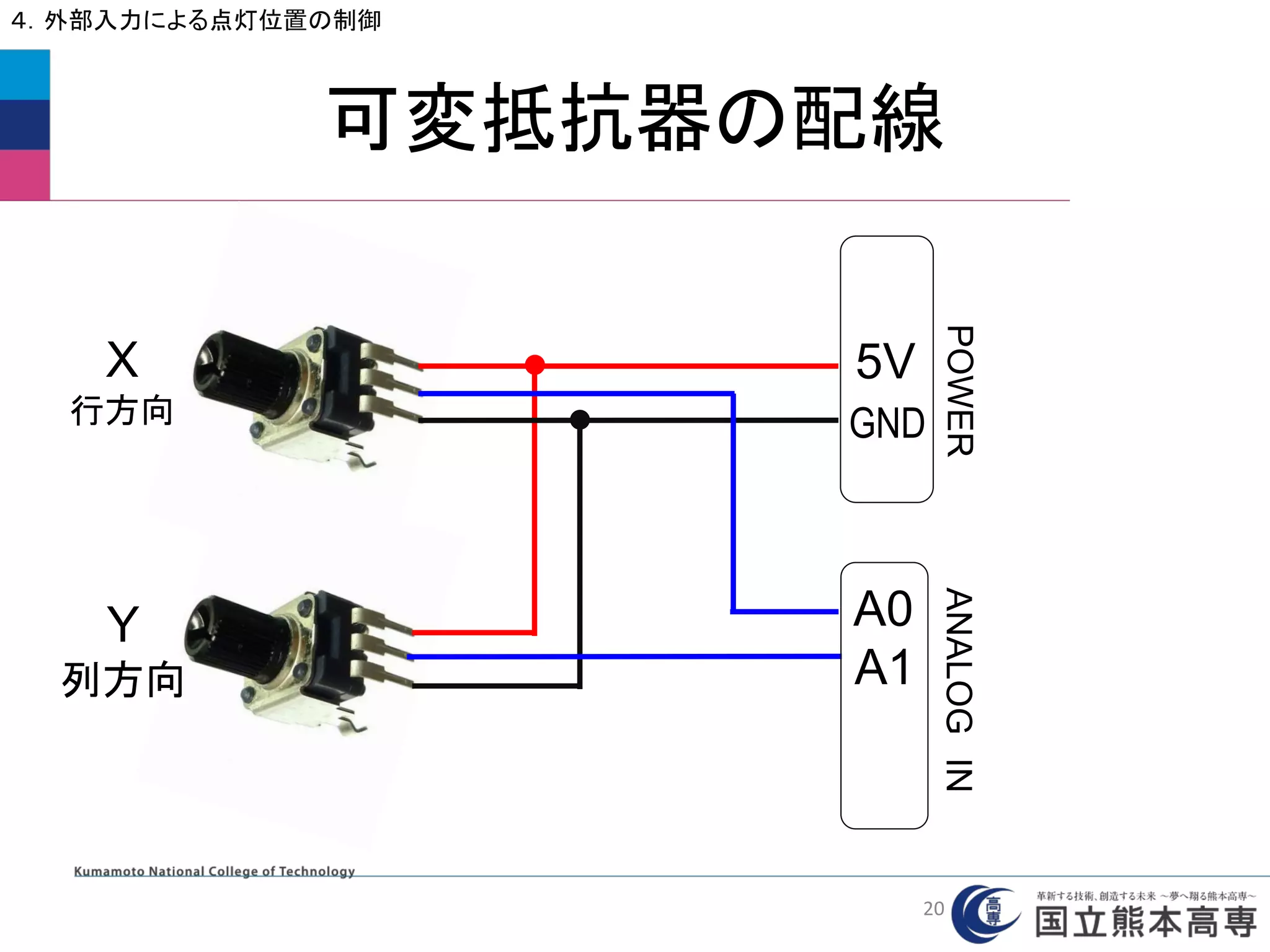
4.外部入力による点灯位置の制御
(1)ファイル ⇒ スケッチの例 ⇒ 07.Display ⇒
RowColumnScanning を選択
(2) Arduino UNO のピン番号をLEONALD仕様に変更
// 2-dimensional array of row pin numbers:
const int row[8] = {2,7,19,5,13,18,12,16 } を
const int row[8] = {2,7,23,5,13,22,12,20 } に変更
// 2-dimensional array of column pin numbers:
const int col[8] = {6,11,10,3,17,4,8,9 } を
const int col[8] = {6,11,10,3,21,4,8,9 } に変更
21
90.
RowColumnScanning
4.外部入力による点灯位置の制御
// 2-dimensional arrayof pixels:
int pixels[8][8]; // ドットマトリクスLED用の
8×8の二次元配列を準備
// cursor position:
int x = 5; //LEDのx軸(行方向)の位置を決める変数 ⇒ pixelsのx番地
int y = 5; //LEDのy軸(列方向)の位置を決める変数 ⇒ pixelsのy番地
// initialize the pixel matrix:
for (int x = 0; x < 8; x++) {
for (int y = 0; y < 8; y++) {
pixels[x][y] = HIGH; //配列pixelsの中身をすべてHIGHに初期化
}
}
void setup( )は省略
0
1
2
3
4
5
6
7
yの番地
xの番地
0 1 2 3 4 5 6 7
22
91.
void readSensors() {
//turn off the last position:
pixels[x][y] = HIGH; // 配列pixelsの番地(x,y:前の番地)の中身をHIGHに設定
// read the sensors for X and Y values:
x = 7 - map(analogRead(A0), 0, 1023, 0, 7); //入力電圧を0~7へ変換し,
それを7から引いたものをx
y = map(analogRead(A1), 0, 1023, 0, 7); //入力電圧を0~7へ変換し,それをy
// set the new pixel position low so that the LED will turn on
// in the next screen refresh:
pixels[x][y] = LOW; // 配列pixelsの番地(x,y:現在の番地)の中身をLOWに設定
}
RowColumnScanning
4.外部入力による点灯位置の制御
A0の電圧を取得 現在の範囲 新しい範囲
0
1
2
3
4
5
6
7
yの番地
xの番地
0 1 2 3 4 5 6 7
readSensors()は,可変抵抗のつまみの位置を
電圧として読み込み,その値によって点灯位置の番
地x,y を決め,そこがONになるように配列pixelsに
LOWをセットする.
23
92.
RowColumnScanning
4.外部入力による点灯位置の制御
void refreshScreen() {//pixel[x][y]をスキャンしてLOWの位置でLEDを点灯させ,すぐに消す
// iterate over the rows (anodes):
for (int thisRow = 0; thisRow < 8; thisRow++) { // 行の繰り返し
// take the row pin (anode) high:
digitalWrite(row[thisRow], HIGH); // thisRow番目の行をHIGHにする(ONの準備)
// iterate over the cols (cathodes):
for (int thisCol = 0; thisCol < 8; thisCol++) { // 列の繰り返し
// get the state of the current pixel;
int thisPixel = pixels[thisRow][thisCol]; // thisPixel に 現在のpixels[thisRow][thisCol] の中身を代入
// when the row is HIGH and the col is LOW,
// the LED where they meet turns on:
digitalWrite(col[thisCol], thisPixel); // thisCol列 に thisPixel の値をデジタル出力
(thisPixel が LOW のところだけ LED ON)
// turn the pixel off:
if (thisPixel == LOW) { // もし thisPixel の中身が LOW ならば次を実行
digitalWrite(col[thisCol], HIGH); // thisCol列に HIGH を出力(LED OFF)
}
}
// take the row pin low to turn off the whole row:
digitalWrite(row[thisRow], LOW); // thisRow番目の行をLOWにする(OFFに戻す)
}
}
点灯
消灯
24
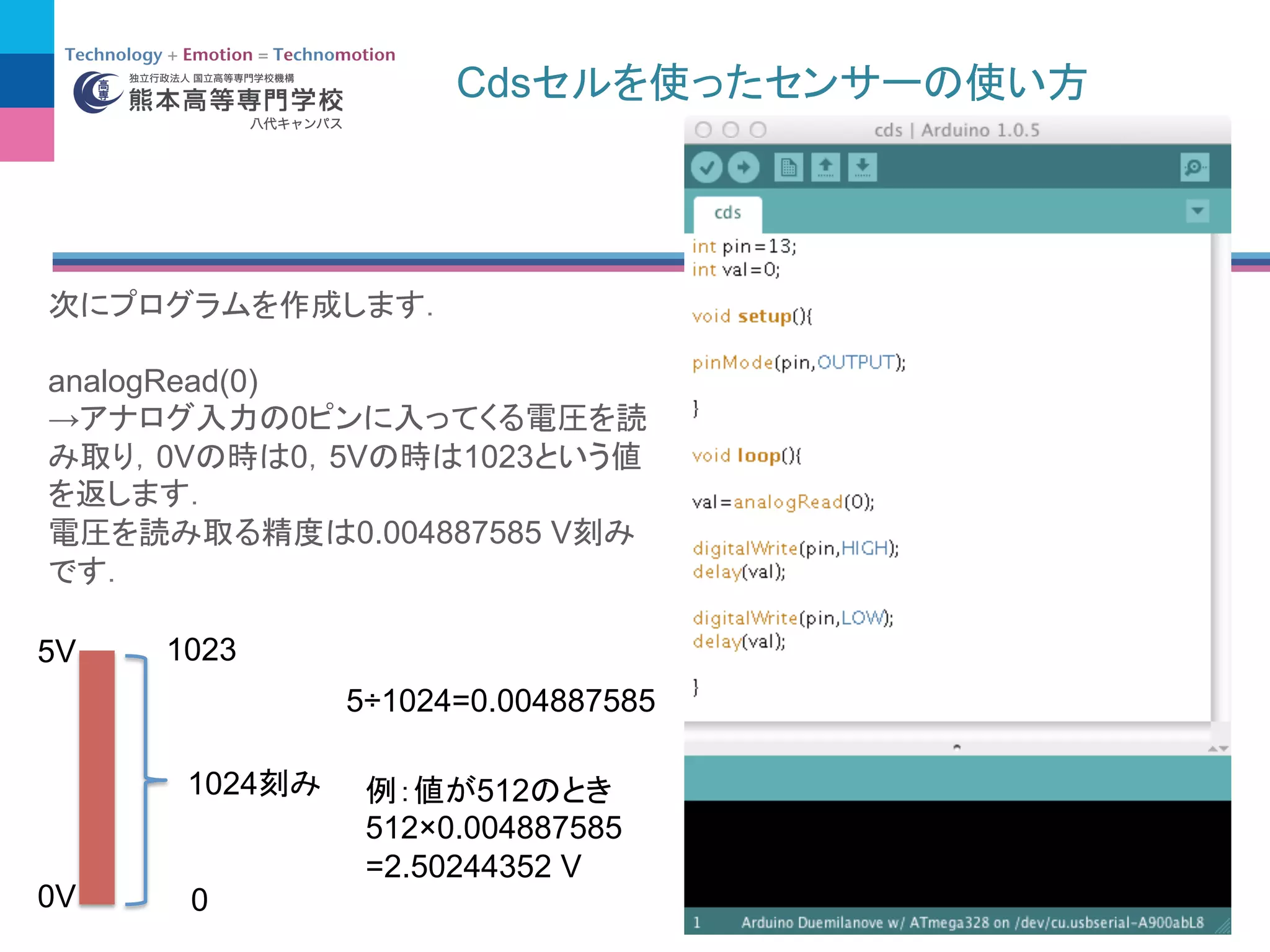


![(4)
analogRead(0)
→ 0
0V 0 5V 1023
0.004887585 V
0V
5V
0
1023
1024
5÷1024=0.004887585
512
512×0.004887585
=2.50244352 V
0 0V
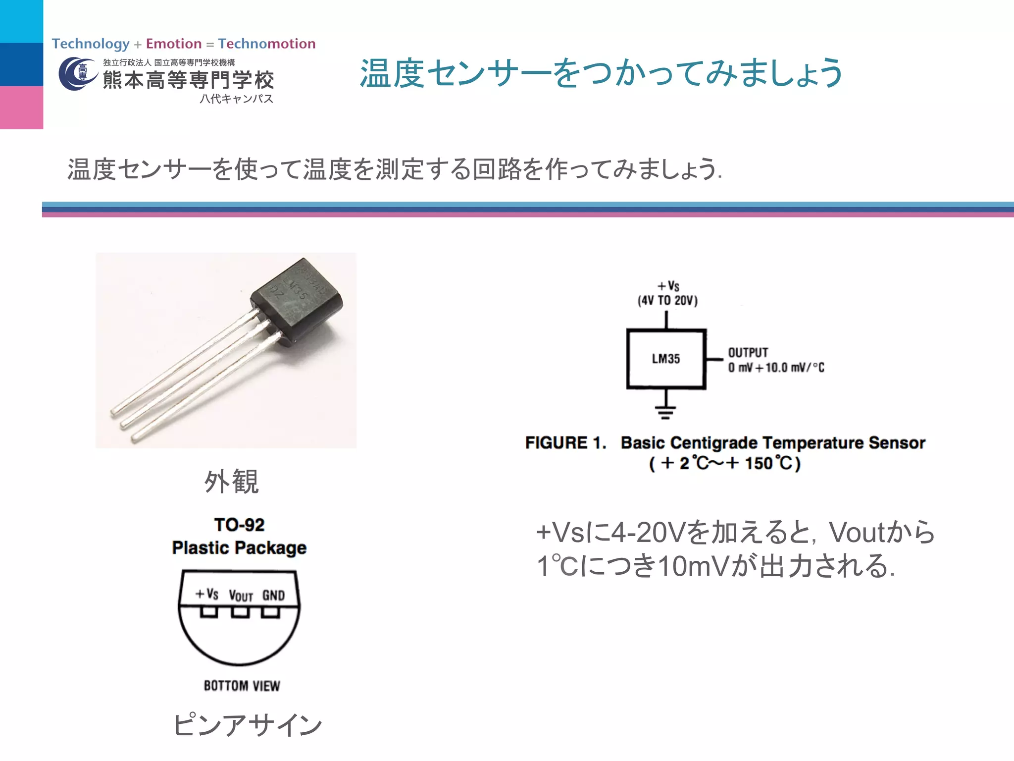
1
10mV(=0.01V)
20 Vout
Vout = 0.01×20 = 0.2 [V]
analogRead()](https://image.slidesharecdn.com/h25-140608215740-phpapp02/75/25-Arduino-60-2048.jpg)
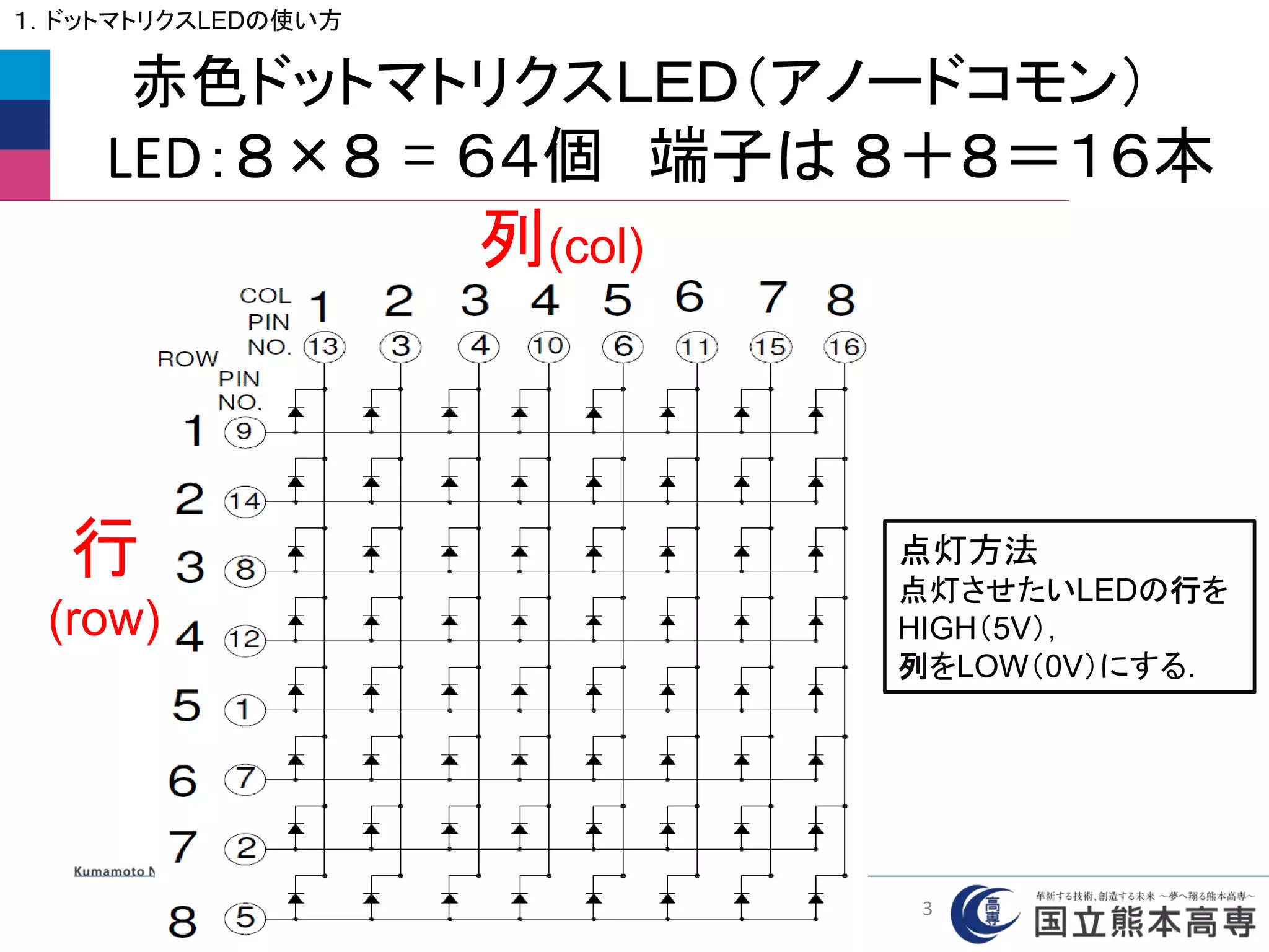
![どれか1つを点灯させる
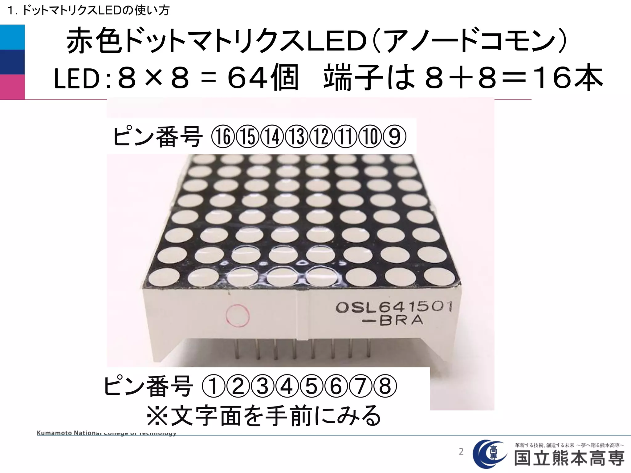
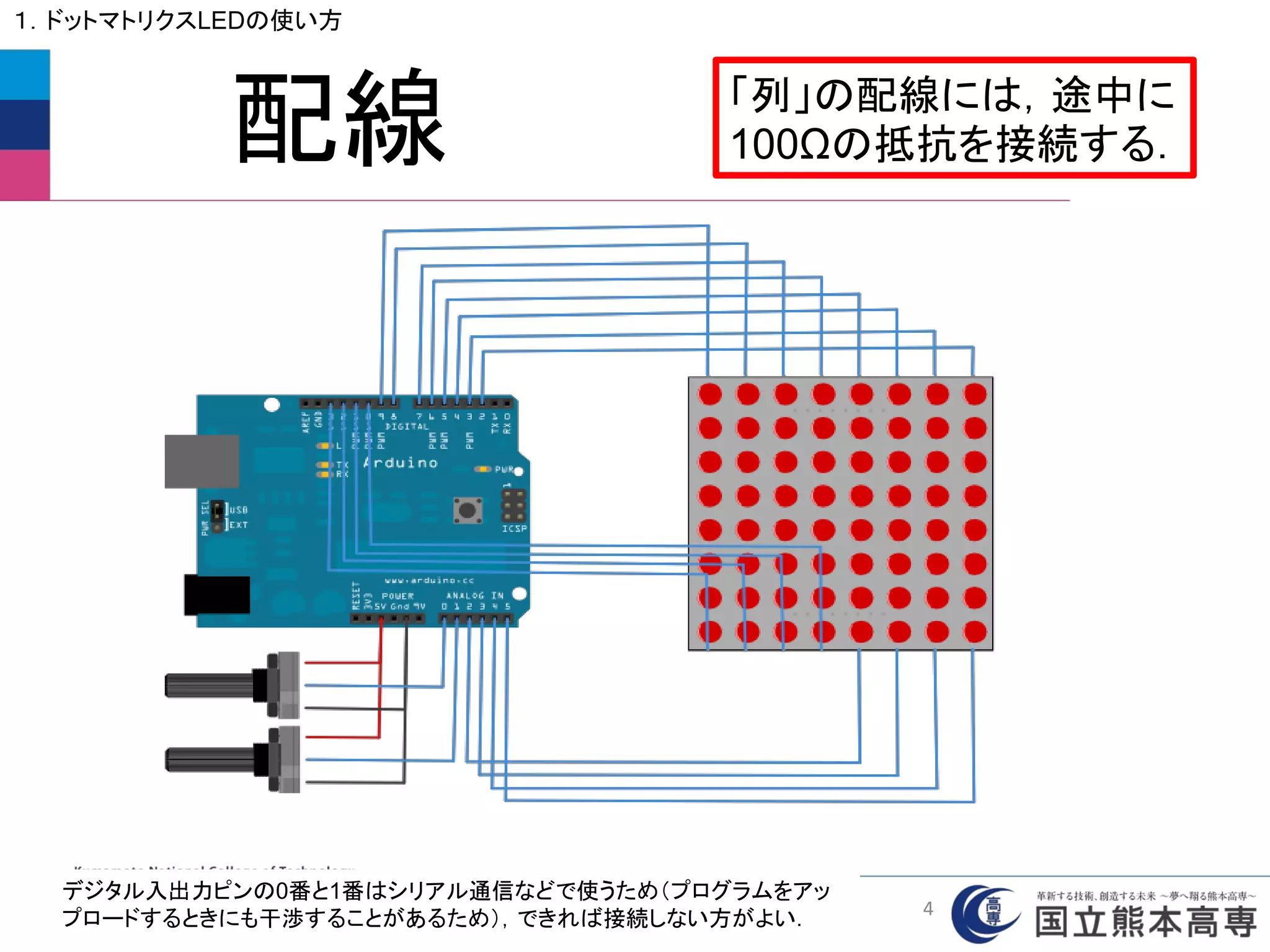
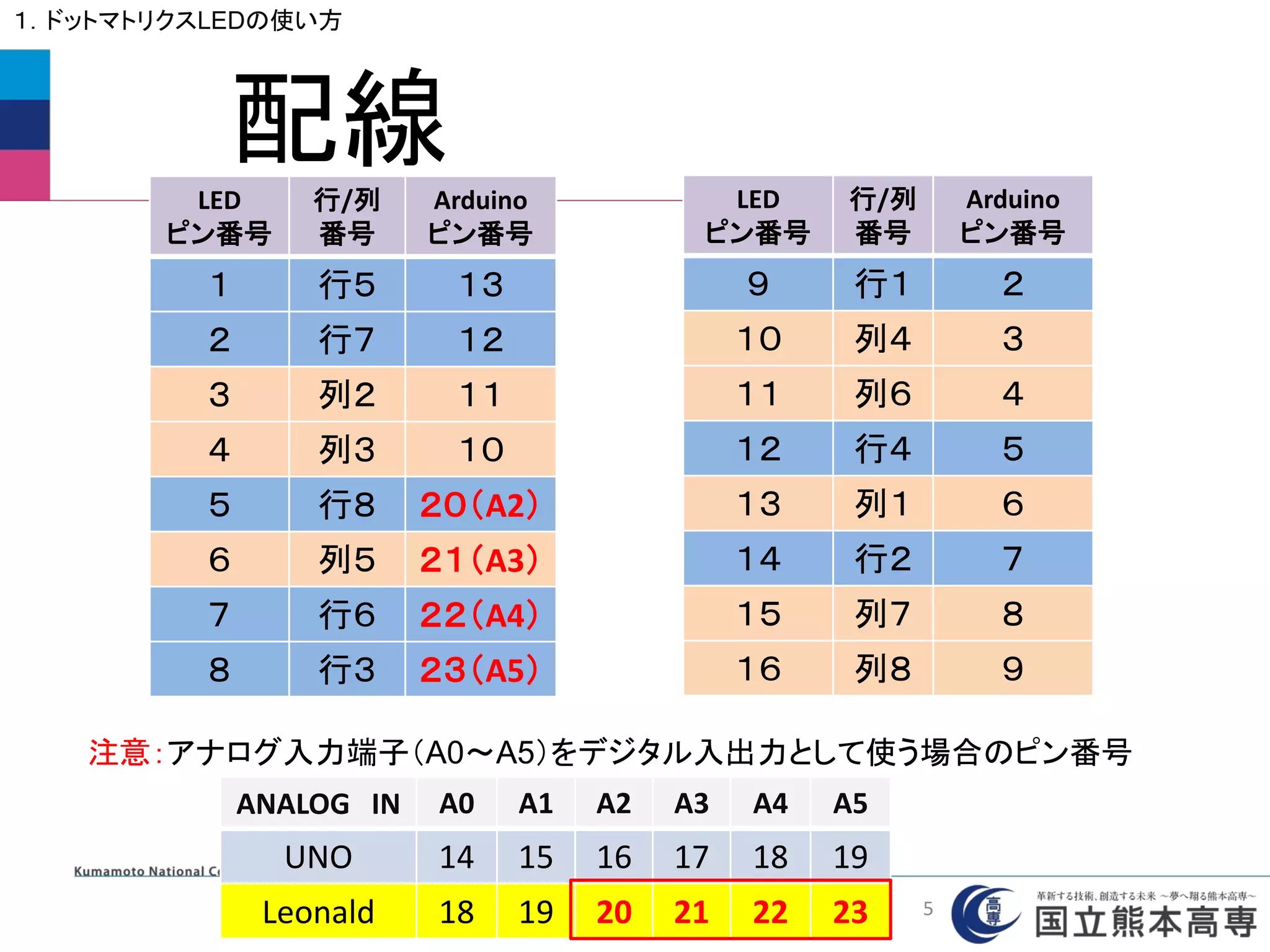
1.ドットマトリクスLEDの使い方
const int row[8] = { 2,7,23,5,13,22,12,20 }; //行のArduinoのピン番号
const int col[8] = { 6,11,10,3,21,4,8,9 }; //列のArduinoのピン番号
void setup(){
for(int i=0; i < 8; i++){ // 8回繰り返し
pinMode(col[i], OUTPUT); // 行の端子を「出力」に設定
pinMode(row[i], OUTPUT); // 列の端子を「出力」に設定
digitalWrite(col[i],HIGH); // 列にHIGHを出力してLEDを消灯
}
} ※この部分はこの後共通して使います
LED_MAT_1
6](https://image.slidesharecdn.com/h25-140608215740-phpapp02/75/25-Arduino-74-2048.jpg)
![どれか1つを点灯させる
1.ドットマトリクスLEDの使い方
void loop(){
digitalWrite(row[0],HIGH); // ある行にHIGH(5V)を出力
digitalWrite(col[0], LOW); // ある列にLOW(0V)を出力
}
※配列の番号を変えて,任意の場所を点灯させてみよう.
ただし,配列の番号(アドレス)は0から始まることに注意!
LED_MAT_1
7](https://image.slidesharecdn.com/h25-140608215740-phpapp02/75/25-Arduino-75-2048.jpg)
![順番に1個ずつ点灯させる
1.ドットマトリクスLEDの使い方
void loop(){
for(int i=0; i < 8; i++){ // 8回繰り返し(行の移動)
digitalWrite(row[i],HIGH); // 行にHIGHを出力⇒点灯準備
for(int j=0; j < 8; j++){ // 8回繰り返し(列の移動)
digitalWrite(col[j], LOW); // 列にLOWを出力 ⇒ LED点灯
delay(500); // 移動の間隔 この場合は0.5秒
digitalWrite(col[j],HIGH); // 列にHIGHを出力 ⇒ LED消灯
}
digitalWrite(row[i],LOW); // 行にLOWを出力⇒点灯準備解除
}
}
64個がすべて点灯して見えるようにdelayMicroseconds( )
に替えて値を変更してみましょう.
LED_MAT_2
8](https://image.slidesharecdn.com/h25-140608215740-phpapp02/75/25-Arduino-76-2048.jpg)
![1個ずつ右にずらしながら点灯させ,すべて点
灯したらその行を消灯して次の行へ移動
void loop(){
for(int i=0; i < 8; i++){
digitalWrite(row[i], HIGH); // 行をHIGHにする(ONの準備)
for(int k=0; k<8; k++){ // 一行すべてONになるまで繰り返し
for(int j=0; j<8-k; j++){ // ONの横移動
digitalWrite(col[j], LOW); // 列をLOWにする(LED ON)
delay(100); // 移動スピード
digitalWrite(col[j],HIGH); // 列をHIGHにする(LED OFF)
}
digitalWrite(col[7-k],LOW); // 最後のLEDをONに保つ
}
for(int j=0; j<8; j++){ // 一行すべてOFFになるまで繰り返し
digitalWrite(col[j], HIGH); // 列をHIGHにする(LED OFF)
}
digitalWrite(row[i],LOW); // 行のLED OFF(その行すべてOFF)
}
}
LED_MAT_3
1.ドットマトリクスLEDの使い方
9](https://image.slidesharecdn.com/h25-140608215740-phpapp02/75/25-Arduino-77-2048.jpg)
![一文字の表示法
2.文字や記号の表示方法
boolean matrix[8][8]={
{0,0,0,1,1,0,0,0},
{0,0,1,0,0,1,0,0},
{0,1,0,0,0,0,1,0},
{0,1,0,0,0,0,1,0},
{0,1,0,0,0,0,1,0},
{0,1,1,1,1,1,1,0},
{0,1,0,0,0,0,1,0},
{0,1,0,0,0,0,1,0}
};
setup( )の前に文字データを二次元配列 matrix[行数][列数]
で準備する.
//boolean型はtrue(1)かfalse(0)だけ
黒を1 ⇒
白を0 ⇒
10](https://image.slidesharecdn.com/h25-140608215740-phpapp02/75/25-Arduino-78-2048.jpg)
![一文字の表示法
2.文字や記号の表示方法
void loop(){
for(int i =0; i < 8; i++){ // 行の繰り返し(配列を縦にみていく)
digitalWrite(row[i],HIGH); // 行をHIGHにする(ONの準備)
for(int j = 0; j < 8; j++){ // 列の繰り返し(配列を横にみていく)
if(matrix[i][j] == 1){ // もし配列の中身が1ならば次の{}を実行
digitalWrite(col[j], LOW); // LED ON(その列をLOWにする)
delayMicroseconds(200); // 点灯時間
}
digitalWrite(col[j],HIGH); // LED OFF(その列をHIGHにする)
}
digitalWrite(row[i],LOW); // 行をLOWにする(その行すべてOFF)
}
}
LED_MAT_CHARACTER1
11](https://image.slidesharecdn.com/h25-140608215740-phpapp02/75/25-Arduino-79-2048.jpg)
![任意の文字や絵の表示
2.文字や記号の表示方法
LED_MAT_CHARACTER2
黒を1⇒
白を0⇒
左側に白黒で文字や絵を描き,右側に 1,0 のデータを作る.
右側の 1,0 のデータをmatrix[8][8]に書いて実行させてみましょう.
12](https://image.slidesharecdn.com/h25-140608215740-phpapp02/75/25-Arduino-80-2048.jpg)
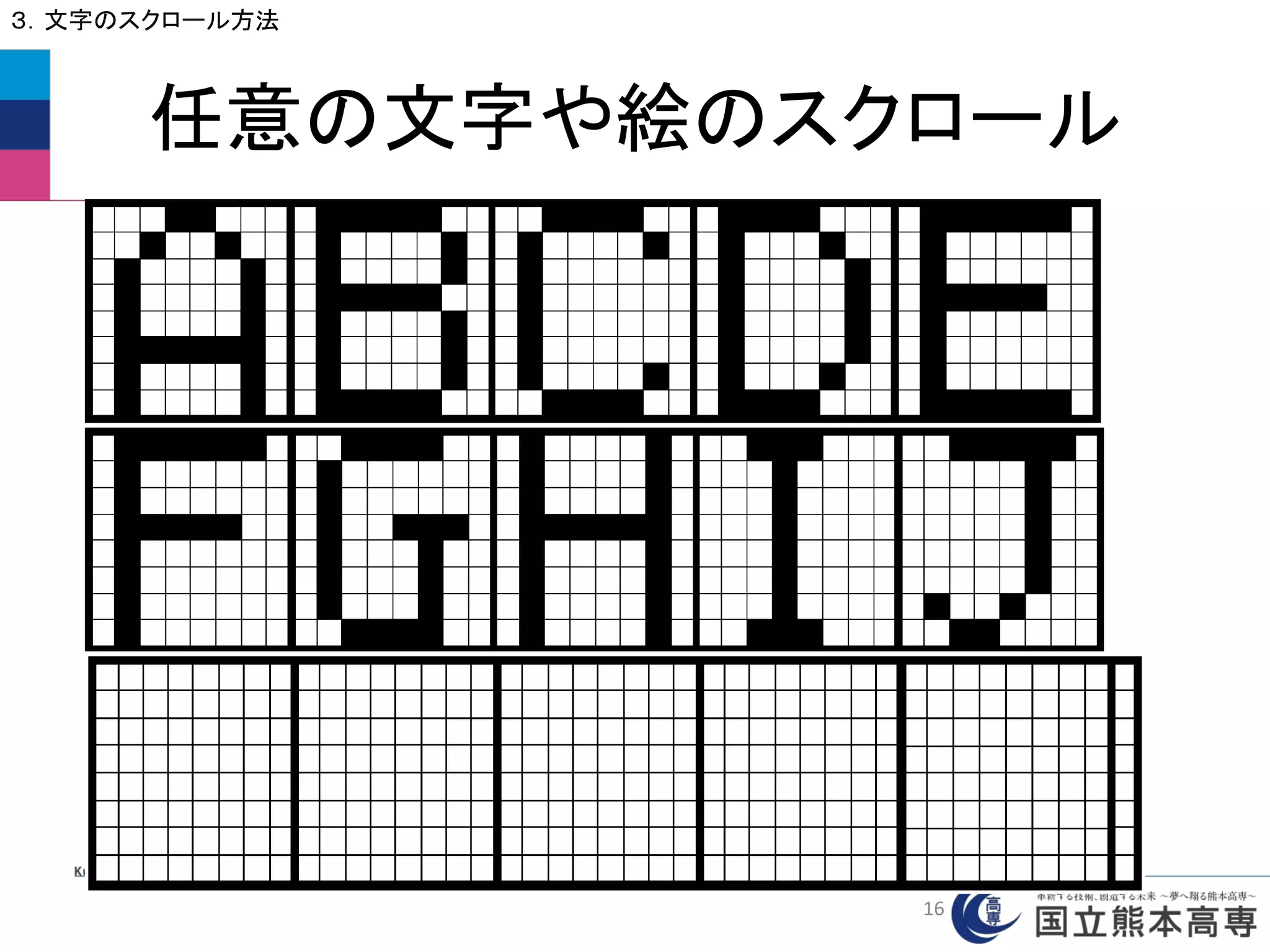
![文字スクロール
3.文字のスクロール方法
boolean matrix[8][MAX_LEN+1]={
{1,0,0,0,0,0,1,0,1,0,0,0,0,0,1,0,1,1,1,1,1,1,1,0,1,1,1,1,1,0,0,0,0},
{0,1,0,0,0,1,0,0,1,0,0,0,0,0,1,0,0,0,0,0,1,0,0,0,0,0,1,0,0,0,0,0,0},
{0,0,1,0,1,0,0,0,1,0,0,0,0,0,1,0,0,0,0,0,1,0,0,0,0,0,1,0,0,0,0,0,0},
{0,0,0,1,0,0,0,0,1,0,0,0,0,0,1,0,0,0,0,0,1,0,0,0,0,0,1,0,0,0,0,0,0},
{0,0,0,1,0,0,0,0,1,0,0,0,0,0,1,0,0,0,0,0,1,0,0,0,0,0,1,0,0,0,0,0,0},
{0,0,0,1,0,0,0,0,1,0,0,0,0,0,1,0,1,0,0,0,1,0,0,0,0,0,1,0,0,0,0,0,0},
{0,0,0,1,0,0,0,0,1,0,0,0,0,0,1,0,1,0,0,0,1,0,0,0,0,0,1,0,0,0,0,0,0},
{0,0,0,1,0,0,0,0,0,1,1,1,1,1,0,0,0,1,1,1,0,0,0,0,1,1,1,1,1,0,0,0,0}
};
// 8行,(8×文字数+1)列の配列を作る.
// 最後の列はすべて0としておく.
空の列
#define MAX_LEN 32 //8×4=32文字 文字数に合わせて変更する
LED_MAT_SCROLL
13](https://image.slidesharecdn.com/h25-140608215740-phpapp02/75/25-Arduino-81-2048.jpg)
![文字スクロール(文字表示)
3.文字のスクロール方法
void loop(){
int count = 20; // 1文字の表示回数 5(早い)~50(ゆっくり)
while(count>0){ // count数だけ繰り返し
for(int i=0; i<8; i++){ // 行の繰り返し(配列を縦にみていく)
digitalWrite(row[i],HIGH); // 行をHIGHにする(ONの準備)
for(int j = 0; j < 8; j++){ // 列の繰り返し(配列を横にみていく)
if(matrix[i][j] ==1 ){ // 配列の中身が1のときだけ次を実行
digitalWrite(col[j], LOW); // LED ON
delayMicroseconds(200); // 点灯時間
}
digitalWrite(col[j],HIGH); // LED OFF
}
digitalWrite(row[i],LOW);
}
count--; // countを1減らす
}
次ページへ続く
LED_MAT_SCROLL
14](https://image.slidesharecdn.com/h25-140608215740-phpapp02/75/25-Arduino-82-2048.jpg)
![文字スクロール(文字の移動)
3.文字のスクロール方法
for(int k = 0; k < 8; k++){ // 行の繰り返し
matrix[k][MAX_LEN] = matrix[k][0]; // 最後の列に1列目を移動
for(int l = 0; l < MAX_LEN; l++){ // 列の繰り返し
matrix[k][l]=matrix[k][l+1]; // 2列目以降を1つ左へずらす
}
}
}
文字データの二次元配列を1列ずらす
LED_MAT_SCROLL
15](https://image.slidesharecdn.com/h25-140608215740-phpapp02/75/25-Arduino-83-2048.jpg)
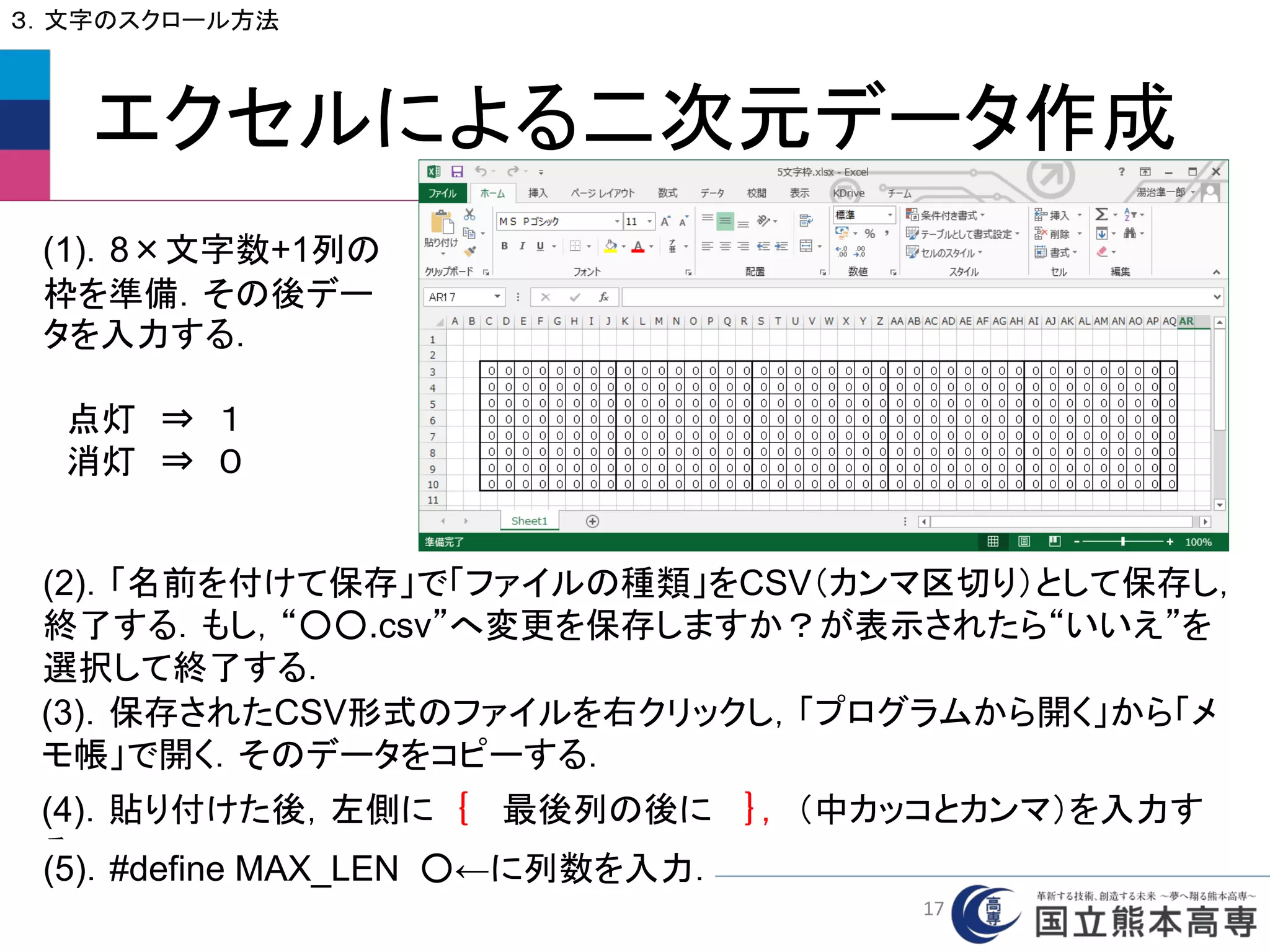
![好きな文字や図案を作って
スクロールさせてみよう
3.文字のスクロール方法
(1) エクセルによる文字や図案の作成
⇒ CSV形式で保存 ⇒ メモ帳で開く
(2) データをboolean matrix[8][MAX_LEN+1]へコピーする.
(3) 配列データの左に 「 { 」,右側に「 },」を追加する.
(3) 文字数(列の数)に合わせて MAX_LEN を変更する.
(4) loop( )内の count でスクロールスピードを調整する.
18](https://image.slidesharecdn.com/h25-140608215740-phpapp02/75/25-Arduino-86-2048.jpg)
![スケッチの例 RowColumnScanning を使用
4.外部入力による点灯位置の制御
(1) ファイル ⇒ スケッチの例 ⇒ 07.Display ⇒
RowColumnScanning を選択
(2) Arduino UNO のピン番号をLEONALD仕様に変更
// 2-dimensional array of row pin numbers:
const int row[8] = {2,7,19,5,13,18,12,16 } を
const int row[8] = {2,7,23,5,13,22,12,20 } に変更
// 2-dimensional array of column pin numbers:
const int col[8] = {6,11,10,3,17,4,8,9 } を
const int col[8] = {6,11,10,3,21,4,8,9 } に変更
21](https://image.slidesharecdn.com/h25-140608215740-phpapp02/75/25-Arduino-89-2048.jpg)
![RowColumnScanning
4.外部入力による点灯位置の制御
// 2-dimensional array of pixels:
int pixels[8][8]; // ドットマトリクスLED用の
8×8の二次元配列を準備
// cursor position:
int x = 5; //LEDのx軸(行方向)の位置を決める変数 ⇒ pixelsのx番地
int y = 5; //LEDのy軸(列方向)の位置を決める変数 ⇒ pixelsのy番地
// initialize the pixel matrix:
for (int x = 0; x < 8; x++) {
for (int y = 0; y < 8; y++) {
pixels[x][y] = HIGH; //配列pixelsの中身をすべてHIGHに初期化
}
}
void setup( )は省略
0
1
2
3
4
5
6
7
yの番地
xの番地
0 1 2 3 4 5 6 7
22](https://image.slidesharecdn.com/h25-140608215740-phpapp02/75/25-Arduino-90-2048.jpg)
![void readSensors() {
// turn off the last position:
pixels[x][y] = HIGH; // 配列pixelsの番地(x,y:前の番地)の中身をHIGHに設定
// read the sensors for X and Y values:
x = 7 - map(analogRead(A0), 0, 1023, 0, 7); //入力電圧を0~7へ変換し,
それを7から引いたものをx
y = map(analogRead(A1), 0, 1023, 0, 7); //入力電圧を0~7へ変換し,それをy
// set the new pixel position low so that the LED will turn on
// in the next screen refresh:
pixels[x][y] = LOW; // 配列pixelsの番地(x,y:現在の番地)の中身をLOWに設定
}
RowColumnScanning
4.外部入力による点灯位置の制御
A0の電圧を取得 現在の範囲 新しい範囲
0
1
2
3
4
5
6
7
yの番地
xの番地
0 1 2 3 4 5 6 7
readSensors()は,可変抵抗のつまみの位置を
電圧として読み込み,その値によって点灯位置の番
地x,y を決め,そこがONになるように配列pixelsに
LOWをセットする.
23](https://image.slidesharecdn.com/h25-140608215740-phpapp02/75/25-Arduino-91-2048.jpg)
![RowColumnScanning
4.外部入力による点灯位置の制御
void refreshScreen() { //pixel[x][y]をスキャンしてLOWの位置でLEDを点灯させ,すぐに消す
// iterate over the rows (anodes):
for (int thisRow = 0; thisRow < 8; thisRow++) { // 行の繰り返し
// take the row pin (anode) high:
digitalWrite(row[thisRow], HIGH); // thisRow番目の行をHIGHにする(ONの準備)
// iterate over the cols (cathodes):
for (int thisCol = 0; thisCol < 8; thisCol++) { // 列の繰り返し
// get the state of the current pixel;
int thisPixel = pixels[thisRow][thisCol]; // thisPixel に 現在のpixels[thisRow][thisCol] の中身を代入
// when the row is HIGH and the col is LOW,
// the LED where they meet turns on:
digitalWrite(col[thisCol], thisPixel); // thisCol列 に thisPixel の値をデジタル出力
(thisPixel が LOW のところだけ LED ON)
// turn the pixel off:
if (thisPixel == LOW) { // もし thisPixel の中身が LOW ならば次を実行
digitalWrite(col[thisCol], HIGH); // thisCol列に HIGH を出力(LED OFF)
}
}
// take the row pin low to turn off the whole row:
digitalWrite(row[thisRow], LOW); // thisRow番目の行をLOWにする(OFFに戻す)
}
}
点灯
消灯
24](https://image.slidesharecdn.com/h25-140608215740-phpapp02/75/25-Arduino-92-2048.jpg)