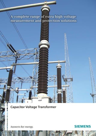
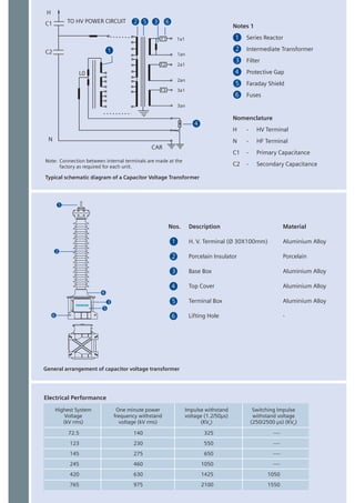
Answers for energy.
Capacitor Voltage Transformer
Siemens Capacitor Voltage Transformers are based on
technology from Trench, a recognized world leader in
the design and manufacture of high voltage
equipment for application on electric utility and high
energy industrial systems.
Capacitor Voltage Transformers convert transmission
class voltages to standardized low and easily
measurable values, which are used for metering,
protection and control of the high voltage system. As
such, the need for accurate and reliable voltage
transformation is essential. Additionally, Capacitor
Voltage Transformers serve as coupling capacitors for
coupling high frequency power line carrier signals to
the transmission line.
Capacitor Voltage Transformer
Today, Siemens is a world-wide leader with an entire
range of instrument transformers from 72.5 kV to
800 kV covering:
Current Transformers
Capacitor Voltage Transformers
Voltage (Potential) Transformers
Combined Units (Combined Current & Voltage
Transformers)
n
n
n
n
The Siemens factory in Aurangabad fulfils the
demand of our customers for highly reliable Capacitor
Voltage Transformers.
•
(other Standards on request)
• Applications from 72.5 kV–800 kV
• Quality Assurance in accordance with ISO 9001
• Capable of carrier coupling PLC signals to the
network
• Optimized insulation system design utilizing state-
of-the-art processing techniques with mineral oil &
synthetic insulating fluids
• Stability of capacitance and accuracy over a long
period of time due to superior clamping system
design
Meets all IEC and IS metering and protection classes
Features
• Oil expansion by way of hermetically sealed
stainless steel bellows assures the integrity of the
insulation system over time
• Maintenance-free oil filled cast aluminum base box
• Superior transient response characteristics
• Passive ferro-resonance suppression circuit provides
superior damping while not degrading transient
response
• Potential grounding switch to measure capacitance
and tan delta
Construction
Siemens CVT's consist of two primary assemblies; the
high voltage capacitor sections and the base box,
housing the electro-magnetic components.
Series connected capacitor elements, housed in
porcelain shells, each hermetically sealed, are
referred to as capacitor sections. The dielectric of the
capacitor elements is made up of high quality
polypropylene film/paper and impregnated with
highly processed synthetic fluid. Each capacitor
section is equipped with a stainless steel bellow
which will allow the synthetic fluid to expand and
contract with changes in ambient operating
temperature while maintaining the hermetic sealing.
It is over these capacitor sections that most of the
high voltage will be dropped.
A tap voltage (approximately 5-12 kV depending on
type) is taken from the lowest capacitor section and
fed to an electromagnetic circuit in the cast
aluminum base box. The base box contains the
intermediate transformer which will provide the final
output voltages via multiple tapped secondary
windings, series compensating reactor and ferro-
resonance control circuitry. The base box is filled with
dried mineral oil, protecting the components from
environmental deterioration.
Ferro-resonance is simply and effectively controlled
by utilization of low flux density designed magnetic
circuitry and a saturable reactor controlled damping
circuit connected across the secondary winding. The
ferro-resonance suppression circuit does not
adversely affect transient response.
Note: Connection between internal terminals are made
factory as required for each unit.
at the
Typical schematic diagram Capacitor Voltage Transformerof a
Notes 1
Series Reactor
Intermediate Transformer
Filter
Protective Gap
Faraday Shield
Fuses
Nomenclature
H - HV Terminal
N - HF Terminal
C1 - Primary Capacitance
C2 - Secondary Capacitance
1
2
6
4
3
5
1
2
3
4
5
6
1
2
3
4
5
6
Nos. Description Material
H. V. Terminal (Ø 30X100mm)
Porcelain Insulator Porcelain
Base Box Alloy
Top Cover Alloy
Terminal Box Alloy
Lifting Hole -
Aluminium Alloy
Aluminium
Aluminium
Aluminium
General arrangement of capacitor voltage transformer
1an
1a1
2a1
2an
3a1
3an
2 5 3 6
H
C1
C2
TO HV POWER CIRCUIT
F1
F2
F3
L0
1
4
N
CAR
Electrical Performance
Highest System
Voltage
(kV rms)
One minute power
frequency withstand
voltage (kV rms)
Impulse withstand
voltage (1.2/50µs)
(KV )p
Switching Impulse
withstand voltage
(250/2500 µs) (KV )p
72.5
123
145
245
420
765
140
230
275
460
630
975
325
550
650
1050
1425
2100
----
----
----
----
1050
1550
“Product development is a continuous process. Consequently the data indicated in this
leaflet is subject to change without prior notice. For latest issue contact our Sales Office.”
Siemens Ltd.
Energy Sector - Energy Transmission
Aurangabad Works:
E76 – MIDC Waluj,
Aurangabad, India. 431 136
Tel: +91 240 2565 191
Fax: +91 240 2554 701
Order No.: PTD-03-152-042
For more information, please contact:
Western Region:
Mumbai office:
Thane Belapur Road,
Thane - 400 601
Tel.: (022) 2762 3990
Fax: (022) 2762 8002
Vadodara office:
Ohm Business Park
Ellora Park, Subhanpura
Vadodara - 390 023
Tel.: 0265-6692 100
Fax: 0265-6692 190
Eastern Region:
Kolkata office:
43, Shanti Palli
Rasbihari Bypass Connector
Kolkata - 700 042
Tel.: (033) 2444 9302
Fax: (033) 2444 9012
Northern Region:
Delhi office:
Plot No. 6-A, Sector 18
Maruti Industrial Area
HUDA, Gurgaon - 122 015
Tel.: (0124) 284 6000
Fax: (0124) 284 6061
Southern Region:
Chennai office:
144, Mahatma Gandhi Road
P. O. Box No. 3323
Chennai - 600 034
Tel.: (044) 2833 4144
Fax: (044) 2833 4450

Instrument transformer __cvt_transformer

  • 1.
    Answers for energy. CapacitorVoltage Transformer
  • 2.
    Siemens Capacitor VoltageTransformers are based on technology from Trench, a recognized world leader in the design and manufacture of high voltage equipment for application on electric utility and high energy industrial systems. Capacitor Voltage Transformers convert transmission class voltages to standardized low and easily measurable values, which are used for metering, protection and control of the high voltage system. As such, the need for accurate and reliable voltage transformation is essential. Additionally, Capacitor Voltage Transformers serve as coupling capacitors for coupling high frequency power line carrier signals to the transmission line. Capacitor Voltage Transformer Today, Siemens is a world-wide leader with an entire range of instrument transformers from 72.5 kV to 800 kV covering: Current Transformers Capacitor Voltage Transformers Voltage (Potential) Transformers Combined Units (Combined Current & Voltage Transformers) n n n n The Siemens factory in Aurangabad fulfils the demand of our customers for highly reliable Capacitor Voltage Transformers.
  • 3.
    • (other Standards onrequest) • Applications from 72.5 kV–800 kV • Quality Assurance in accordance with ISO 9001 • Capable of carrier coupling PLC signals to the network • Optimized insulation system design utilizing state- of-the-art processing techniques with mineral oil & synthetic insulating fluids • Stability of capacitance and accuracy over a long period of time due to superior clamping system design Meets all IEC and IS metering and protection classes Features • Oil expansion by way of hermetically sealed stainless steel bellows assures the integrity of the insulation system over time • Maintenance-free oil filled cast aluminum base box • Superior transient response characteristics • Passive ferro-resonance suppression circuit provides superior damping while not degrading transient response • Potential grounding switch to measure capacitance and tan delta
  • 4.
    Construction Siemens CVT's consistof two primary assemblies; the high voltage capacitor sections and the base box, housing the electro-magnetic components. Series connected capacitor elements, housed in porcelain shells, each hermetically sealed, are referred to as capacitor sections. The dielectric of the capacitor elements is made up of high quality polypropylene film/paper and impregnated with highly processed synthetic fluid. Each capacitor section is equipped with a stainless steel bellow which will allow the synthetic fluid to expand and contract with changes in ambient operating temperature while maintaining the hermetic sealing. It is over these capacitor sections that most of the high voltage will be dropped. A tap voltage (approximately 5-12 kV depending on type) is taken from the lowest capacitor section and fed to an electromagnetic circuit in the cast aluminum base box. The base box contains the intermediate transformer which will provide the final output voltages via multiple tapped secondary windings, series compensating reactor and ferro- resonance control circuitry. The base box is filled with dried mineral oil, protecting the components from environmental deterioration. Ferro-resonance is simply and effectively controlled by utilization of low flux density designed magnetic circuitry and a saturable reactor controlled damping circuit connected across the secondary winding. The ferro-resonance suppression circuit does not adversely affect transient response.
  • 5.
    Note: Connection betweeninternal terminals are made factory as required for each unit. at the Typical schematic diagram Capacitor Voltage Transformerof a Notes 1 Series Reactor Intermediate Transformer Filter Protective Gap Faraday Shield Fuses Nomenclature H - HV Terminal N - HF Terminal C1 - Primary Capacitance C2 - Secondary Capacitance 1 2 6 4 3 5 1 2 3 4 5 6 1 2 3 4 5 6 Nos. Description Material H. V. Terminal (Ø 30X100mm) Porcelain Insulator Porcelain Base Box Alloy Top Cover Alloy Terminal Box Alloy Lifting Hole - Aluminium Alloy Aluminium Aluminium Aluminium General arrangement of capacitor voltage transformer 1an 1a1 2a1 2an 3a1 3an 2 5 3 6 H C1 C2 TO HV POWER CIRCUIT F1 F2 F3 L0 1 4 N CAR Electrical Performance Highest System Voltage (kV rms) One minute power frequency withstand voltage (kV rms) Impulse withstand voltage (1.2/50µs) (KV )p Switching Impulse withstand voltage (250/2500 µs) (KV )p 72.5 123 145 245 420 765 140 230 275 460 630 975 325 550 650 1050 1425 2100 ---- ---- ---- ---- 1050 1550
  • 6.
    “Product development isa continuous process. Consequently the data indicated in this leaflet is subject to change without prior notice. For latest issue contact our Sales Office.” Siemens Ltd. Energy Sector - Energy Transmission Aurangabad Works: E76 – MIDC Waluj, Aurangabad, India. 431 136 Tel: +91 240 2565 191 Fax: +91 240 2554 701 Order No.: PTD-03-152-042 For more information, please contact: Western Region: Mumbai office: Thane Belapur Road, Thane - 400 601 Tel.: (022) 2762 3990 Fax: (022) 2762 8002 Vadodara office: Ohm Business Park Ellora Park, Subhanpura Vadodara - 390 023 Tel.: 0265-6692 100 Fax: 0265-6692 190 Eastern Region: Kolkata office: 43, Shanti Palli Rasbihari Bypass Connector Kolkata - 700 042 Tel.: (033) 2444 9302 Fax: (033) 2444 9012 Northern Region: Delhi office: Plot No. 6-A, Sector 18 Maruti Industrial Area HUDA, Gurgaon - 122 015 Tel.: (0124) 284 6000 Fax: (0124) 284 6061 Southern Region: Chennai office: 144, Mahatma Gandhi Road P. O. Box No. 3323 Chennai - 600 034 Tel.: (044) 2833 4144 Fax: (044) 2833 4450