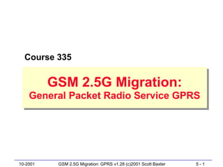
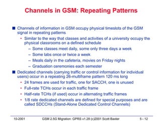
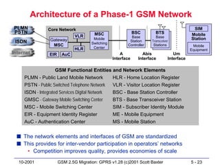
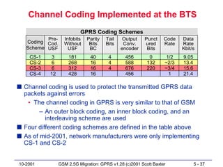
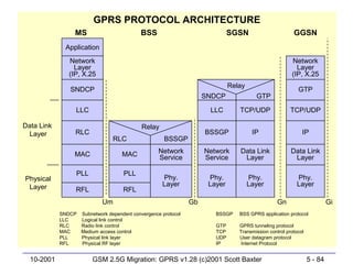
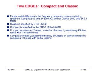
GSM is the most widely used mobile technology globally, with over 500 million users. However, it has limited data capabilities. GPRS provides a packet-switched way to access GSM networks for both interim and long-term packet data access. GPRS was defined in 1996 and began wide deployment in 2001, providing both voice and higher speed packet data access over GSM networks as an interim solution until 3G networks like UMTS are more widely available.


![PDP Context Activation Procedure
MS SGSN GGSN
Activate PDP context request
[PDP type, PDP address,
QoS requested, access point…]
Security functions
Create PDP context request
[PDP type, PDP address,
QoS requested, access point…]
Create PDP context response
Activate PDP context accept [PDP type, QoS negotiated…]
[PDP type, PDP address,
QoS negotiated…]
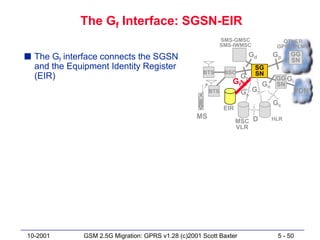
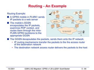
s The mobile station requests a PDP context from the SGSN
• If dynamic PDP address assignment is requested, the parameter PDP
address will be left empty
s Security functions (authentication) will be performed
s SGSN will ask for a PDP context from the GGSN
s The GGSN will create a new entry in its PDP context table
s GGSN sends confirmation to the SGSN including address if dynamic
s SGSN updates its PDP context table and confirms to the mobile
10-2001 GSM 2.5G Migration: GPRS v1.28 (c)2001 Scott Baxter 5 - 62](https://image.slidesharecdn.com/335-12738727801983-phpapp01/85/GSM-2-5G-Migration-62-320.jpg)
![Anonymous PDP Context Activation
MS SGSN GGSN
Activate PDP context request
[PDP type, PDP address,
QoS requested, access point…]
Security functions
Create PDP context request
[PDP type, PDP address,
QoS requested, access point…]
Create PDP context response
Activate PDP context accept [PDP type, QoS negotiated…]
[PDP type, PDP address,
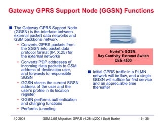
QoS negotiated…]
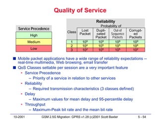
s GPRS also supports anonymous PDP context activation
• In this case, security functions are skipped
• The user (IMSI) using the PDP context is not known to the
network
s Anonymous context activation can be used for prepaid services,
where the user does not want to be identified
• Only dynamic address allocation is possible in this case
10-2001 GSM 2.5G Migration: GPRS v1.28 (c)2001 Scott Baxter 5 - 63](https://image.slidesharecdn.com/335-12738727801983-phpapp01/85/GSM-2-5G-Migration-63-320.jpg)


![Intra-SGSN Routing Area Updates
MS BSS SGSN
Routing area update request Routing area update request
[Old RAI, old P-TMSI signature, [Old RAI, old P-TMSI signature,
Update type] Update type, CI]
Security functions
Routing area update accept
[P-TMSI, PTMSI signature)
Routing area update complete
[P-TMSI] (optional)
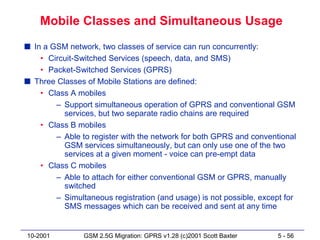
s The mobile has moved into an RA that is assigned to the same
SGSN as the old RA
• The SGSN already has the necessary user profile
• SGSN can assign a new packet temporary mobile subscriber
identity (P-TMSI)
s Since the routing context does not change, there is no need to
inform other network elements, such as the GGSN or the HLR
10-2001 GSM 2.5G Migration: GPRS v1.28 (c)2001 Scott Baxter 5 - 69](https://image.slidesharecdn.com/335-12738727801983-phpapp01/85/GSM-2-5G-Migration-69-320.jpg)
![Inter-SGSN Routing Area Updates
MS BSS SGSN
Routing area update request Routing area update request
[Old RAI, old P-TMSI signature, [Old RAI, old P-TMSI signature,
Update type] Update type, CI]
Security functions
Routing area update accept
[P-TMSI, PTMSI signature)
Routing area update complete
[P-TMSI] (optional)
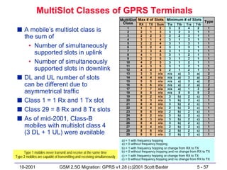
s The new RA is administered by a different SGSN than the old RA
s The new SGSN realizes that the MS has changed to its area and
requests the old SGSN to send the PDP contexts of the user
s The new SGSN informs the involved GGSNs of the users new
routing context
s The HLR (and if needed, the MSC/VLR) are informed about the
user’s new SGSN
10-2001 GSM 2.5G Migration: GPRS v1.28 (c)2001 Scott Baxter 5 - 70](https://image.slidesharecdn.com/335-12738727801983-phpapp01/85/GSM-2-5G-Migration-70-320.jpg)


![EDGE Modulations
Scheme Modulation Maximum Code Rate Family
rate [kb/s]
M CS-9 8PSK 59.2 1.0 A
M CS-8 54.4 0.92 A
M CS-7 44.8 0.76 B
M CS-6 29.6 / 27.2 0.49 A
M CS-5 22.4 0.37 B
M CS-4 GM SK 17.6 1.0 C
M CS-3 14.8 / 13.6 0.80 A
M CS-2 11.2 0.66 B
M CS-1 8.8 0.53 C
10-2001 GSM 2.5G Migration: GPRS v1.28 (c)2001 Scott Baxter 5 - 106](https://image.slidesharecdn.com/335-12738727801983-phpapp01/85/GSM-2-5G-Migration-106-320.jpg)
![The EDGE Multi-Mode Radio Link
Scheme Modulation Maximum Code Rate Header Code Blocks Family
rate [kb/s] Rate per 20 ms
M CS-9 8PSK 59.2 1.0 0.36 2 A
M CS-8 54.4 0.92 0.36 2 A
M CS-7 44.8 0.76 0.36 2 B
M CS-6 29.6 / 27.2 0.49 1/3 1 A
M CS-5 22.4 0.37 1/3 1 B
M CS-4 GM SK 17.6 1.0 0.53 1 C
M CS-3 14.8 / 13.6 0.80 0.53 1 A
M CS-2 11.2 0.66 0.53 1 B
M CS-1 8.8 0.53 0.53 1 C
10-2001 GSM 2.5G Migration: GPRS v1.28 (c)2001 Scott Baxter 5 - 107](https://image.slidesharecdn.com/335-12738727801983-phpapp01/85/GSM-2-5G-Migration-107-320.jpg)


![C04 wireless telecommunication-systems[1]](https://cdn.slidesharecdn.com/ss_thumbnails/c04-wirelesstelecommunicationsystems1-130417045952-phpapp02-thumbnail.jpg?width=640&height=640&fit=bounds)


