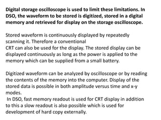
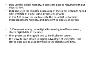
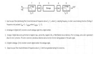
1. A digital storage oscilloscope converts analog signals to digital signals using an analog-to-digital converter and stores the digital data in memory.
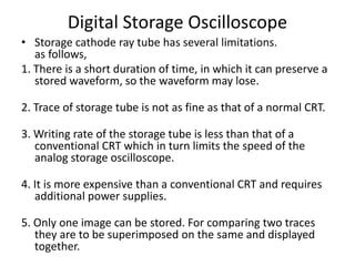
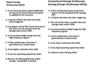
2. It can store waveforms indefinitely, has a higher resolution than analog storage oscilloscopes, and allows for complex digital signal processing.
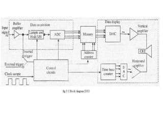
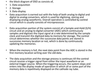
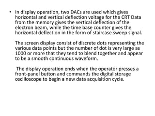
3. The key components are the analog-to-digital converter for digitization, memory for storage, and a digital-to-analog converter along with a CRT for display.