Downloaded 108 times

![Project Report 2017-2018 Synchronizing Panel
KMCT Polytechnic College, Kozhikode Page|2 Dept. of Electrical & Electronics Engg.
2. HISTORY OF ELECTRICITY
Electricity is the set of physical phenomena associated with the presence and motion
of electric charge. Although initially considered a phenomenon separate from magnetism,
since the development of Maxwell's equations, both are recognized as part of a single
phenomenon: electromagnetism. Various common phenomena are related to electricity,
including lightning, static electricity, electric heating, electric discharges and many
others.
The presence of an electric charge, which can be either positive or negative, produces
an electric field. The movement of electric charges is an electric current and produces a
magnetic field.
Electricity is at the heart of many modern technologies, being used for:
Electric power where electric current is used to energize equipment;
Electronics which deals with electrical circuits that involve active electrical
components such as vacuum tubes, transistors, diodes and integrated circuits, and
associated passive interconnection technologies.
Long before any knowledge of electricity existed, people were aware of shocks from
electric fish. Ancient Egyptian texts dating from 2750 BCE referred to these fish as the
"Thunderer of the Nile", and described them as the "protectors" of all other fish. Electric
fish were again reported millennia later by ancient Greek, Roman and Arabic naturalists
and physicians.[2]
Several ancient writers, such as Pliny the Elder and Scribonius Largus,
attested to the numbing effect of electric shocks delivered by catfish and electric rays,
and knew that such shocks could travel along conducting objects.
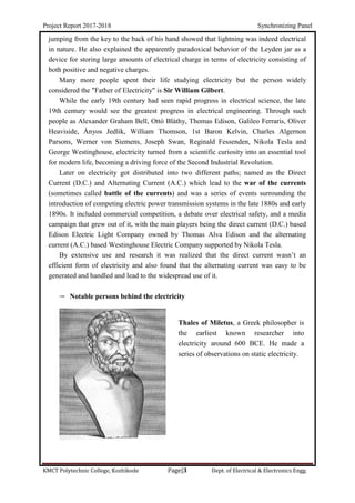
Ancient cultures around the Mediterranean knew that certain objects, such as rods of
amber, could be rubbed with cat's fur to attract light objects like feathers. Thales of
Miletus made a series of observations on static electricity around 600 BCE, from which
he believed that friction rendered amber magnetic, in contrast to minerals such as
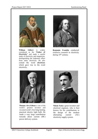
magnetite, which needed no rubbing. Electricity would remain little more than an
intellectual curiosity for millennia until 1600, when the English scientist William Gilbert
made a careful study of electricity and magnetism, distinguishing the lodestone effect
from static electricity produced by rubbing amber. He coined the New Latin word
electricus to refer to the property of attracting small objects after being rubbed. This
association gave rise to the English words "electric" and "electricity", which made their
first appearance in print in Thomas Browne's Pseudodoxia Epidemica of 1646.
Further work was conducted by Otto von Guericke, Robert Boyle, Stephen Gray and
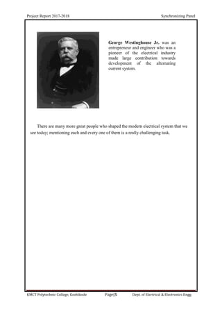
C. F. du Fay. In the 18th century, Benjamin Franklin conducted extensive research in
electricity. In June 1752 he is reputed to have attached a metal key to the bottom of a
dampened kite string and flown the kite in a storm-threatened sky. A succession of sparks](https://image.slidesharecdn.com/synchronizingpanel-191107142554/85/Alternator-AC-Generator-Synchronizing-Panel-8-320.jpg)

The project report by Aswin K. P. on 'synchronizing panels' outlines the importance of synchronizing electrical generators with the power system to prevent damage due to improper connections. It details the synchronization process, techniques, and the significance of alternators and prime movers in electricity generation. Acknowledgments and the project structure are also included, highlighting the project's role in fulfilling diploma requirements at KMCT Polytechnic College.


