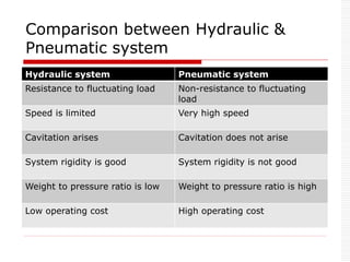
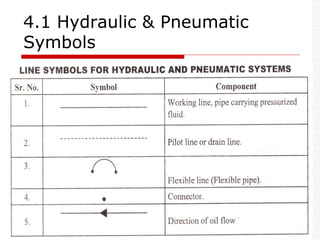
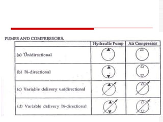
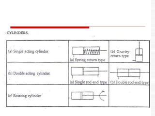
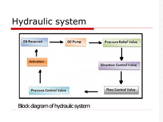
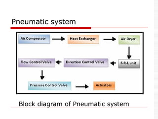
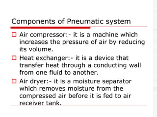
This document describes the basic components of hydraulic and pneumatic systems. It discusses the key components of hydraulic systems which include an oil reservoir, oil pump, pressure relief valve, directional control valve, flow control valve, pressure control valve, and actuators. For pneumatic systems, it outlines the main components as an air compressor, heat exchanger, air dryer, and FRL (filter, regulator, lubricator) unit. It then compares the characteristics of hydraulic and pneumatic systems and provides examples of hydraulic and pneumatic symbols and different types of rotary actuators, valves, and motors used in these systems.
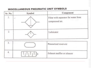
![ F-R-L unit :-
[ Filter, Regulator, Lubricator]
Air filter- it separates solid contaminants
from compressed air and it supplies
clean air to pneumatic system.
Air regulator- it maintains constant
pressure in the system.
Air lubricator- it reduces friction
between internal moving parts of the
system](https://image.slidesharecdn.com/chapter4hydraulic-240211140147-4bbaf8fa/85/Chapter_4_HYDRAULIC-final-ppt-presentation-7-320.jpg)