ARC ONE
arcone.mechbuilders@gmail.com
Fire
Introduction &Basic Design of AFSS
Protection
System
https://www.facebook.com/ArcOneEngineeringServices
0966-5388922 / 0938-3534138
Presented By:
Mechanical & Electrical Engineering Services
2.
Training Rules
Please beconsiderate, take control of your
own noise. Sit in a quiet area
Speak clearly, don’t be afraid to ask if
people can hear you well.
Raise your hand, questions are entertained
anytime
Feel free to contribute your experience
3.
Terminology and References
Refresher
01
02
03
Training
Course
Topics
Day2
Occupancy Hazard Fire Control Approach
Storage Design Approach
Special Occupancy Design Approach
Design Approach
Determining the Design Area
Using the Density Area Curve
Number of Sprinklers to Calculate
Protection Area of Coverage
Walkthrough of Hydraulic Calculations
Fire Pump Selection
Tank Sizing
Hydraulic Calculation
Types of Hazards or Occupancies and Commodities
Terminology
Acceptable to
the authority
having
jurisdiction.
Approved
Theorganization,
office, or individual
responsible for
approving
equipment,
materials, an
installation, or a
procedure.
Authority Having
Jurisdiction
(AHJ)
Equipment,materials
, or services
included in a list
published by an
organization that is
acceptable to the
authority having
jurisdiction and
concerned with
evaluation of
products or
services.
Listed
Indicates a
mandatory
requirement.
Shall
6.
Terminology
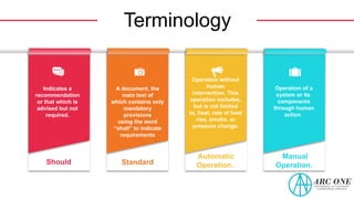
Indicates a
recommendation
or thatwhich is
advised but not
required.
Should
A document, the
main text of
which contains only
mandatory
provisions
using the word
“shall” to indicate
requirements
Standard
Operation without
human
intervention. This
operation includes,
but is not limited
to, heat, rate of heat
rise, smoke, or
pressure change.
Automatic
Operation.
Operation of a
system or its
components
through human
action.
Manual
Operation.
7.
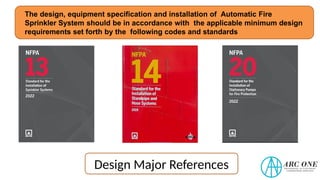
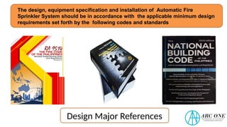
The design, equipmentspecification and installation of Automatic Fire
Sprinkler System should be in accordance with the applicable minimum design
requirements set forth by the following codes and standards
Design Major References
8.
The design, equipmentspecification and installation of Automatic Fire
Sprinkler System should be in accordance with the applicable minimum design
requirements set forth by the following codes and standards
Design Major References
9.
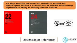
The design, equipmentspecification and installation of Automatic Fire
Sprinkler System should be in accordance with the applicable minimum design
requirements set forth by the following codes and standards
Design Major References
10.
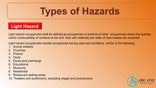
Types of Hazards
Lighthazard occupancies shall be defined as occupancies or portions of other occupancies where the quantity
and/or combustibility of contents is low and fires with relatively low rates of heat release are expected.
Light hazard occupancies include occupancies having uses and conditions similar to the following:
1. Animal shelters
2. Churches
3. Prisons
4. Clubs
5. Eaves and overhangs
6. Educational
7. Museums
8. Residential
9. Restaurant seating areas
10. Theaters and auditoriums, excluding stages and prosceniums
Light Hazard
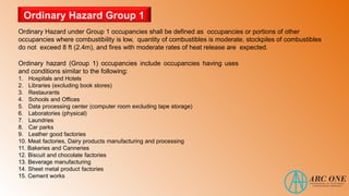
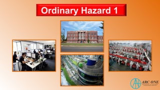
Ordinary Hazard underGroup 1 occupancies shall be defined as occupancies or portions of other
occupancies where combustibility is low, quantity of combustibles is moderate, stockpiles of combustibles
do not exceed 8 ft (2.4m), and fires with moderate rates of heat release are expected.
Ordinary hazard (Group 1) occupancies include occupancies having uses
and conditions similar to the following:
1. Hospitals and Hotels
2. Libraries (excluding book stores)
3. Restaurants
4. Schools and Offices
5. Data processing center (computer room excluding tape storage)
6. Laboratories (physical)
7. Laundries
8. Car parks
9. Leather good factories
10. Meat factories, Dairy products manufacturing and processing
11. Bakeries and Canneries
12. Biscuit and chocolate factories
13. Beverage manufacturing
14. Sheet metal product factories
15. Cement works
Ordinary Hazard Group 1
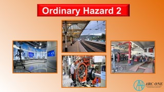
Ordinary Hazard underGroup 2 occupancies shall be defined as occupancies or portions of other occupancies
where the quantity and combustibility of contents are moderate to high, stockpiles do not exceed 12 ft (3.7 m),
and fires with moderate to high rates of heat release are expected.
Ordinary hazard (Group 2) occupancies include occupancies having uses and
conditions similar to the following:
1. Broadcasting and TV studios
2. Railway stations
3. Exhibition halls
4. Clothing factories, Weaving mills and Textile manufacturing
5. Furniture showrooms and upholstery shops with no plastic foams
6. Archives, Storage rooms, File rooms
7. Department stores and Shopping center
8. Corn mills, Dehydrated vegetable factory and Sugar factory
9. Glass factory, Tobacco products manufacturing
10. Radio equipment factory
11. Refrigerator and washing machine factory
12. Machine shops, Metal working, Wood products assembly
13. Paper and pulp mills, Plastic fabrication
14. Post offices, Printing and publishing
15. Automotive repair shops
16. Tire manufacturing
Ordinary Hazard Group 2
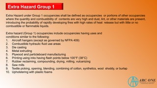
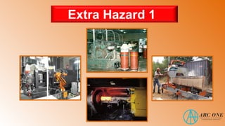
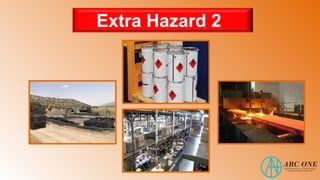
Extra Hazard Group1
Extra Hazard under Group 1 occupancies shall be defined as occupancies or portions of other occupancies
where the quantity and combustibility of contents are very high and dust, lint, or other materials are present,
introducing the probability of rapidly developing fires with high rates of heat release but with little or no
combustible or flammable liquids.
Extra hazard (Group 1) occupancies include occupancies having uses and
conditions similar to the following:
1. Aircraft hangars (except as governed by NFPA 409)
2. Combustible hydraulic fluid use areas
3. Die casting
4. Metal extruding
5. Plywood and particleboard manufacturing
6. Printing using inks having flash points below 100°F (38°C)
7. Rubber reclaiming, compounding, drying, milling, vulcanizing
8. Saw mills
9. Textile picking, opening, blending, combining of cotton, synthetics, wool shoddy, or burlap
10. Upholstering with plastic foams
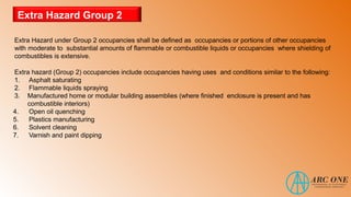
Extra Hazard Group2
Extra Hazard under Group 2 occupancies shall be defined as occupancies or portions of other occupancies
with moderate to substantial amounts of flammable or combustible liquids or occupancies where shielding of
combustibles is extensive.
Extra hazard (Group 2) occupancies include occupancies having uses and conditions similar to the following:
1. Asphalt saturating
2. Flammable liquids spraying
3. Manufactured home or modular building assemblies (where finished enclosure is present and has
combustible interiors)
4. Open oil quenching
5. Plastics manufacturing
6. Solvent cleaning
7. Varnish and paint dipping
Sprinkler System Failures
Thereare THREE principal causes of
unsatisfactory sprinkler performance:
1. A closed valve in the water supply
2. Inadequate water supply delivery
3.Occupancy changes negating the system
design
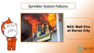
Sprinkler System Failures
•At least 38 persons were trapped and died during the
incident.
• The probable cause of the fire was faulty electrical wiring
due to malpractice of the renovation of the mall's third
floor.
• The IAATF later discovered that the mall's automatic fire
suppression system did not function in the third and
fourth floors as the valves of the fire sprinkler system
were closed.
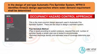
In the designof wet type Automatic Fire Sprinkler System, NFPA13
identifies three(3) design approaches where water demand requirement
shall be determined
OCCUPANCY HAZARD CONTROL APPROACH
This is the most common design approach used in Automatic Fire
Sprinkler System. There are two ways to design a sprinkler system:
Pipe Schedule Method
•Pipe is sized according to system pressure, required flow and number of
sprinkler heads a certain pipe size is tested to accommodate.
•Sprinkler discharge density and estimated area of coverage determine pipe
size.
27.
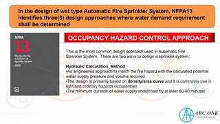
In the designof wet type Automatic Fire Sprinkler System, NFPA13
identifies three(3) design approaches where water demand requirement
shall be determined
OCCUPANCY HAZARD CONTROL APPROACH
This is the most common design approach used in Automatic Fire
Sprinkler System. There are two ways to design a sprinkler system:
Hydraulic Calculation Method
•An engineered approach to match the fire hazard with the calculated potential
water supply pressure and volume required
•The design is primarily based on density/area curve and it is commonly use in
light and ordinary hazards occupancies
•The minimum duration of water supply should last by at least 60-90 minutes
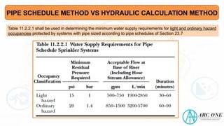
PIPE SCHEDULE METHODVS HYDRAULIC CALCULATION METHOD
Pipe schedule method –uses tables that
indicate that steel pipe of certain size will
supply a certain number of heads.
In pipe schedules, only a limited number of
sprinklers may be supplied by a given pipe
size.
In a hydraulically calculated system, there is no limit to the
number of sprinklers that can be supplied by any size pipe,
the size is solely dictated by the rate of flow.
However, the total square footage covered by a single fire
riser is restricted, normally to 52,000 ft2, except 40,000 ft2in
storage occupancies. The calculations simply must prove that
the pipe size and configuration will be adequate to deliver the
required densities from the available water supply.
Therefore, pipe is sized to deliver the required flow and
pressure each head in the area of operation and size the pipe
back to the system water supply in order to deliver the
demand for the area of operation.
30.
PIPE SCHEDULE METHODVS HYDRAULIC CALCULATION METHOD
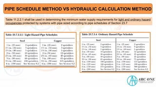
Table 11.2.2.1 shall be used in determining the minimum water supply requirements for light and ordinary hazard
occupancies protected by systems with pipe sized according to pipe schedules of Section 23.7
31.
PIPE SCHEDULE METHODVS HYDRAULIC CALCULATION METHOD
Table 11.2.2.1 shall be used in determining the minimum water supply requirements for light and ordinary hazard
occupancies protected by systems with pipe sized according to pipe schedules of Section 23.7
32.
PIPE SCHEDULE METHODVS HYDRAULIC CALCULATION METHOD
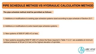
The pipe schedule method shall be permitted as follows:
1. Additions or modifications to existing pipe schedule systems sized according to pipe schedule of Section 23.7.
2. Additions or modifications to extra hazard pipe schedule systems.
3. New systems of 5000 ft² (465 m²) or less.
4. New systems exceeding 5000 ft² (465 m²) where the flows required in Table 11.2.2.1 are available at minimum
residual pressure of 50 psi (3.4 bar) at the highest elevation of sprinkler.
33.
PIPE SCHEDULE METHODVS HYDRAULIC CALCULATION METHOD
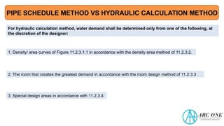
For hydraulic calculation method, water demand shall be determined only from one of the following, at
the discretion of the designer:
1. Density/ area curves of Figure 11.2.3.1.1 in accordance with the density area method of 11.2.3.2.
2. The room that creates the greatest demand in accordance with the room design method of 11.2.3.3
3. Special design areas in accordance with 11.2.3.4
34.
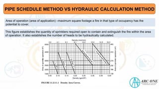
Area of operation(area of application) –maximum square footage a fire in that type of occupancy has the
potential to cover.
This figure establishes the quantity of sprinklers required open to contain and extinguish the fire within the area
of operation. It also establishes the number of heads to be hydraulically calculated.
PIPE SCHEDULE METHOD VS HYDRAULIC CALCULATION METHOD
35.
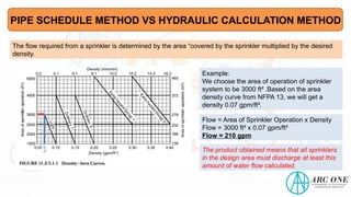
The flow requiredfrom a sprinkler is determined by the area “covered by the sprinkler multiplied by the desired
density.
0.07
Example:
We choose the area of operation of sprinkler
system to be 3000 ft² .Based on the area
density curve from NFPA 13, we will get a
density 0.07 gpm/ft².
Flow = Area of Sprinkler Operation x Density
Flow = 3000 ft² x 0.07 gpm/ft²
Flow = 210 gpm
The product obtained means that all sprinklers
in the design area must discharge at least this
amount of water flow calculated.
PIPE SCHEDULE METHOD VS HYDRAULIC CALCULATION METHOD
36.
In the designof wet type Automatic Fire Sprinkler System, NFPA13
identifies three(3) design approaches where water demand requirement
shall be determined
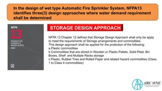
STORAGE DESIGN APPROACH
NFPA 13 Chapter 12 defines that Storage Design Approach shall only be apply
to meet the requirements of Storage arrangements and commodities.
This design approach shall be applied for the protection of the following:
a.Plastic commodities
b.Commodities that are stored in Wooden or Plastic Pallets, Solid Piled, Bin
Boxes, Shelf and Multiple Racks storage
c.Plastic, Rubber Tires and Rolled Paper and related hazard commodities (Class
1 to Class 4 commodities)
37.
In the designof wet type Automatic Fire Sprinkler System, NFPA13
identifies three(3) design approaches where water demand requirement
shall be determined
STORAGE DESIGN APPROACH
NFPA 13 mandatory requirements:
a.This design approach requires the use of Early Suppression Fast-Response
(ESFR) and Large Drop Sprinklers.
b.Aside from Automatic Sprinklers, NFPA 13 requires the installation of Automatic
Medium and High-Expansion Foam System in accordance with NFPA 11A.
c.In the Density/Area Curve, storage design should start with Ordinary Hazard 2
curve.
d.The minimum duration of water supply should last by at least 120-180 minutes.
38.
In the designof wet type Automatic Fire Sprinkler System, NFPA13
identifies three(3) design approaches where water demand requirement
shall be determined
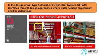
STORAGE DESIGN APPROACH
STORAGE SPRINKLER SYSTEM IN-RACK SPRINKLER SYSTEM
39.
In the designof wet type Automatic Fire Sprinkler System, NFPA13
identifies three(3) design approaches where water demand requirement
shall be determined
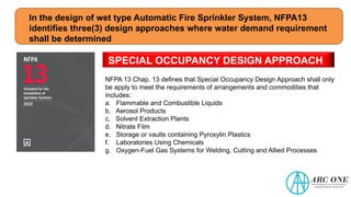
SPECIAL OCCUPANCY DESIGN APPROACH
NFPA 13 Chap. 13 defines that Special Occupancy Design Approach shall only
be apply to meet the requirements of arrangements and commodities that
includes:
a. Flammable and Combustible Liquids
b. Aerosol Products
c. Solvent Extraction Plants
d. Nitrate Film
e. Storage or vaults containing Pyroxylin Plastics
f. Laboratories Using Chemicals
g. Oxygen-Fuel Gas Systems for Welding, Cutting and Allied Processes
40.
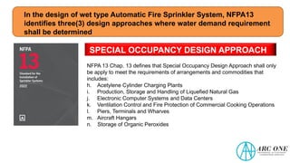
In the designof wet type Automatic Fire Sprinkler System, NFPA13
identifies three(3) design approaches where water demand requirement
shall be determined
SPECIAL OCCUPANCY DESIGN APPROACH
NFPA 13 Chap. 13 defines that Special Occupancy Design Approach shall only
be apply to meet the requirements of arrangements and commodities that
includes:
h. Acetylene Cylinder Charging Plants
i. Production, Storage and Handling of Liquefied Natural Gas
j. Electronic Computer Systems and Data Centers
k. Ventilation Control and Fire Protection of Commercial Cooking Operations
l. Piers, Terminals and Wharves
m. Aircraft Hangars
n. Storage of Organic Peroxides
41.
In the designof wet type Automatic Fire Sprinkler System, NFPA13
identifies three(3) design approaches where water demand requirement
shall be determined
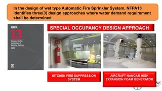
SPECIAL OCCUPANCY DESIGN APPROACH
KITCHEN FIRE SUPPRESSION
SYSTEM
AIRCRAFT HANGAR HIGH
EXPANSION FOAM GENERATOR
42.
In the designof wet type Automatic Fire Sprinkler System, NFPA13
identifies three(3) design approaches where water demand requirement
shall be determined
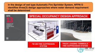
SPECIAL OCCUPANCY DESIGN APPROACH
FM 200 FIRE SUPPRESION
SYSTEM
TRUCK LOADING TERMINALS
FIRE SUPPRESSION SYSTEM
43.
In the designof wet type Automatic Fire Sprinkler System, NFPA13
identifies three(3) design approaches where water demand requirement
shall be determined
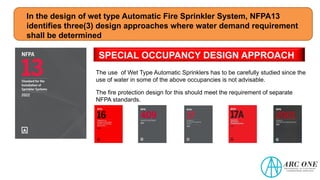
SPECIAL OCCUPANCY DESIGN APPROACH
The use of Wet Type Automatic Sprinklers has to be carefully studied since the
use of water in some of the above occupancies is not advisable.
The fire protection design for this should meet the requirement of separate
NFPA standards.
DETERMINING THE DESIGNAREA
UNDERESTIMATING THE HAZARD
POSES A HIGH RISK OF
FIRE TO OVERPOWER THE FIRE
SPRINKLERS – THIS WILL RESULT TO
LOSS OF PROPERTY OR LIFE
46.
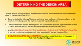
DETERMINING THE DESIGNAREA
Once the sprinkler spacing and piping layout has been proposed in conformance with the requirements of
NFPA 13, the design engineer should:
a. Demonstrate that the delivery of the prescribed rate of water application will be accomplished for the
sprinklers in the design area that might be reasonably expected to operate.
b. Demonstrate that the shape of the design area and location of the sprinklers, regardless of the location
of the fire within the building, will be adequately supplied with water in the event of fire.
c. The DESIGN AREA SHOULD BE THE MOST CHALLENGING AND FARTHEST LOCATION
of sprinkler in order to ensure that enough water is supplied if it opens in the event of fire.
OCCUPANCY HAZARD CLASSIFICATION is one the most critical steps in the design of
Automatic Fire Sprinkler System.
47.
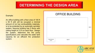
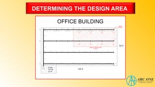
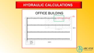
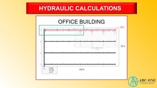
DETERMINING THE DESIGNAREA
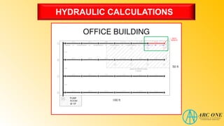
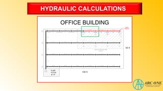
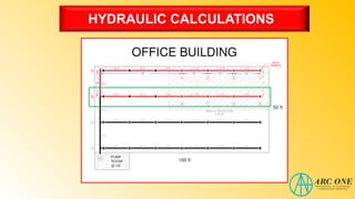
Example:
An office building with a floor area of 100 ft
x 50 ft with will be occupied a minimal
amount of no/ low combustibility materials,
is to be protected by an automatic sprinkler
system. Assume building has 5 floors with
ceiling height of 12 ft on each floor. Design
the system, determine the fire pump
specifications and calculate the water tank
capacity for an efficient fire protection
system.
48.
DETERMINING THE DESIGNAREA
As per NFPA 13 Section 8.6.3
The maximum distance from
sprinkler to a wall shall not exceed
one-half of the allowable distance
between sprinklers as indicated in
Table 8.6.2.2 (a) through Table
8.6.2.2 (d). The distance from the
wall to the sprinkler shall be
measured perpendicular to the wall.
Sprinklers shall be located a
minimum of 4 inches from a wall.
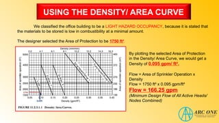
USING THE DENSITY/AREA CURVE
We classified the office building to be a LIGHT HAZARD OCCUPANCY, because it is stated that
the materials to be stored is low in combustibility at a minimal amount.
The designer selected the Area of Protection to be 1750 ft².
0.095
1750
By plotting the selected Area of Protection
in the Density/ Area Curve, we would get a
Density of 0.095 gpm/ ft².
Flow = Area of Sprinkler Operation x
Density
Flow = 1750 ft² x 0.095 gpm/ft²
Flow = 166.25 gpm
(Minimum Design Flow of All Active Heads/
Nodes Combined)
51.
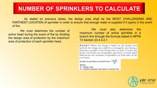
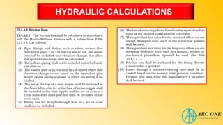
NUMBER OF SPRINKLERSTO CALCULATE
As stated on previous slides, the design area shall be the MOST CHALLENGING AND
FARTHEST LOCATION of sprinkler in order to ensure that enough water is supplied if it opens in the event
of fire.
We must determine the number of
active head during the event of fire by dividing
the design area of protection by the maximum
area of protection of each sprinkler head.
We must also determine the
maximum number of active sprinkles in a
branch line through the formula stated in NFPA
13 Section 23.4.4.2.1
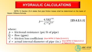
HYDRAULIC CALCULATIONS
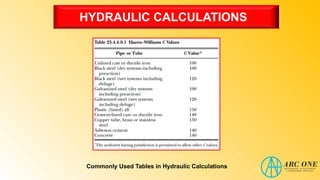
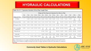
NFPA 13Section 23.4 states that pipe friction losses shall be determined on the basis of
Hazen- Williams formula.
(from NFPA 13 Table A.6.3.2
or Table A.6.3.5)
(from NFPA 13 Table 23.4.4.8.1)
54.
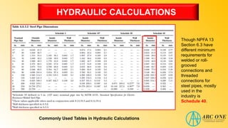
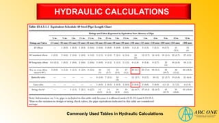
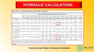
HYDRAULIC CALCULATIONS
Though NPFA13
Section 6.3 have
different minimum
requirements for
welded or roll-
grooved
connections and
threaded
connections for
steel pipes, mostly
used in the
industry is
Schedule 40.
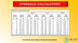
Commonly Used Tables in Hydraulic Calculations
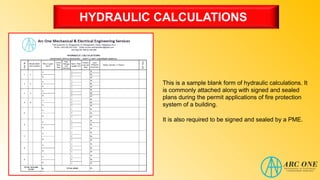
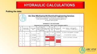
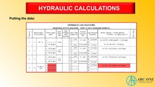
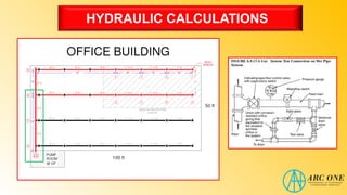
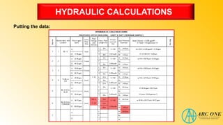
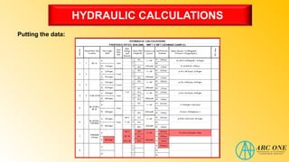
HYDRAULIC CALCULATIONS
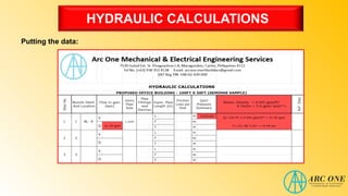
This isa sample blank form of hydraulic calculations. It
is commonly attached along with signed and sealed
plans during the permit applications of fire protection
system of a building.
It is also required to be signed and sealed by a PME.
60.
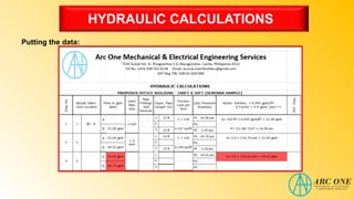
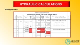
HYDRAULIC CALCULATIONS
Let ustry to fill up the Hydraulic Calculations Form based on the example given on the previous
slides.
Gathering the data we have so far:
• Office Building considered to be Light Hazard.
• Sprinkler Distance in Same Branch Line is 15 ft.
• Sprinkler Distance from Other Branch Line is 15 ft.
• Sprinkler Area of Protection is 225 ft².
• Design Area of Protection is 1750 ft².
• Total Number of Active Sprinklers is 8 sprinkler heads/ nodes.
• Total Number of Active Sprinklers per Branch line is 4 sprinkler heads/ nodes.
61.
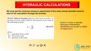
HYDRAULIC CALCULATIONS
We mustget the minimum pressure requirement of the most remote sprinkler head as
start of our calculation through the formula:
Where: K- Factor or Sprinkler
Discharge Characteristics
Identification can be seen on NFPA
13 Table 6.2.3.1
P= )² or Q= K
62.
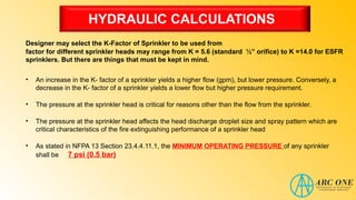
HYDRAULIC CALCULATIONS
Designer mayselect the K-Factor of Sprinkler to be used from
factor for different sprinkler heads may range from K = 5.6 (standard ½” orifice) to K =14.0 for ESFR
sprinklers. But there are things that must be kept in mind.
• An increase in the K- factor of a sprinkler yields a higher flow (gpm), but lower pressure. Conversely, a
decrease in the K- factor of a sprinkler yields a lower flow but higher pressure requirement.
• The pressure at the sprinkler head is critical for reasons other than the flow from the sprinkler.
• The pressure at the sprinkler head affects the head discharge droplet size and spray pattern which are
critical characteristics of the fire extinguishing performance of a sprinkler head
• As stated in NFPA 13 Section 23.4.4.11.1, the MINIMUM OPERATING PRESSURE of any sprinkler
shall be 7 psi (0.5 bar)
63.
HYDRAULIC CALCULATIONS
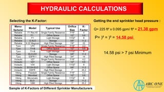
Selecting theK-Factor:
Sample of K-Factors of Different Sprinkler Manufacturers
Getting the end sprinkler head pressure :
P= )² = )² = 14.58 psi
Q= 225 ft² x 0.095 gpm/ ft² = 21.38 gpm
14.58 psi > 7 psi Minimum
HYDRAULIC CALCULATIONS
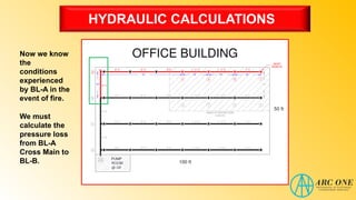
Now weknow
the
conditions
experienced
by BL-A in the
event of fire.
We must
calculate the
pressure loss
from BL-A
Cross Main to
BL-B.
84.
HYDRAULIC CALCULATIONS
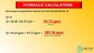
Since wealready know the conditions of BL-A, we must also get the conditions experienced by BL-B.
This K-Factor will be used also when
determining the flow of the 2nd
Branch line
or BL-B.
K- Factor =
18.48 gpm /
To get this, first, we must compute for the
K-Factor of BL-A with flow conditions of
94.64 gpm and pressure of 26.23 psi.
85.
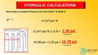
HYDRAULIC CALCULATIONS
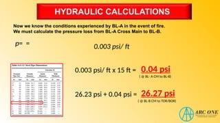
Now weknow the conditions experienced by BL-A in the event of fire.
We must calculate the pressure loss from BL-A Cross Main to BL-B.
p= = 0.003 psi/ ft
0.003 psi/ ft x 15 ft = 0.04 psi
26.23 psi + 0.04 psi = 26.27 psi
( @ BL-B CM to TOR/BOR)
( @ BL- A CM to BL-B)
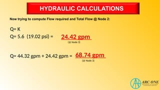
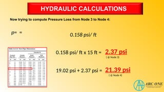
HYDRAULIC CALCULATIONS
Knowing thetotal flow condition of the cross main. We can calculate the
pressure loss from BL-B Cross Main to the Top of Riser (TOR)
p= = 0.012 psi/ ft
0.012 psi/ ft x (33 ft + 22ft) = 0.66 psi
26.27 psi + 0.66 psi = 26.93 psi
( @ TOR/ BOR to Pump)
( @ BL- B CM to TOR/BOR)
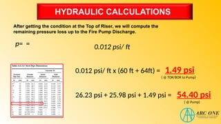
HYDRAULIC CALCULATIONS
After gettingthe condition at the Top of Riser, we will compute the
remaining pressure loss up to the Fire Pump Discharge.
p= = 0.012 psi/ ft
0.012 psi/ ft x (60 ft + 64ft) = 1.49 psi
26.23 psi + 25.98 psi + 1.49 psi = 54.40 psi
( @ Pump)
( @ TOR/BOR to Pump)
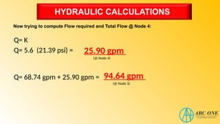
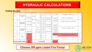
HYDRAULIC CALCULATIONS
We alreadygot the Flow and Pressure Requirements for the Sprinkler
System of the Building.
Since the common set up of Fire Protection System is a combined system
wherein the fire pump is supplying the demand requirement of both the sprinkler
systems and stand pipe / hose systems. We must add the Hose Stream
Allowance in the Pump Capacity.
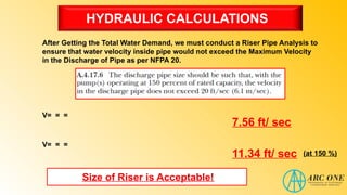
HYDRAULIC CALCULATIONS
After Gettingthe Total Water Demand, we must conduct a Riser Pipe Analysis to
ensure that water velocity inside pipe would not exceed the Maximum Velocity
in the Discharge of Pipe as per NFPA 20.
V= = =
7.56 ft/ sec
V= = =
11.34 ft/ sec (at 150 %)
Size of Riser is Acceptable!
101.
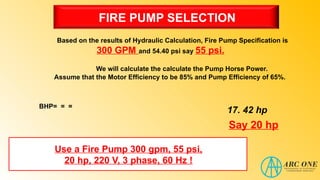
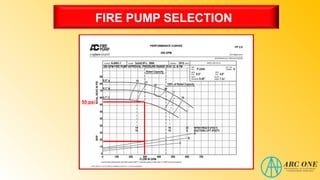
FIRE PUMP SELECTION
Basedon the results of Hydraulic Calculation, Fire Pump Specification is
300 GPM and 54.40 psi say 55 psi.
BHP= = =
We will calculate the calculate the Pump Horse Power.
Assume that the Motor Efficiency to be 85% and Pump Efficiency of 65%.
17. 42 hp
Say 20 hp
Use a Fire Pump 300 gpm, 55 psi,
20 hp, 220 V, 3 phase, 60 Hz !
SIZING THE FIRETANK
After determining the specifications of Fire Pump, you must design a Tank sized
capable of holding enough water supply as per guidelines of NFPA 13.
300 gpm x 30 mins = 9000 gals
Tank Dimensions: 3mL x 4mW x 3mH
9510 Gallons