
Recommended
Recommended
More Related Content
Similar to Fire Safety (Common Design Issues) .pptx
Similar to Fire Safety (Common Design Issues) .pptx (20)
Recently uploaded
Recently uploaded (20)
Fire Safety (Common Design Issues) .pptx
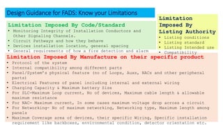
- 1. Limitation Imposed By Code/Standard • Monitoring Integrity of Installation Conductors and Other Signaling Channels. • Circuit Pathways and how they behave • Devices installation location, general spacing • General requirements of how a fire detection and alarm system will function Limitation Imposed By Manufacture on their specific product • Protocol of the system • Internal compatibility among different parts • Panel/System’s physical feature (no of Loops, Auxs, NACs and other peripheral parts) • Electrical Features of panel including internal and external wiring • Charging Capacity & Maximum battery Size • For SLC-Maximum Loop current, No of devices, Maximum cable length & allowable maximum resistance • For NAC- Maximum current, In some cases maximum voltage drop across a circuit • For Networking- No of maximum networking, Networking type, Maximum length among panels • Maximum Coverage area of devices, their specific Wiring, Specific installation requirement like backboxes, environmental condition, detector orientation etc. Limitation Imposed By Listing Authority • Listing conditions • Listing standard • Listing Intended use • Compatibility Design Guidance for FADS: Know your Limitations
- 2. Selection of Sprinkler system Selection of Design Philosophy Requirement determination following Building Code Design Occupancy selection as per NFPA-13 Determine the Design criteria (ESFR/CMDA/CMSA/SS U) Selection of sprinkler based on the characteristics (Suitable for installation) There is another step that is selecting the type of function- Wet, Dry, Pre- action, Deluge system Check the datasheet, if sprinkler selected is appropriate to use in selected design occupancy K- Factor Temp. rating Response Type Orifice Size Installation orientation Design Notes: • Check Design occupancy • Design hydraulic requirements • Check Ambient ceiling temp. • Ceiling geometry Spray Pattern Listing certificate must Reflect some of the characteristics mentioned here.
- 3. Calculation of Sprinkler system Design Notes: • Remote Area Selection • Most Demanding • Min working pressure • Design Area & Density or Other design criteria • Maximum Working Major Issues Hydraulic calculation done in a software program is a simulation demonstration of how the system will work in case of sprinkler activation. So, inclusion of all nodes in drawing with adequate information (pipe length, size, elevation) through isometric and Nodal diagram is very important. As inclusion of all fittings and pipes in calculation input. Ensure hydraulic calculation summary address this issues. Min Working pressure for CMDA sprinkler is 7 Psi. However, ESFR sprinkler are designed with much higher min. operating pressure as high a 3 BAR Hydraulic calculation with fixed flow (same) in all sprinkler is not acceptable, because it is impossible that all sprinkler will operate with minimum required working pressure at a same time Remote area selection shall be made with rectangular area with the larger length dimension parallel to the branch lines, that captures as many sprinklers as it can along the branch line. Check fire pump churn pressure. Check static pressure (Maximum working pressure) working at a sprinkler system at any point.
- 4. Major Sprinkler system Installation Issues-1 Long sprigs been used in sprinkler installation with severely deflected condition from its perpendicular position to the branch line causing it to have a different discharge pattern development than the design intended. Additionally, long sprigs are often found unsupported/unrestrained against lateral movement. Design Notes: Sprigs 4 ft (1.2 m) or longer shall be restrained against lateral movement Design Notes: Upright sprinklers shall be installed with the frame arms parallel to the branch line, unless specifically listed for other orientation. Upright sprinklers are installed with the frame arms not parallel to branch line causing double obstruction in discharge pattern.
- 5. Major Sprinkler system Installation Issues-2 Sprinkler head has been installed without any reducer inserted in the end of the branch line to reduce the pipe size from the larger tapered fitting to the smaller diameter pipe increasing the friction loss and turbulence in the pipe which affects water distribution onto a fire from a sprinkler. Design Notes: 6.4.7.1 Unless the requirements of 6.4.7.2 or 6.4.7.3 are met, a one-piece reducing fitting shall be used wherever a change is made in the size of the pipe. 6.4.7.2 Hexagonal or face bushings shall be permitted in reducing the size of openings of fittings when standard fittings of the required size are not available.
- 6. Major Sprinkler system Installation Issues-3 Return bends were not used during the installation of pendant sprinklers Design Notes: 8.15.19.1 Unless the requirements of 8.15.19.3, 8.15.19.4, or8.15.19.5 are met, return bends shall be used where e pendent sprinklers are supplied from a raw water source, a mill pond, or open-top reservoirs. 8.15.19.2 Return bends shall be connected to the top of branch lines in order to avoid accumulation of sediment in the drop nipples in accordance with Figure 8.15.19.2. 8.15.19.3 Return bends shall not be required for deluge systems. 8.15.19.4 Return bends shall not be required where dry pendent sprinklers are used. 8.15.19.5 Return bends shall not be required for wet pipe systems where sprinklers with a nominal K-factor of K-11.2 (160) or larger are used. Did you know? Design Notes: (Additional) • For new systems, outlet size shall be minimum of 1 in, and we can use hexagonal bushings to accommodate sprinklers attached directly to branch line fittings to allow for future system modifications. • For existing systems (pipe schedule) riser nipples less than 1" are allowed but shall not exceed 10 cm in length. • For existing systems (Hydraulically calculated) riser nipples less than 1" are allowed but shall not exceed 10 cm in length and shall be considered in hydraulic calculations. • Hangers are required to prevent upward movement on the arm over piping when: • the arm over is steel, exceeds 12 inches, and system pressure exceeds 100 psi (NFPA 13 2002/2007/2010/2013/2016 9.2.3.5.2) • the arm over is steel and exceeds 24 inches (NFPA 13 2002/2007/2010/2013/2016 9.2.3.5)
- 7. Major Sprinkler system Installation Issues-4 To be considered obstructed, the construction elements must be composed of “beams, trusses, or other members” that will impede heat flow, water distribution, or otherwise affect the ability of the sprinkler to control or suppress the fire. [3.7.1] Obstruction to impede heat flow reaching the sprinkler Obstruction to sprinkler discharge pattern development. Obstructions that Prevent Sprinkler Discharge from Reaching Hazard
- 8. Major Sprinkler system Installation Issues-4. Continue
- 9. Major Sprinkler system Installation Issues-5 Design Notes: • Floor control valve assembly shall be provided in buildings exceeding two stories. (16.9.11.1) • For isolation, control, and annunciation of water flow on each floor level. Where Not Required? • Floor control valve assembly shall not be required where sprinklers on the top level of a multistory building are supplied by piping on the floor below. (16.9.11.1) • Floor control valve assembly shall not be required where the total area of all floors combined does not exceed the system protection area limitations. (16.9.11.3) System Protection Area Limitation: The maximum floor area on any one floor to be protected by sprinklers supplied by any one sprinkler system riser or combined system riser shall be as follows: • For light hazard occupancies:52,000 Sft. • For ordinary hazard occupancies: 52,000 Sft. • For Extra hazard occupancies: 40,000 Sft. • For high piled storage: 40,000 Sft. • For in-rack storage: 40,000 Sft. Check Valves are not included as a part of Floor/Zone control valve assembly