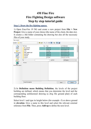
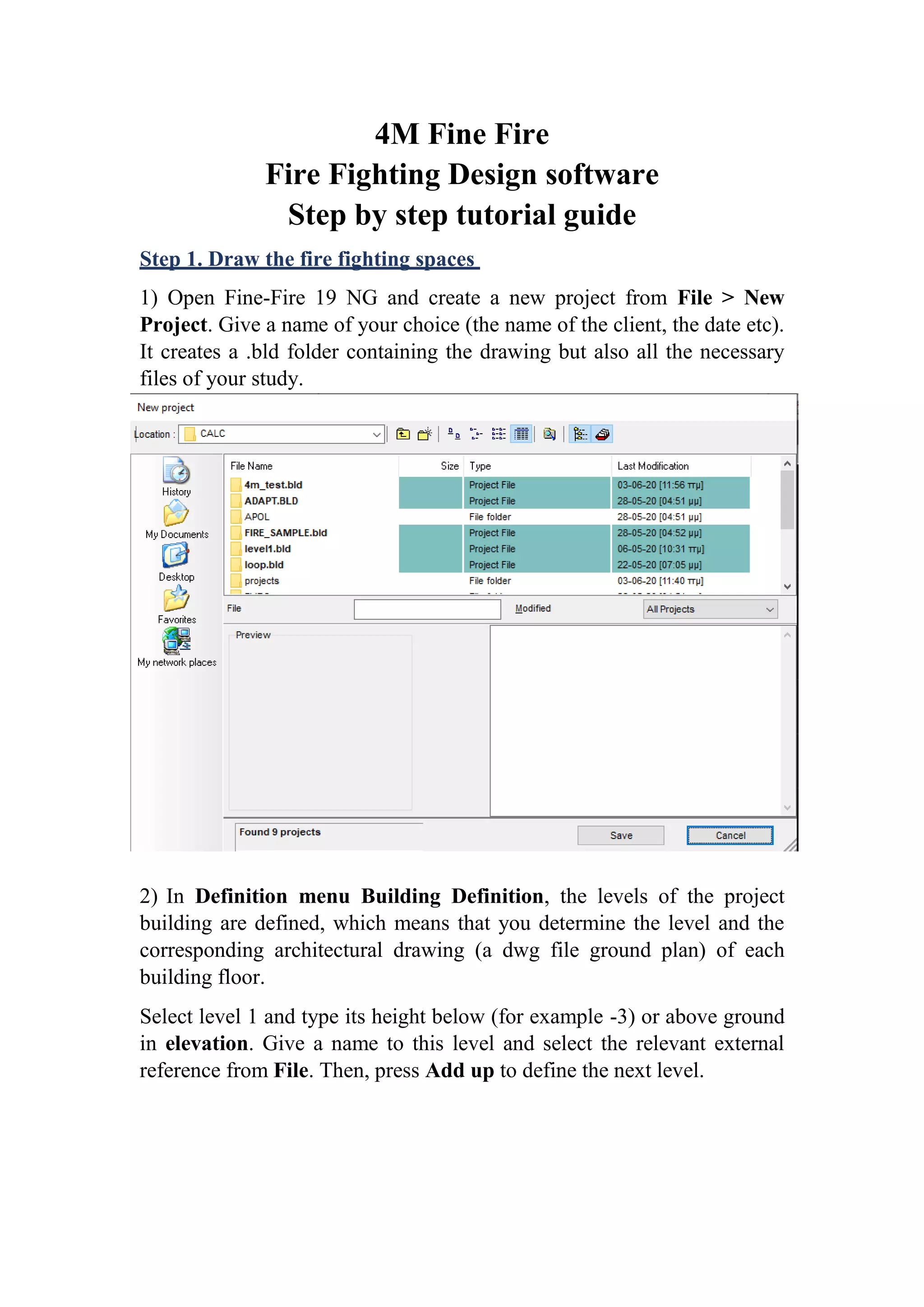
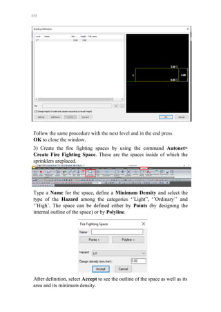
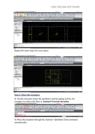
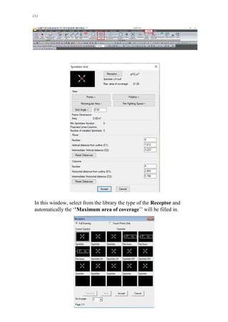
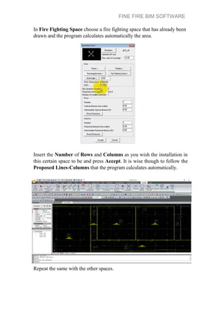
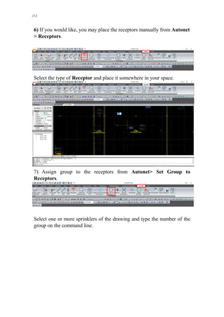
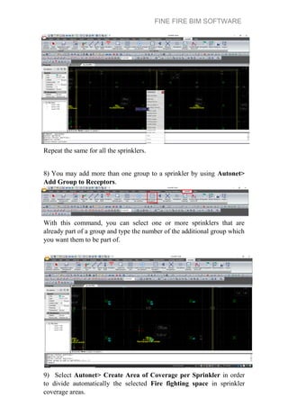
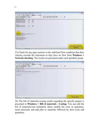
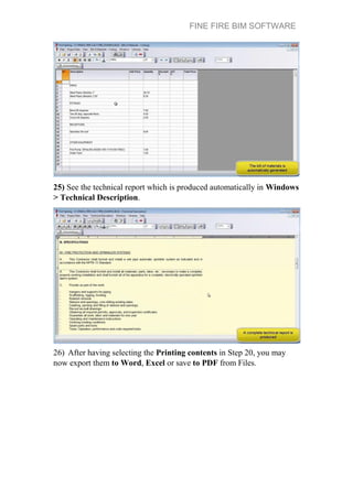
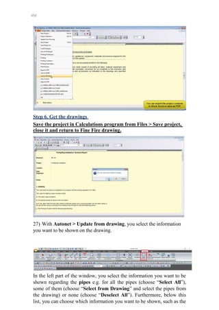
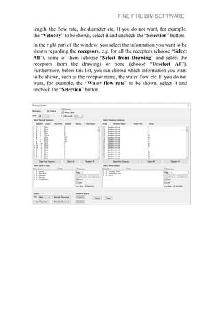
4M Fine Fire
Fire Fighting Design software
Step by step tutorial guide
Step 1. Draw the fire fighting spaces
1) Open Fine-Fire 19 NG and create a new project from File > New
Project. Give a name of your choice (the name of the client, the date etc).
It creates a .bld folder containing the drawing but also all the necessary
files of your study.
2) In Definition menu Building Definition, the levels of the project
building are defined, which means that you determine the level and the
corresponding architectural drawing (a dwg file ground plan) of each
building floor.
Select level 1 and type its height below (for example -3) or above ground
in elevation. Give a name to this level and select the relevant external
reference from File. Then, press Add up to define the next level.
4M
Follow the same procedure with the next level and in the end press
OK to close the window.
3) Create the fire fighting spaces by using the command Autonet>
Create Fire Fighting Space. These are the spaces inside of which the
sprinklers areplaced.
Type a Name for the space, define a Minimum Density and select the
type of the Hazard among the categories ‘’Light”, ‘’Ordinary’’ and
‘’High’. The space can be defined either by Points (by designing the
internal outline of the space) or by Polyline.
After definition, select Accept to see the outline of the space as well as its
area and its minimum density.
FINE FIRE BIM SOFTWARE
Repeat the same steps for every space.
Step 2. Place the receptors
4) Set the elevation where the sprinklers and the piping will be, for
example 4 m above the floor in Autonet>Current elevation.
5) Place the receptors through the Autonet> Sprinklers Grid command
automatically.
4M
In this window, select from the library the type of the Receptor and
automatically the ‘’Maximum area of coverage’’ will be filled in.
FINE FIRE BIM SOFTWARE
In Fire Fighting Space choose a fire fighting space that has already been
drawn and the program calculates automatically the area.
Insert the Number of Rows and Columns as you wish the installation in
this certain space to be and press Accept. It is wise though to follow the
Proposed Lines-Columns that the program calculates automatically.
Repeat the same with the other spaces.
4M
6) If you would like, you may place the receptors manually from Autonet
> Receptors.
Select the type of Receptor and place it somewhere in your space.
7) Assign group to the receptors from Autonet> Set Group to
Receptors.
Select one or more sprinklers of the drawing and type the number of the
group on the command line.
FINE FIRE BIM SOFTWARE
Repeat the same for all the sprinklers.
8) You may add more than one group to a sprinkler by using Autonet>
Add Group to Receptors.
With this command, you can select one or more sprinklers that are
already part of a group and type the number of the additional group which
you want them to be part of.
9) Select Autonet> Create Area of Coverage per Sprinkler in order
to divide automatically the selected Fire fighting space in sprinkler
coverage areas.
4M
The program checks if each sprinkler can cover its area and if it can, the
coverage outlines are in green color. If it cannot, the outlines are in red
color.
Step 3. Draw the network
10) You can draw any type of pipe network you wish (trees, loops, grids,
etc) starting from Autonet> Pipe for the horizontal pipes. With
successive clicks on a plan view, you create yournetwork.
11) Connect automatically the receptor with the horizontal network by
Autonet> Connect Receptors to Existing pipe. Select the receptor, as
told, in the command line, then the pipe and it isconnected.
FINE FIRE BIM SOFTWARE
Repeat the same for every connector.
12) Delete the extra/useless parts of piping network by selecting them and
pressingDel.
13) Draw a vertical pipe starting from elevation 4m and ending in 0 by
Autonet> Pipe, selecting the end of the horizontal network and typing
@0,0,-4.00.
Then, continue in designing the horizontal network (now it is in 0m
above ground) in order to place the supply point by Autonet> Supply
Point.
14) Run Autonet> Network Recognition in order to convert the
network in the required standard pattern and update appropriately the
calculation sheet.
4M
During updating, junction points and receptors are numbered on the
ground plan automatically, thanks to the advanced BIM technology.
Note that if a receptor is not numbered, it means that it is not connected to
the network. Besides, if a network section has a different color, it is not
correctly connected to the network.
Step 4. Get the calculations
15) Select Autonet> Calculations, an option which leads you to the
corresponding calculating environment.
A new window of the current application is “opening” and FINE FIRE
remains "open".
FINE FIRE BIM SOFTWARE
16) In calculations program, by selecting Files > Update from Drawing,
the project worksheets are updated with the drawing data.
In the next two questions about project changes save and calculations
run, press yes.
17) Fill in the Project Data > Network with the general network data
that you should specify and apply to your project.
Some typical values appear on the next figure. The most important option
is the Calculation method, which can be NFPA Ordinary Hazard Pipe
Schedule, Hydraulic Calculations, Fully calculated systems NFPA 13,
Fully calculated systems EN 12845, Fully calculated systems AS 2118,
Fully calculated systems BS 9251, Fully calculated systems FM
Global, or Fully calculated systems CEA4001.
4M
18) Then, you can view the calculations in Windows > Calculations
sheet.
The Calculation Sheet of the Fire Fighting System is the core of the
calculations. Therefore, each row of this sheet corresponds to a different
network section while each column refers to the data that will ensue
automatically during the procedure of data completing.
FINE FIRE BIM SOFTWARE
You change the type of receptors, pipe size, type of fittings etc. and the
modification updates the calculation sheet in real time.
For example, you may add fittings in a network section by pressing … in
column Type of fittings.
4M
19) Select Files > Print Preview in order to examine the complete
project issue that appears on the screen, exactly as it will be printed, page
to page.
The detailed results for each group are shown separately.
Control what items are going to be printed in the issue from Files >
Printing Contents.
FINE FIRE BIM SOFTWARE
Step 5. Select the fire pump
20) In Windows > Fire pump calculation , you can select the fire pump,
calculate the motor power and run an NPSH (Net Positive Suction Head)
check.
With red color, the detailed calculation data of fire pump, based on most
favourable and most unfavourable groups, appear.
4M
Choose the appropriate type of fire pump from Type of selected Pump,
either by selecting Fire pump Selection or Fire pump Selection by
Hydraulic Solution Method.
With Fire pump Selection by Hydraulic Solution Method the program
displays only the pumps that can provide the required power.
FINE FIRE BIM SOFTWARE
When you select the fire pump, you can see on the right side of the
window its pump curve.
4M
21) Check the NPSH (Net Positive Suction Head) in the next tab, by
filling in the data that correspond to the project. Some indicative values
appear to the next figure.
You can see, also, the NPSH curve under the pipe curve as well the
curve of the motor with the motor power calculation.
FINE FIRE BIM SOFTWARE
22) From Windows > Sections Frictions Drop, you can view the total
frictions in all sections starting from the pump and ending in each
terminalnode.
When one of the methods Fully calculated systems NFPA 13, Fully
calculated systems EN 12845, Fully calculated systems AS 2118, Fully
calculated systems BS 9251, Fully calculated systems FM Global or Fully
calculated systems CEA 4001 has been selected, you can view the total
frictions for the stabilized flow condition for each sprinkler group
separately, as well as the most favourable and unfavourable groups
with their required pressures, their capacities and the sections with the
highest pressure drop.
4M
23) Check for any pipe sections in the stabilized flow condition that their
velocity exceeds the maximum or they have no flow from Windows >
Network checking. The results are presented under each sprinkler group.
24) The bill of materials-costing results regarding the specific project is
presented in Windows > Bill of materials - Costing. You can edit the
bill of materials-cost estimation sheet, modify the costs or quantities,
insert discounts and add jobs or materials followed by their costs and
quantities.
FINE FIRE BIM SOFTWARE
25) See the technical report which is produced automatically in Windows
> Technical Description.
26) After having selecting the Printing contents in Step 20, you may
now export them to Word, Excel or save to PDF from Files.
4M
Step 6. Get the drawings
Save the project in Calculations program from Files > Save project,
close it and return to Fine Fire drawing.
27) With Autonet > Update from drawing, you select the information
you want to be shown on the drawing.
In the left part of the window, you select the information you want to be
shown regarding the pipes e.g. for all the pipes (choose “Select All”),
some of them (choose “Select from Drawing” and select the pipes from
the drawing) or none (choose “Deselect All”). Furthermore, below this
list, you can choose which information you want to be shown, such as the
FINE FIRE BIM SOFTWARE
length, the flow rate, the diameter etc. If you do not want, for example,
the “Velocity” to be shown, select it and uncheck the “Selection” button.
In the right part of the window, you select the information you want to be
shown regarding the receptors, e.g. for all the receptors (choose “Select
All”), some of them (choose “Select from Drawing” and select the
receptors from the drawing) or none (choose “Deselect All”).
Furthermore, below this list, you can choose which information you want
to be shown, such as the receptor name, the water flow etc. If you do not
want, for example, the “Water flow rate” to be shown, select it and
uncheck the “Selection” button.
4M
Finally, to place the information on the drawing, select either “Manually
placement” or “Auto Placement” (the program automatically chooses to
place the information for each pipe and receptor in the best position
without covering each other).
The final results are shown on plan view as exactly specified.
All information for piping network and receptors is available always by
selecting the item and checking on Properties window.
FINE FIRE BIM SOFTWARE
28) From Autonet> Update Drawing> Draw Most Favourable – Most
Unfavourable Group and Area, the program automatically highlights
the most favourable (with green color) and unfavourable (with red color)
areas. Furthermore, the program finds the 4 sprinklers under
consideration of the favourable area (in green linetype) and of the
unfavourable area (in red linetype).
29) You can convert single line pipes to 3D pipes with Autonet>
Convert single lines to3D.
4M
The diameter of the 3D pipes is directly related to the calculation results.
Find out more on www.4msa.com
See the get the tutorial videos at Youtube
Download the 30 days evaluation trial version at FINE FIRE DOWNLOAD
Send your comments at support@4msa.com

FINE FIRE BIM SOFTWARE - Step by step tutorial guide

  • 1.
    4M Fine Fire FireFighting Design software Step by step tutorial guide Step 1. Draw the fire fighting spaces 1) Open Fine-Fire 19 NG and create a new project from File > New Project. Give a name of your choice (the name of the client, the date etc). It creates a .bld folder containing the drawing but also all the necessary files of your study. 2) In Definition menu Building Definition, the levels of the project building are defined, which means that you determine the level and the corresponding architectural drawing (a dwg file ground plan) of each building floor. Select level 1 and type its height below (for example -3) or above ground in elevation. Give a name to this level and select the relevant external reference from File. Then, press Add up to define the next level.
  • 2.
    4M Follow the sameprocedure with the next level and in the end press OK to close the window. 3) Create the fire fighting spaces by using the command Autonet> Create Fire Fighting Space. These are the spaces inside of which the sprinklers areplaced. Type a Name for the space, define a Minimum Density and select the type of the Hazard among the categories ‘’Light”, ‘’Ordinary’’ and ‘’High’. The space can be defined either by Points (by designing the internal outline of the space) or by Polyline. After definition, select Accept to see the outline of the space as well as its area and its minimum density.
  • 3.
    FINE FIRE BIMSOFTWARE Repeat the same steps for every space. Step 2. Place the receptors 4) Set the elevation where the sprinklers and the piping will be, for example 4 m above the floor in Autonet>Current elevation. 5) Place the receptors through the Autonet> Sprinklers Grid command automatically.
  • 4.
    4M In this window,select from the library the type of the Receptor and automatically the ‘’Maximum area of coverage’’ will be filled in.
  • 5.
    FINE FIRE BIMSOFTWARE In Fire Fighting Space choose a fire fighting space that has already been drawn and the program calculates automatically the area. Insert the Number of Rows and Columns as you wish the installation in this certain space to be and press Accept. It is wise though to follow the Proposed Lines-Columns that the program calculates automatically. Repeat the same with the other spaces.
  • 6.
    4M 6) If youwould like, you may place the receptors manually from Autonet > Receptors. Select the type of Receptor and place it somewhere in your space. 7) Assign group to the receptors from Autonet> Set Group to Receptors. Select one or more sprinklers of the drawing and type the number of the group on the command line.
  • 7.
    FINE FIRE BIMSOFTWARE Repeat the same for all the sprinklers. 8) You may add more than one group to a sprinkler by using Autonet> Add Group to Receptors. With this command, you can select one or more sprinklers that are already part of a group and type the number of the additional group which you want them to be part of. 9) Select Autonet> Create Area of Coverage per Sprinkler in order to divide automatically the selected Fire fighting space in sprinkler coverage areas.
  • 8.
    4M The program checksif each sprinkler can cover its area and if it can, the coverage outlines are in green color. If it cannot, the outlines are in red color. Step 3. Draw the network 10) You can draw any type of pipe network you wish (trees, loops, grids, etc) starting from Autonet> Pipe for the horizontal pipes. With successive clicks on a plan view, you create yournetwork. 11) Connect automatically the receptor with the horizontal network by Autonet> Connect Receptors to Existing pipe. Select the receptor, as told, in the command line, then the pipe and it isconnected.
  • 9.
    FINE FIRE BIMSOFTWARE Repeat the same for every connector. 12) Delete the extra/useless parts of piping network by selecting them and pressingDel. 13) Draw a vertical pipe starting from elevation 4m and ending in 0 by Autonet> Pipe, selecting the end of the horizontal network and typing @0,0,-4.00. Then, continue in designing the horizontal network (now it is in 0m above ground) in order to place the supply point by Autonet> Supply Point. 14) Run Autonet> Network Recognition in order to convert the network in the required standard pattern and update appropriately the calculation sheet.
  • 10.
    4M During updating, junctionpoints and receptors are numbered on the ground plan automatically, thanks to the advanced BIM technology. Note that if a receptor is not numbered, it means that it is not connected to the network. Besides, if a network section has a different color, it is not correctly connected to the network. Step 4. Get the calculations 15) Select Autonet> Calculations, an option which leads you to the corresponding calculating environment. A new window of the current application is “opening” and FINE FIRE remains "open".
  • 11.
    FINE FIRE BIMSOFTWARE 16) In calculations program, by selecting Files > Update from Drawing, the project worksheets are updated with the drawing data. In the next two questions about project changes save and calculations run, press yes. 17) Fill in the Project Data > Network with the general network data that you should specify and apply to your project. Some typical values appear on the next figure. The most important option is the Calculation method, which can be NFPA Ordinary Hazard Pipe Schedule, Hydraulic Calculations, Fully calculated systems NFPA 13, Fully calculated systems EN 12845, Fully calculated systems AS 2118, Fully calculated systems BS 9251, Fully calculated systems FM Global, or Fully calculated systems CEA4001.
  • 12.
    4M 18) Then, youcan view the calculations in Windows > Calculations sheet. The Calculation Sheet of the Fire Fighting System is the core of the calculations. Therefore, each row of this sheet corresponds to a different network section while each column refers to the data that will ensue automatically during the procedure of data completing.
  • 13.
    FINE FIRE BIMSOFTWARE You change the type of receptors, pipe size, type of fittings etc. and the modification updates the calculation sheet in real time. For example, you may add fittings in a network section by pressing … in column Type of fittings.
  • 14.
    4M 19) Select Files> Print Preview in order to examine the complete project issue that appears on the screen, exactly as it will be printed, page to page. The detailed results for each group are shown separately. Control what items are going to be printed in the issue from Files > Printing Contents.
  • 15.
    FINE FIRE BIMSOFTWARE Step 5. Select the fire pump 20) In Windows > Fire pump calculation , you can select the fire pump, calculate the motor power and run an NPSH (Net Positive Suction Head) check. With red color, the detailed calculation data of fire pump, based on most favourable and most unfavourable groups, appear.
  • 16.
    4M Choose the appropriatetype of fire pump from Type of selected Pump, either by selecting Fire pump Selection or Fire pump Selection by Hydraulic Solution Method. With Fire pump Selection by Hydraulic Solution Method the program displays only the pumps that can provide the required power.
  • 17.
    FINE FIRE BIMSOFTWARE When you select the fire pump, you can see on the right side of the window its pump curve.
  • 18.
    4M 21) Check theNPSH (Net Positive Suction Head) in the next tab, by filling in the data that correspond to the project. Some indicative values appear to the next figure. You can see, also, the NPSH curve under the pipe curve as well the curve of the motor with the motor power calculation.
  • 19.
    FINE FIRE BIMSOFTWARE 22) From Windows > Sections Frictions Drop, you can view the total frictions in all sections starting from the pump and ending in each terminalnode. When one of the methods Fully calculated systems NFPA 13, Fully calculated systems EN 12845, Fully calculated systems AS 2118, Fully calculated systems BS 9251, Fully calculated systems FM Global or Fully calculated systems CEA 4001 has been selected, you can view the total frictions for the stabilized flow condition for each sprinkler group separately, as well as the most favourable and unfavourable groups with their required pressures, their capacities and the sections with the highest pressure drop.
  • 20.
    4M 23) Check forany pipe sections in the stabilized flow condition that their velocity exceeds the maximum or they have no flow from Windows > Network checking. The results are presented under each sprinkler group. 24) The bill of materials-costing results regarding the specific project is presented in Windows > Bill of materials - Costing. You can edit the bill of materials-cost estimation sheet, modify the costs or quantities, insert discounts and add jobs or materials followed by their costs and quantities.
  • 21.
    FINE FIRE BIMSOFTWARE 25) See the technical report which is produced automatically in Windows > Technical Description. 26) After having selecting the Printing contents in Step 20, you may now export them to Word, Excel or save to PDF from Files.
  • 22.
    4M Step 6. Getthe drawings Save the project in Calculations program from Files > Save project, close it and return to Fine Fire drawing. 27) With Autonet > Update from drawing, you select the information you want to be shown on the drawing. In the left part of the window, you select the information you want to be shown regarding the pipes e.g. for all the pipes (choose “Select All”), some of them (choose “Select from Drawing” and select the pipes from the drawing) or none (choose “Deselect All”). Furthermore, below this list, you can choose which information you want to be shown, such as the
  • 23.
    FINE FIRE BIMSOFTWARE length, the flow rate, the diameter etc. If you do not want, for example, the “Velocity” to be shown, select it and uncheck the “Selection” button. In the right part of the window, you select the information you want to be shown regarding the receptors, e.g. for all the receptors (choose “Select All”), some of them (choose “Select from Drawing” and select the receptors from the drawing) or none (choose “Deselect All”). Furthermore, below this list, you can choose which information you want to be shown, such as the receptor name, the water flow etc. If you do not want, for example, the “Water flow rate” to be shown, select it and uncheck the “Selection” button.
  • 24.
    4M Finally, to placethe information on the drawing, select either “Manually placement” or “Auto Placement” (the program automatically chooses to place the information for each pipe and receptor in the best position without covering each other). The final results are shown on plan view as exactly specified. All information for piping network and receptors is available always by selecting the item and checking on Properties window.
  • 25.
    FINE FIRE BIMSOFTWARE 28) From Autonet> Update Drawing> Draw Most Favourable – Most Unfavourable Group and Area, the program automatically highlights the most favourable (with green color) and unfavourable (with red color) areas. Furthermore, the program finds the 4 sprinklers under consideration of the favourable area (in green linetype) and of the unfavourable area (in red linetype). 29) You can convert single line pipes to 3D pipes with Autonet> Convert single lines to3D.
  • 26.
    4M The diameter ofthe 3D pipes is directly related to the calculation results. Find out more on www.4msa.com See the get the tutorial videos at Youtube Download the 30 days evaluation trial version at FINE FIRE DOWNLOAD Send your comments at support@4msa.com