Download as PDF, PPTX


The document discusses the equilibrium of rigid bodies, focusing on conditions necessary for stability, including forces and moments. It emphasizes the importance of free body diagrams in identifying forces and support reactions in various scenarios, such as truck ramps and suspended platforms. Key concepts include the differences between internal and external forces, and the need for proper modeling to ensure accurate assessments of tension and support reactions.
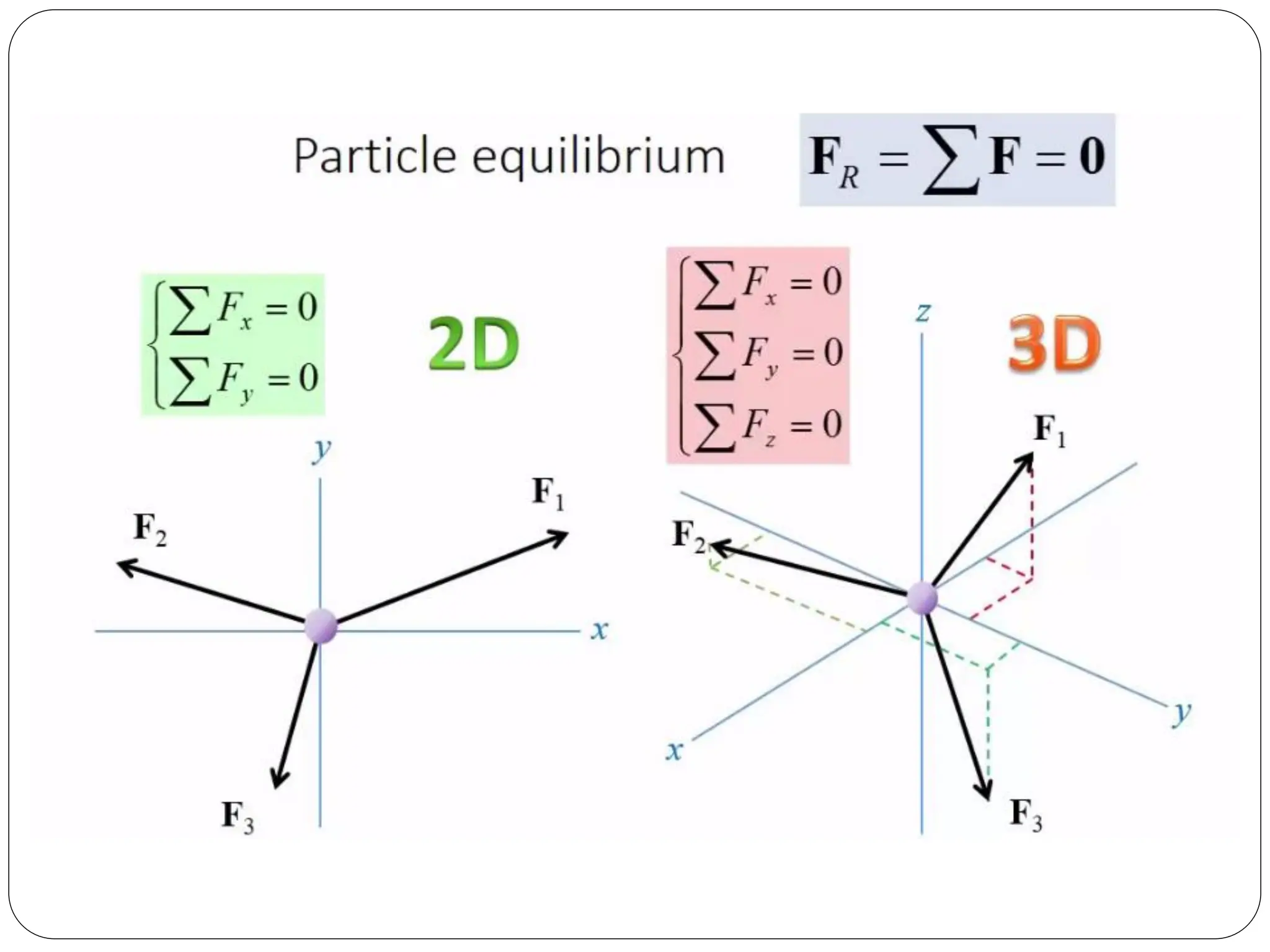
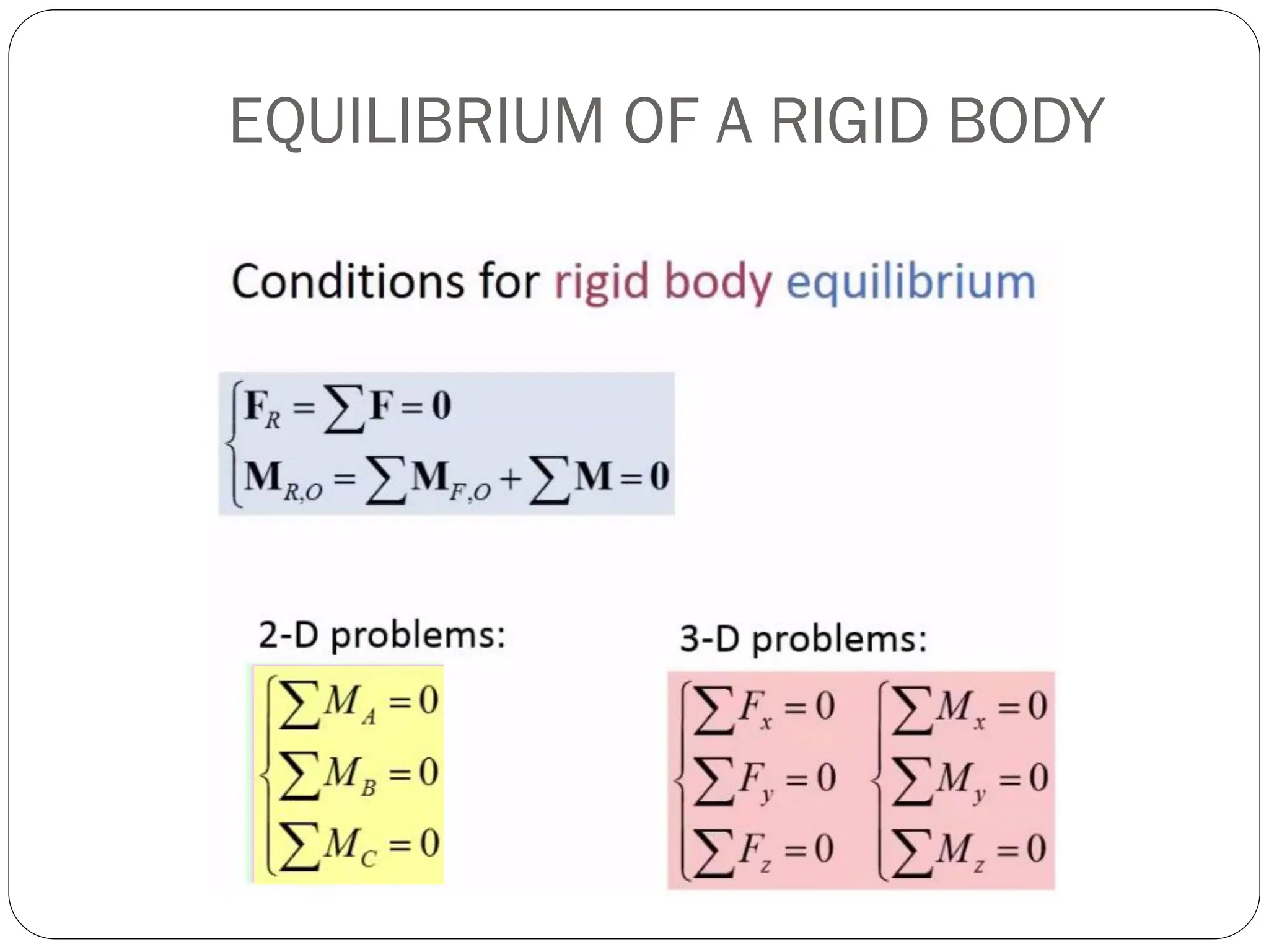
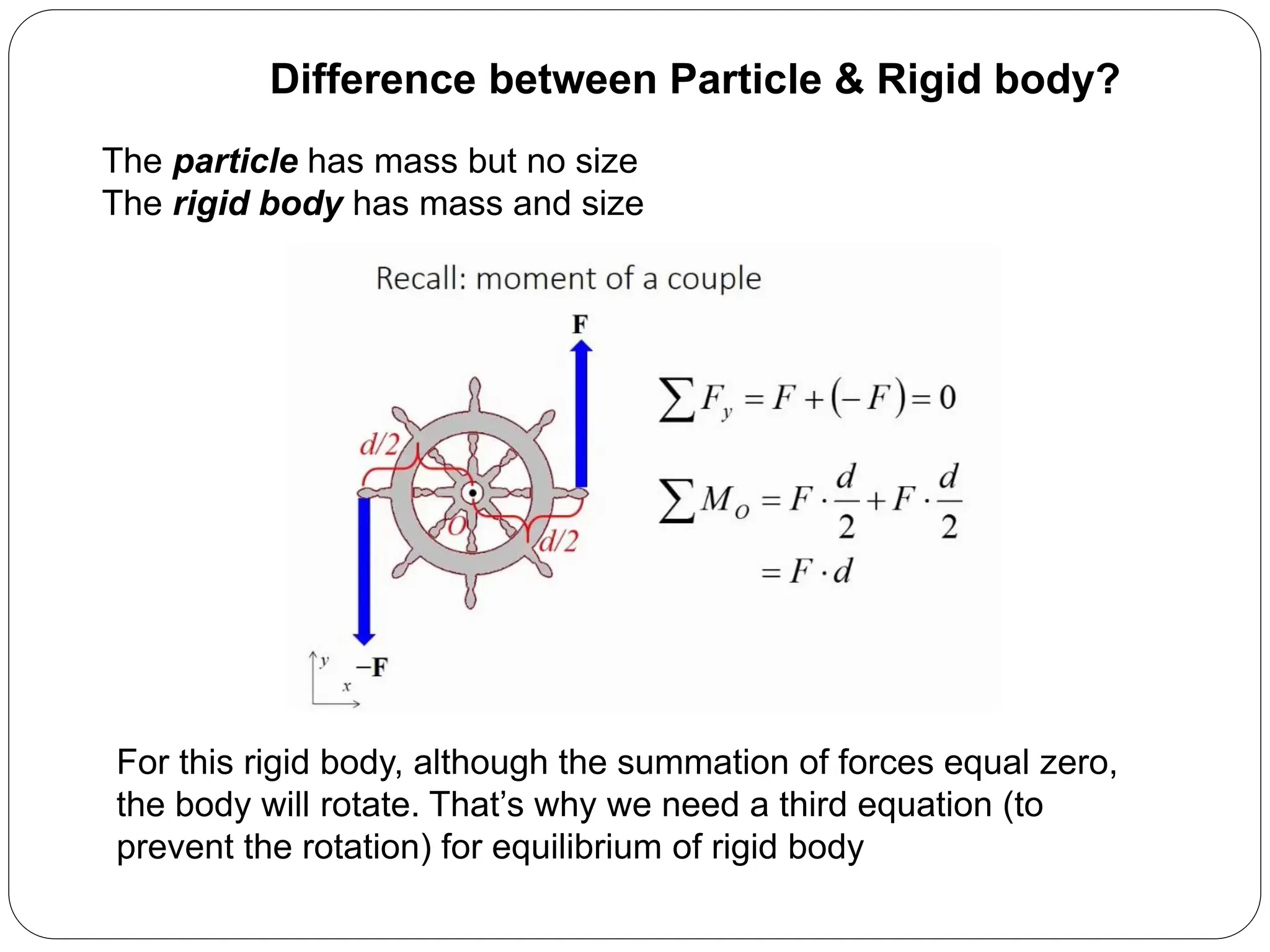
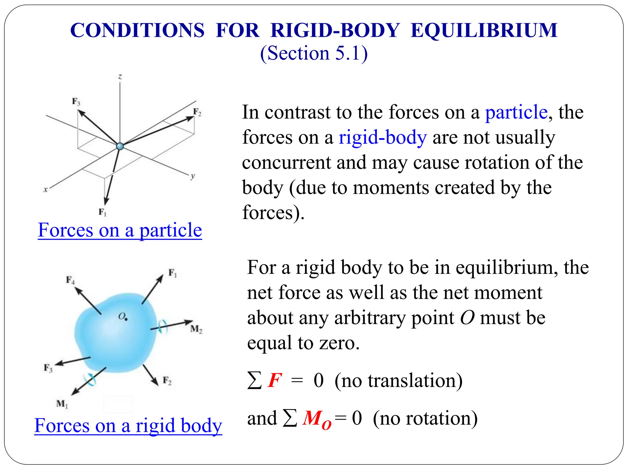
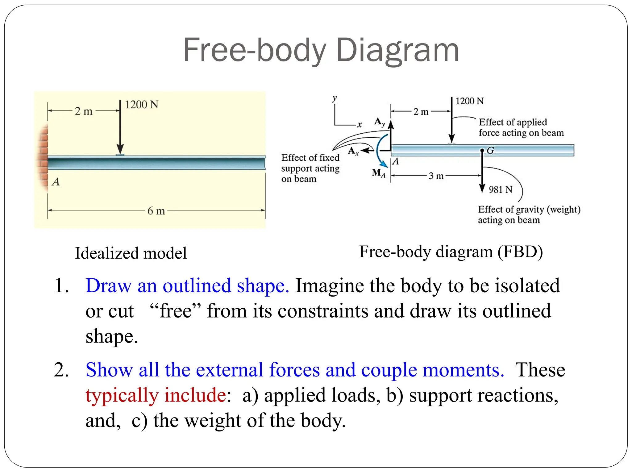
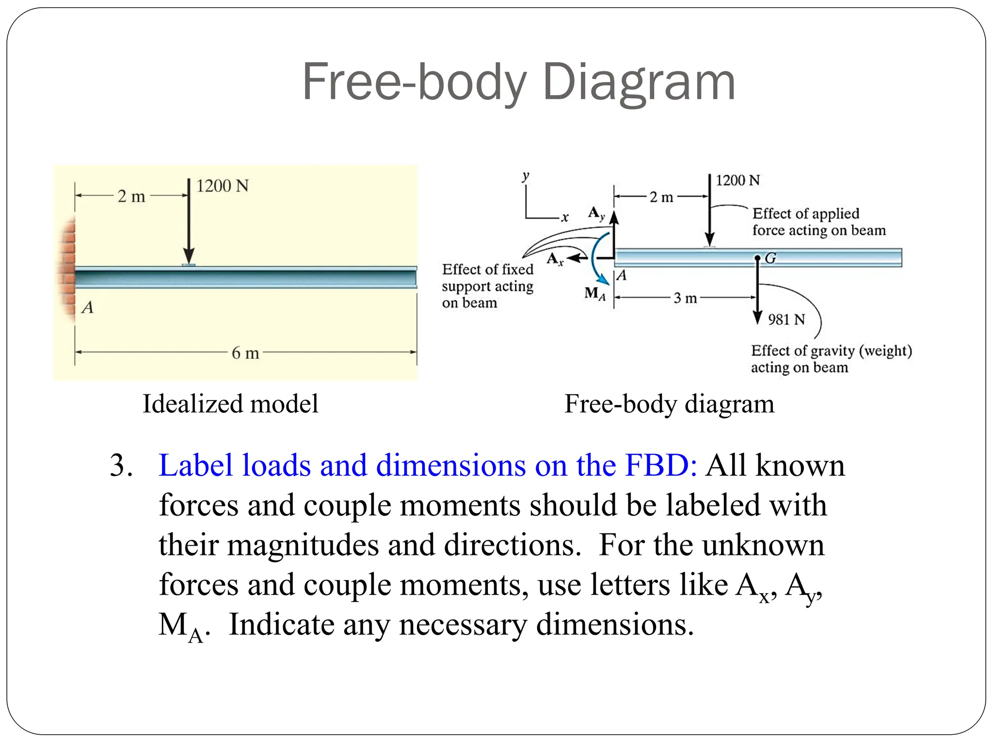
Introduction to conditions for rigid body equilibrium, free body diagrams, and the differences between particles and rigid bodies.
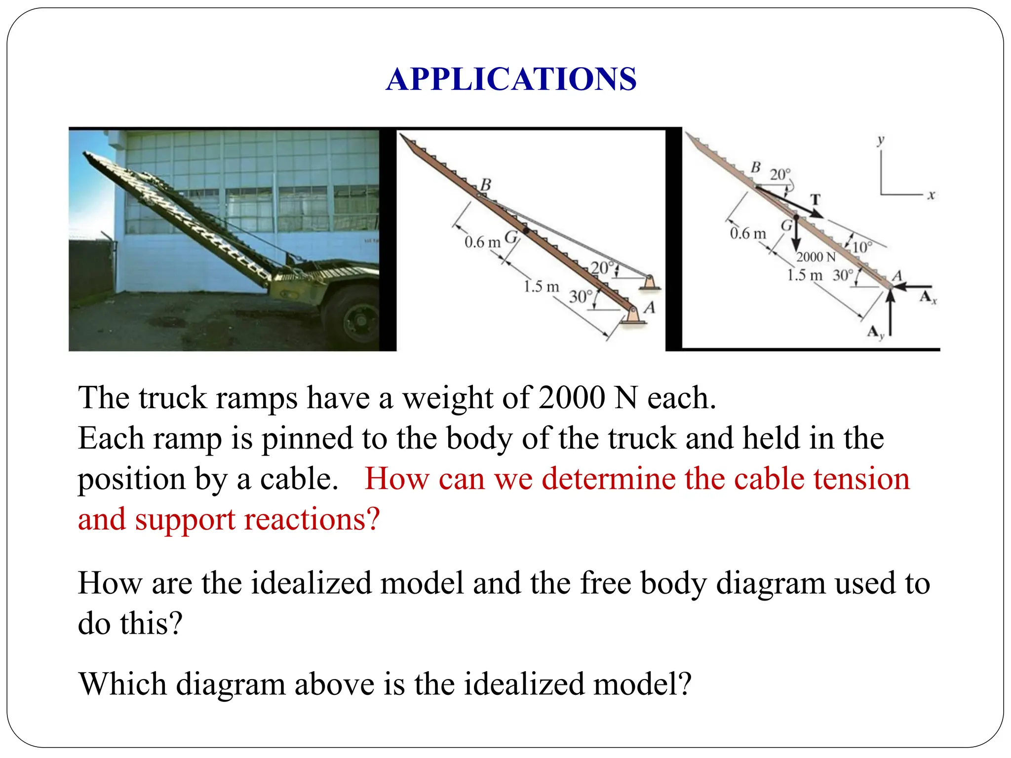
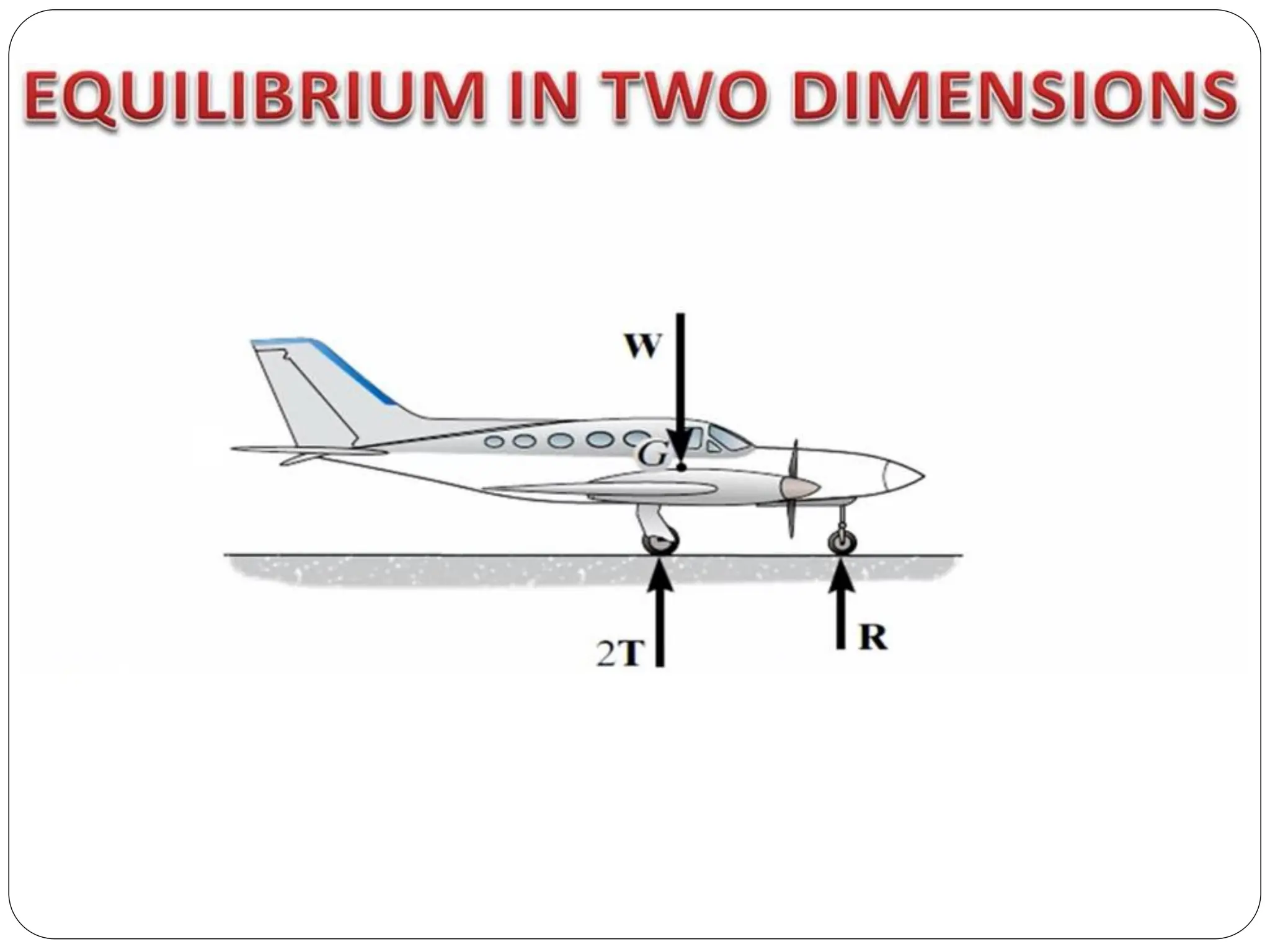
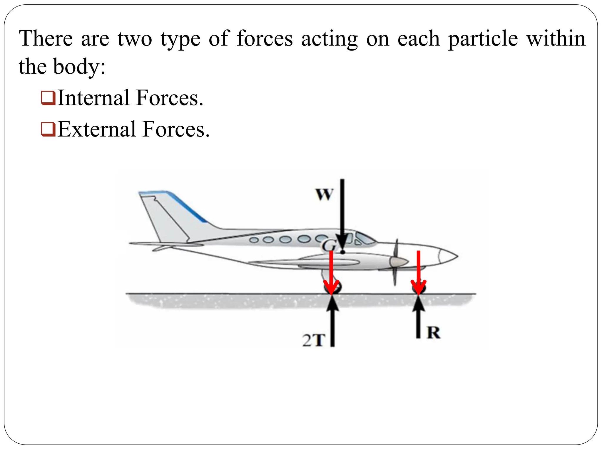
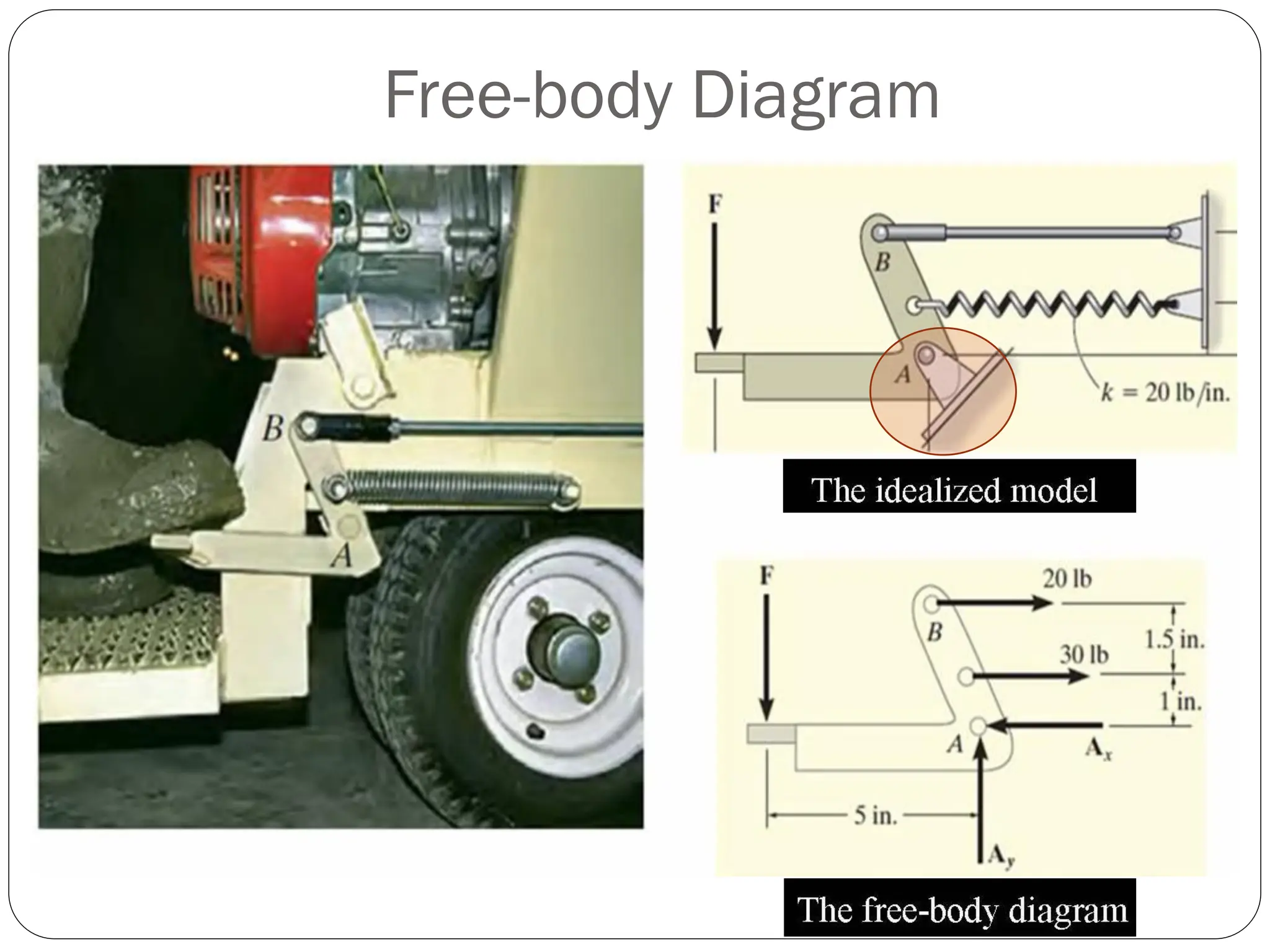
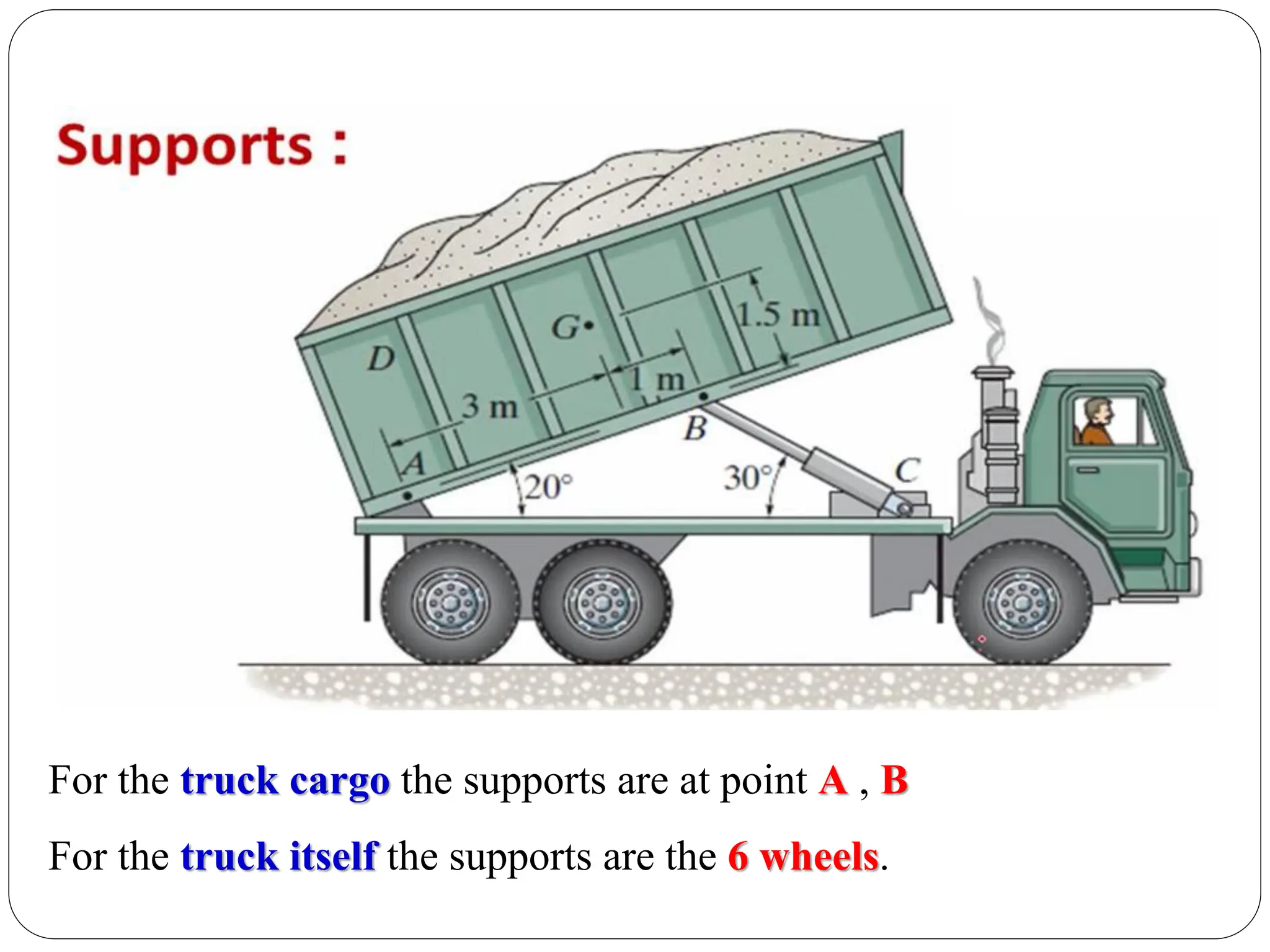
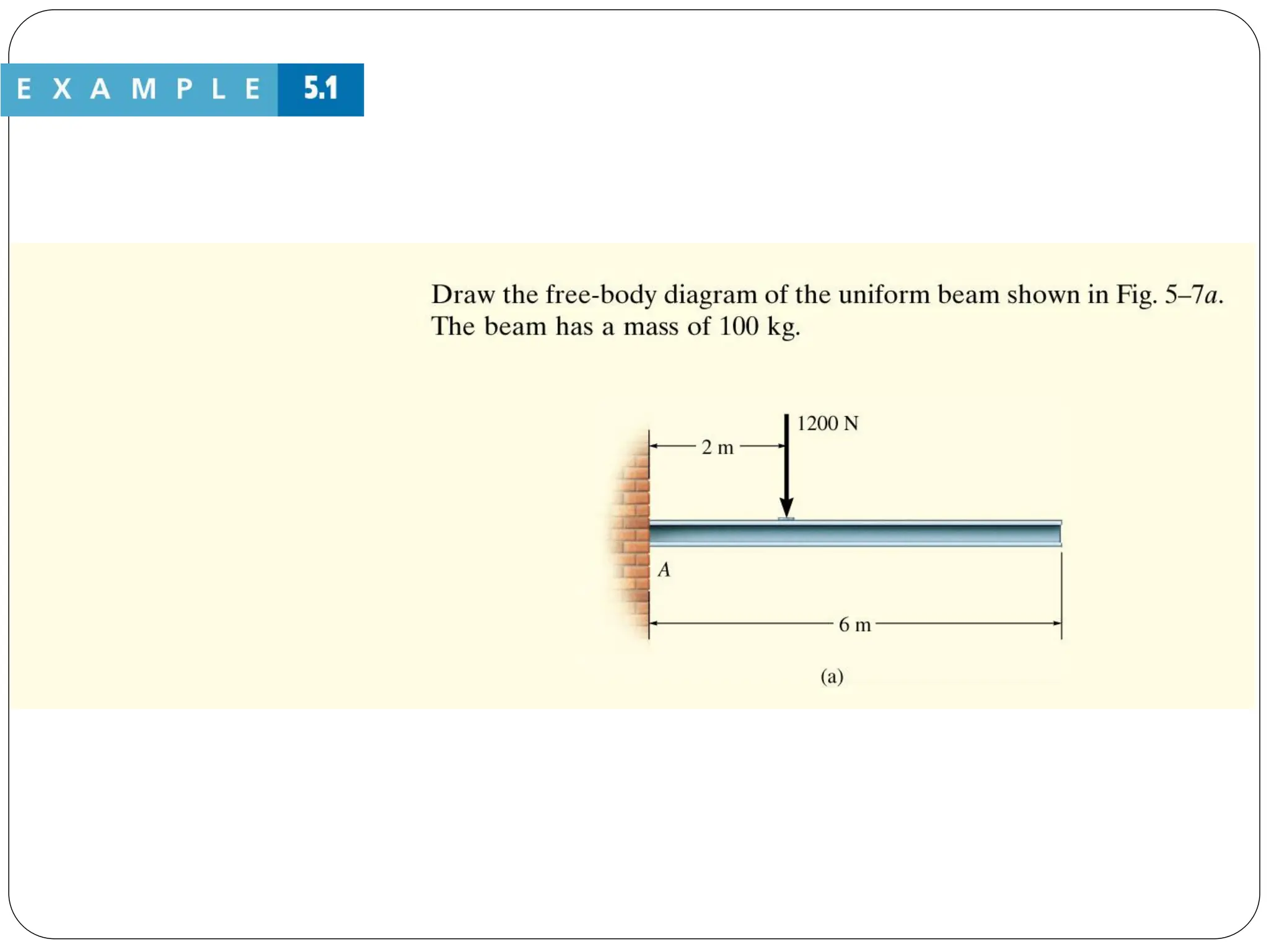
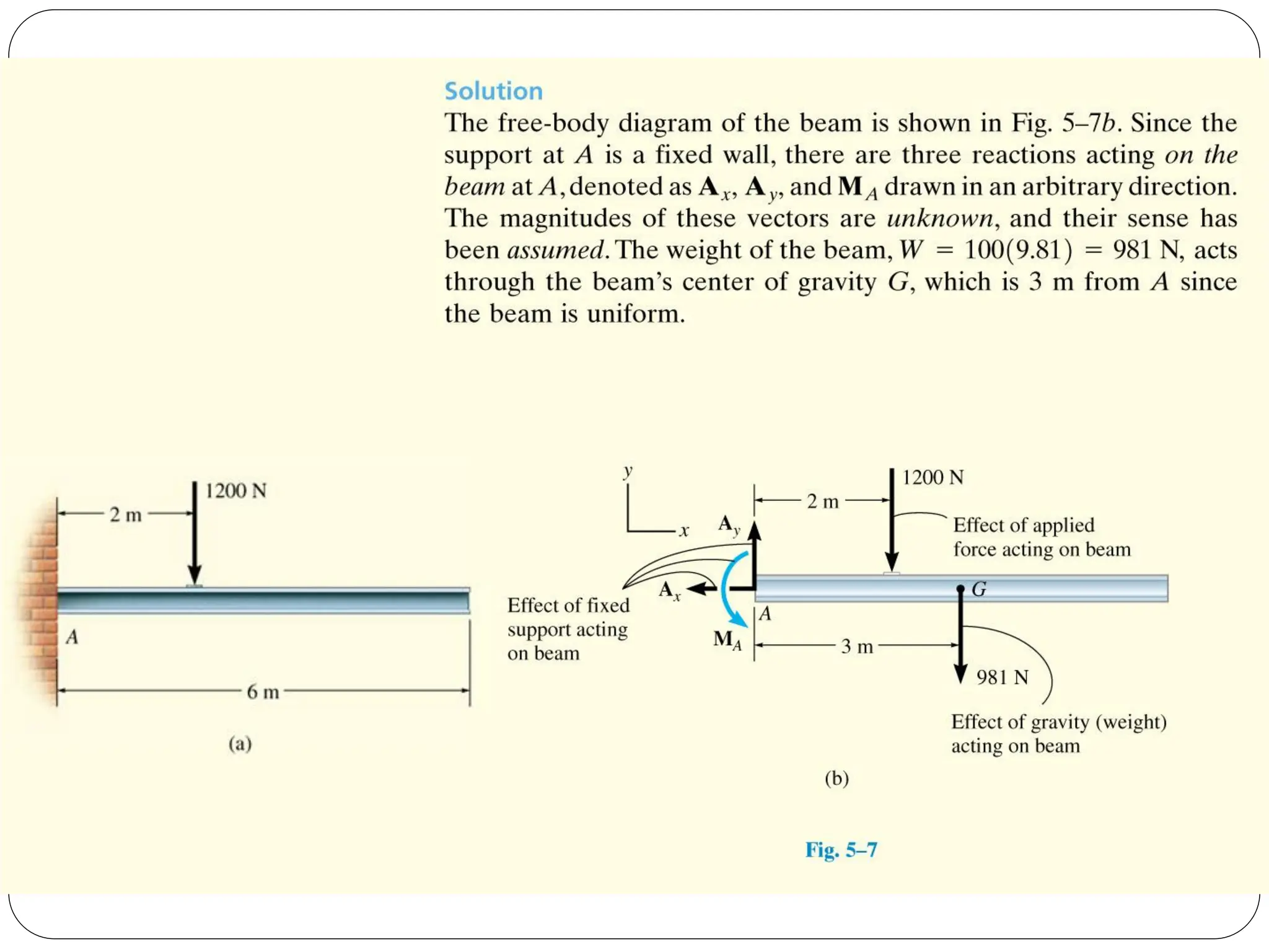
Application of the free body diagram to truck ramps, types of forces acting on a rigid body.
Introduction to conditions for rigid body equilibrium, free body diagrams, and the differences between particles and rigid bodies.
Application of the free body diagram to truck ramps, types of forces acting on a rigid body.
Application of the free body diagram to truck ramps, types of forces acting on a rigid body.
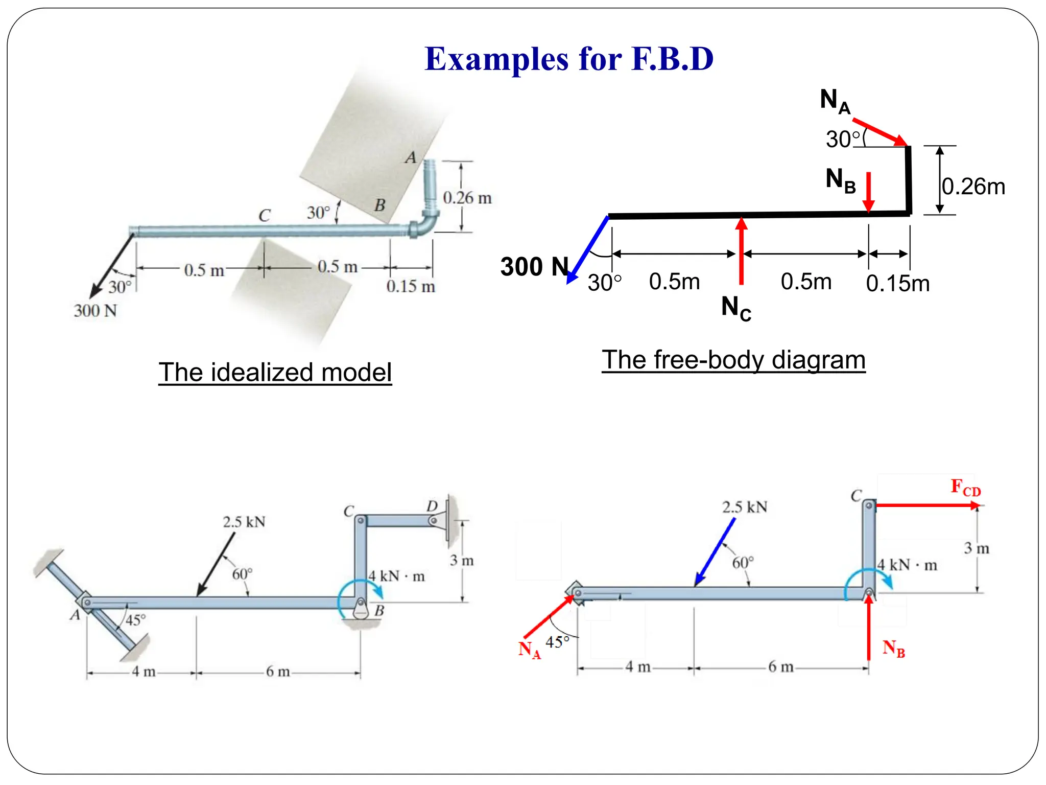
Steps to create effective free-body diagrams including labeling forces and dimensions.
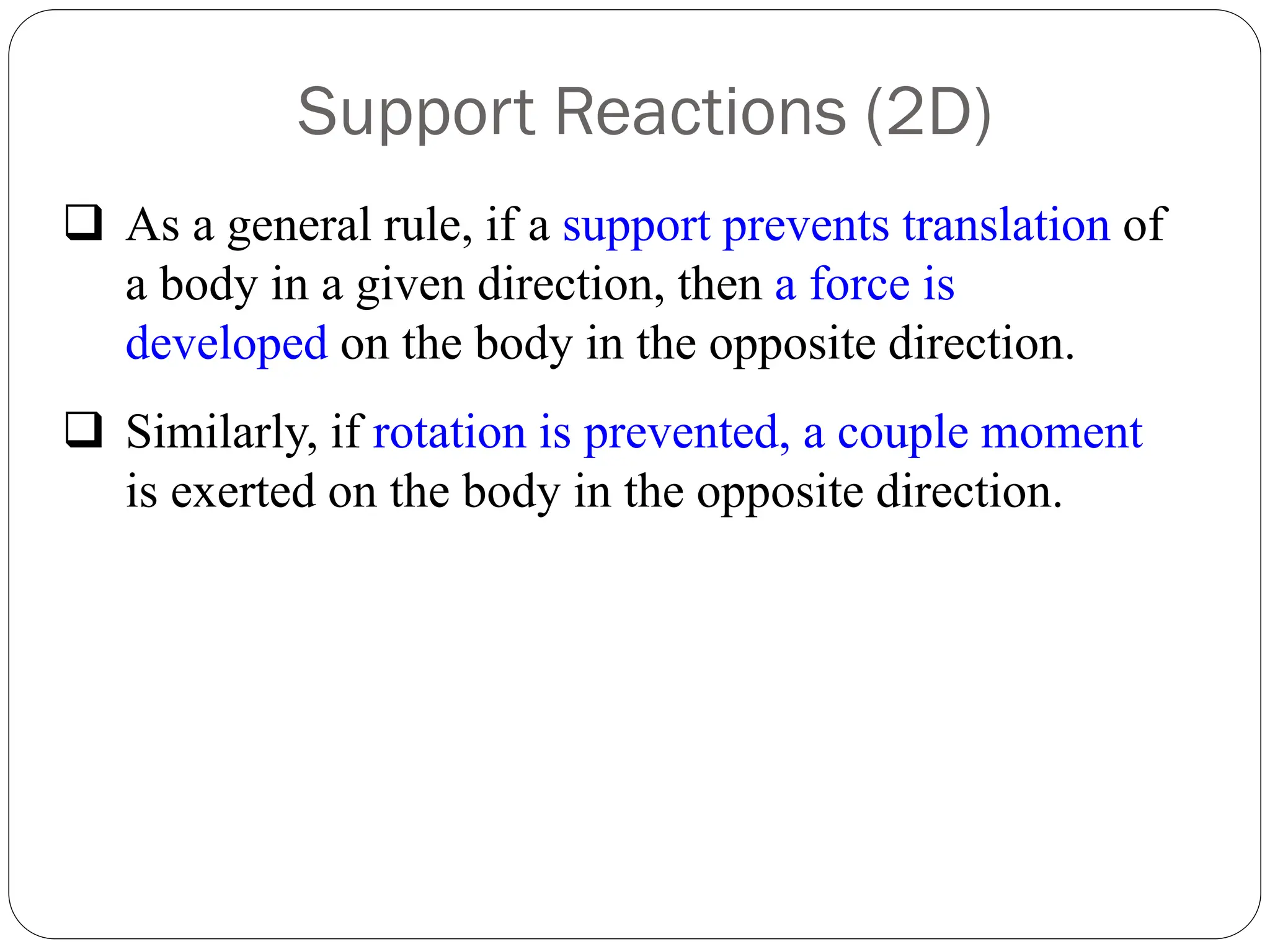
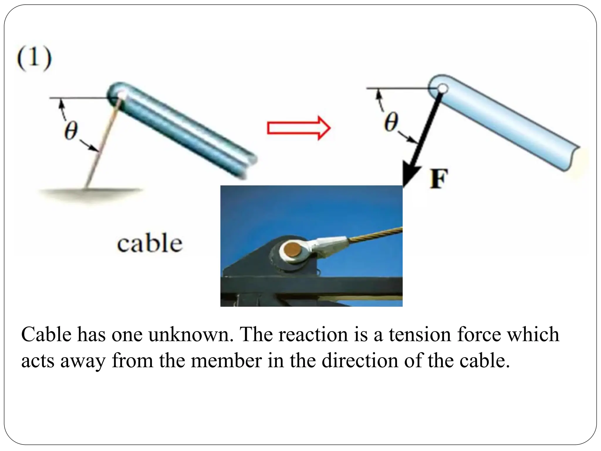
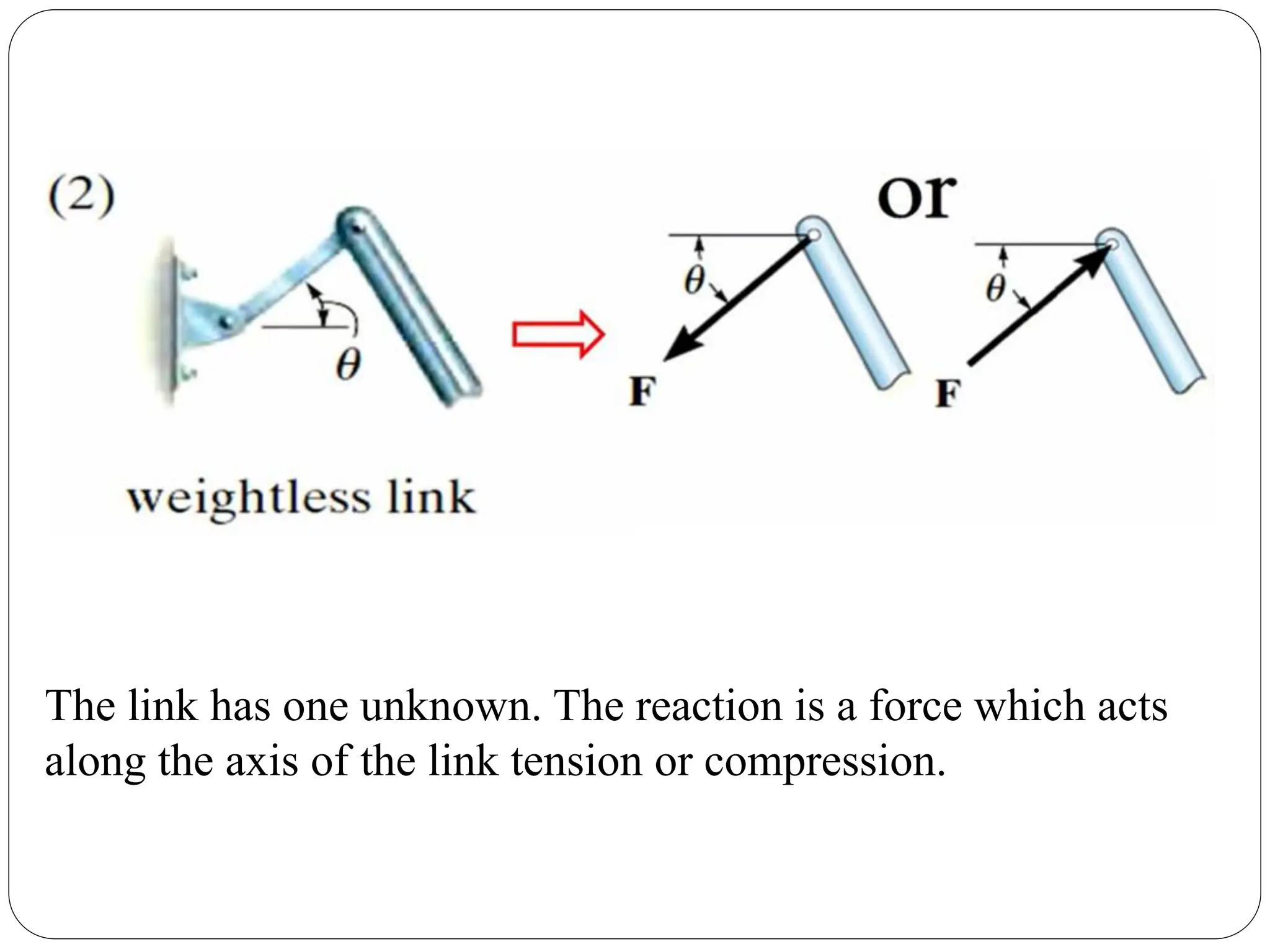
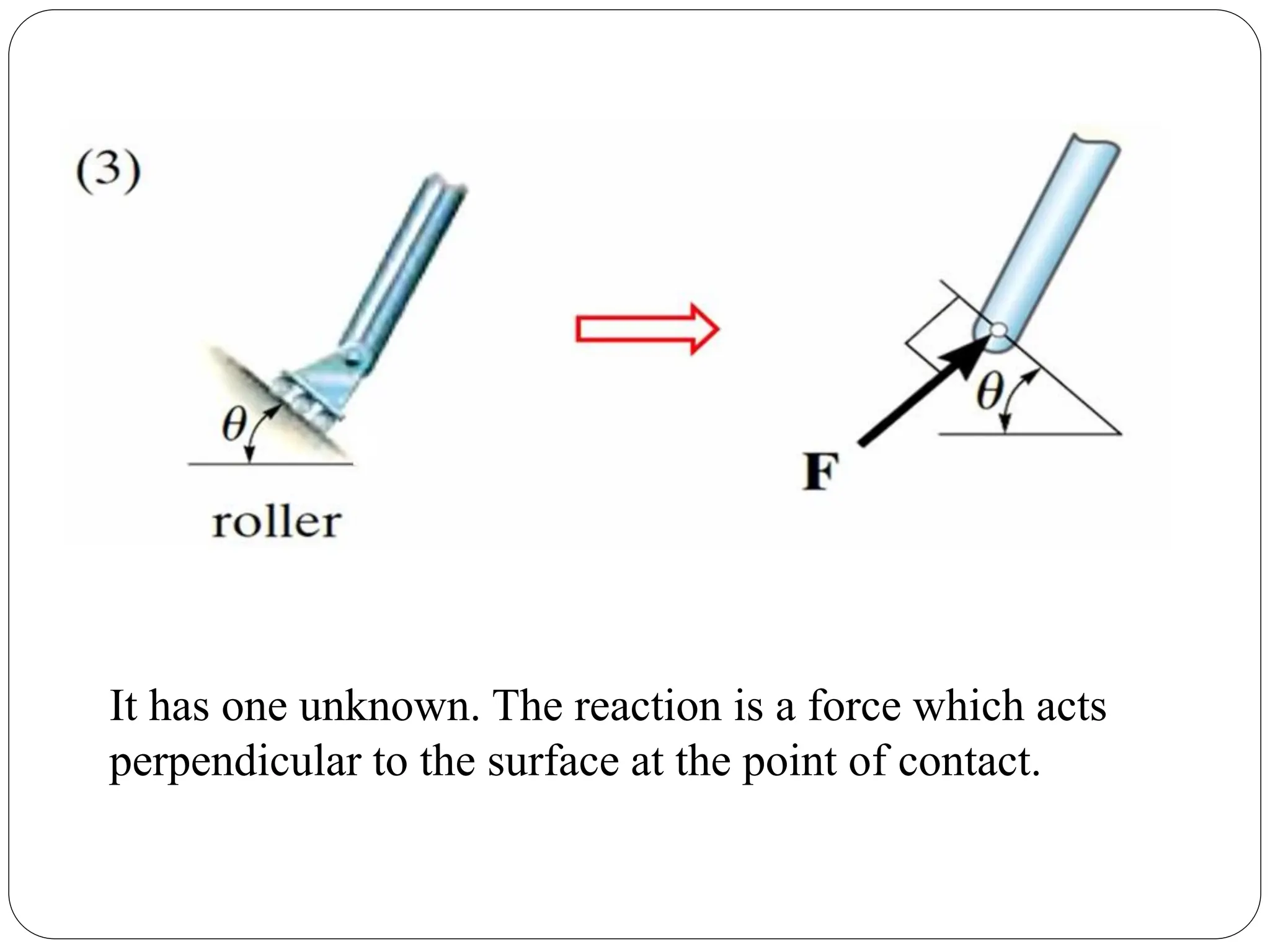
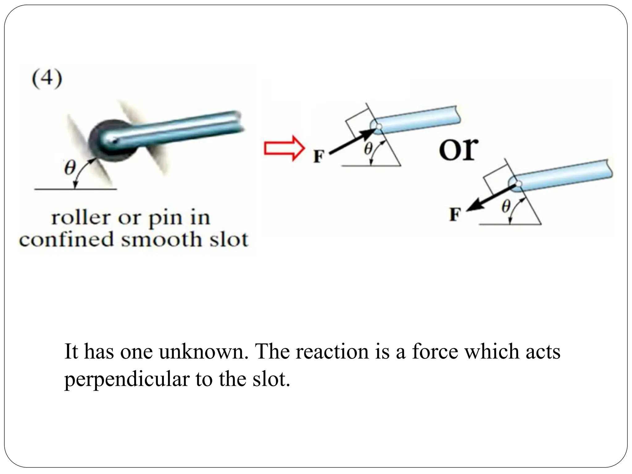
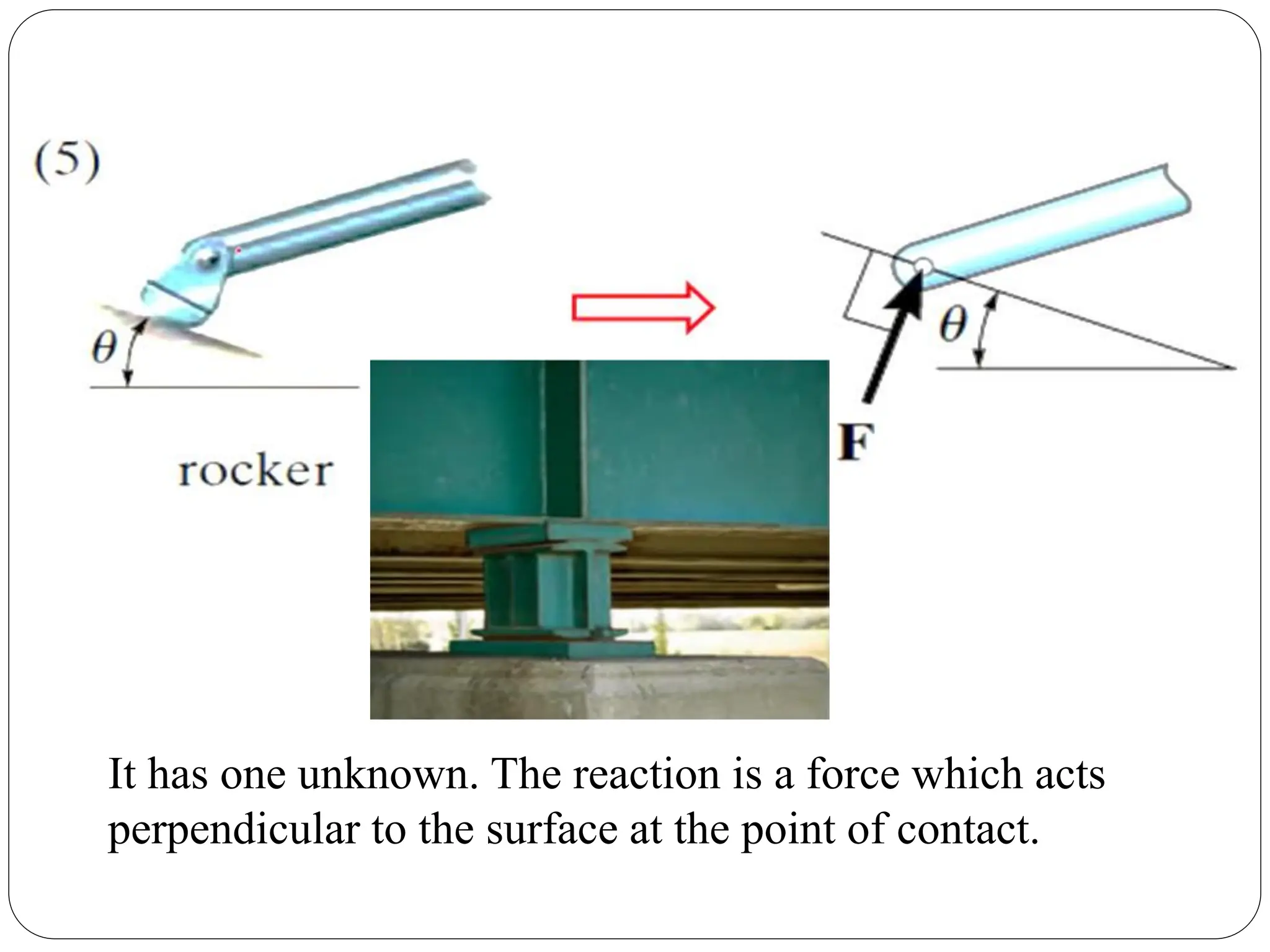
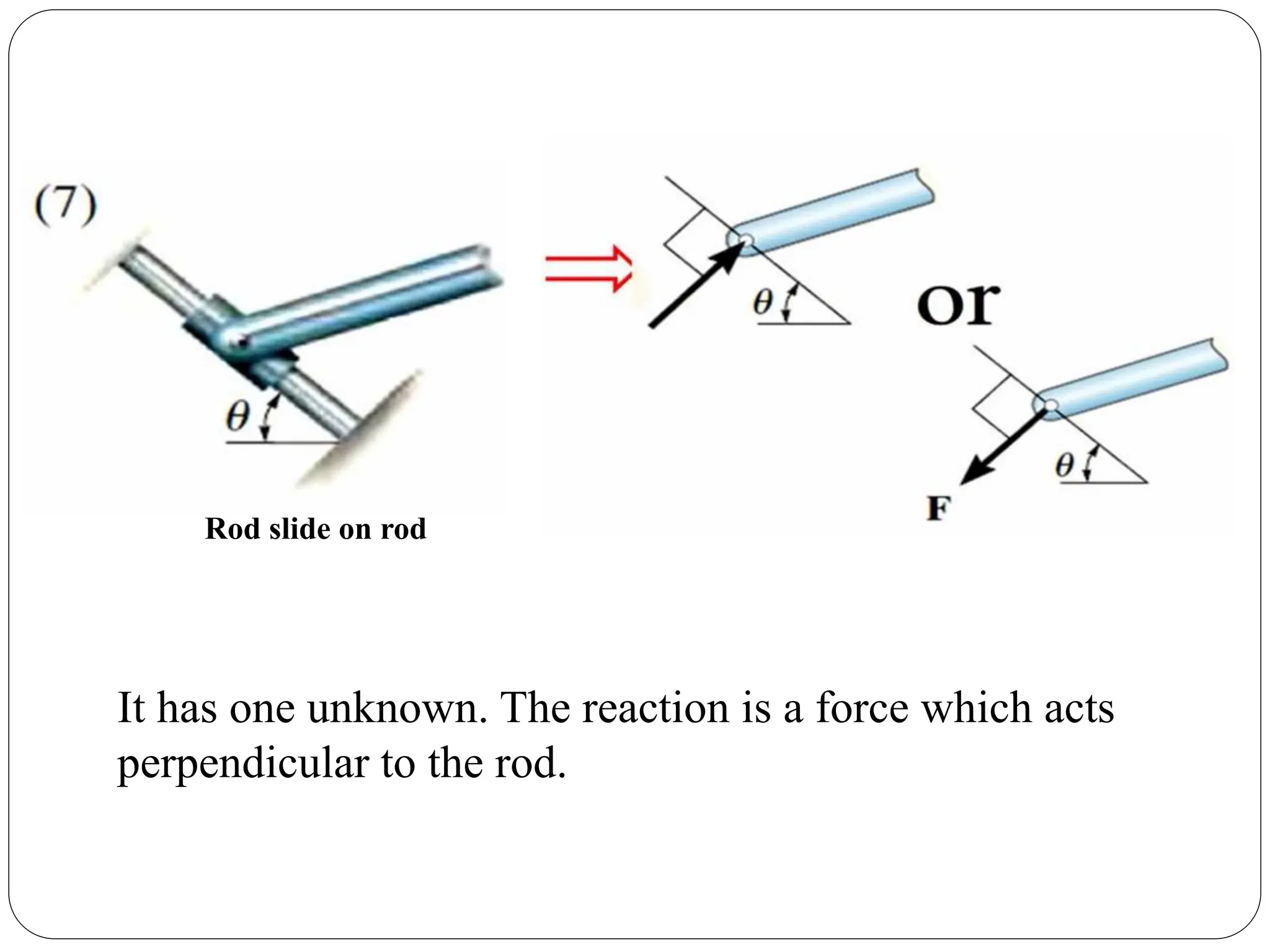
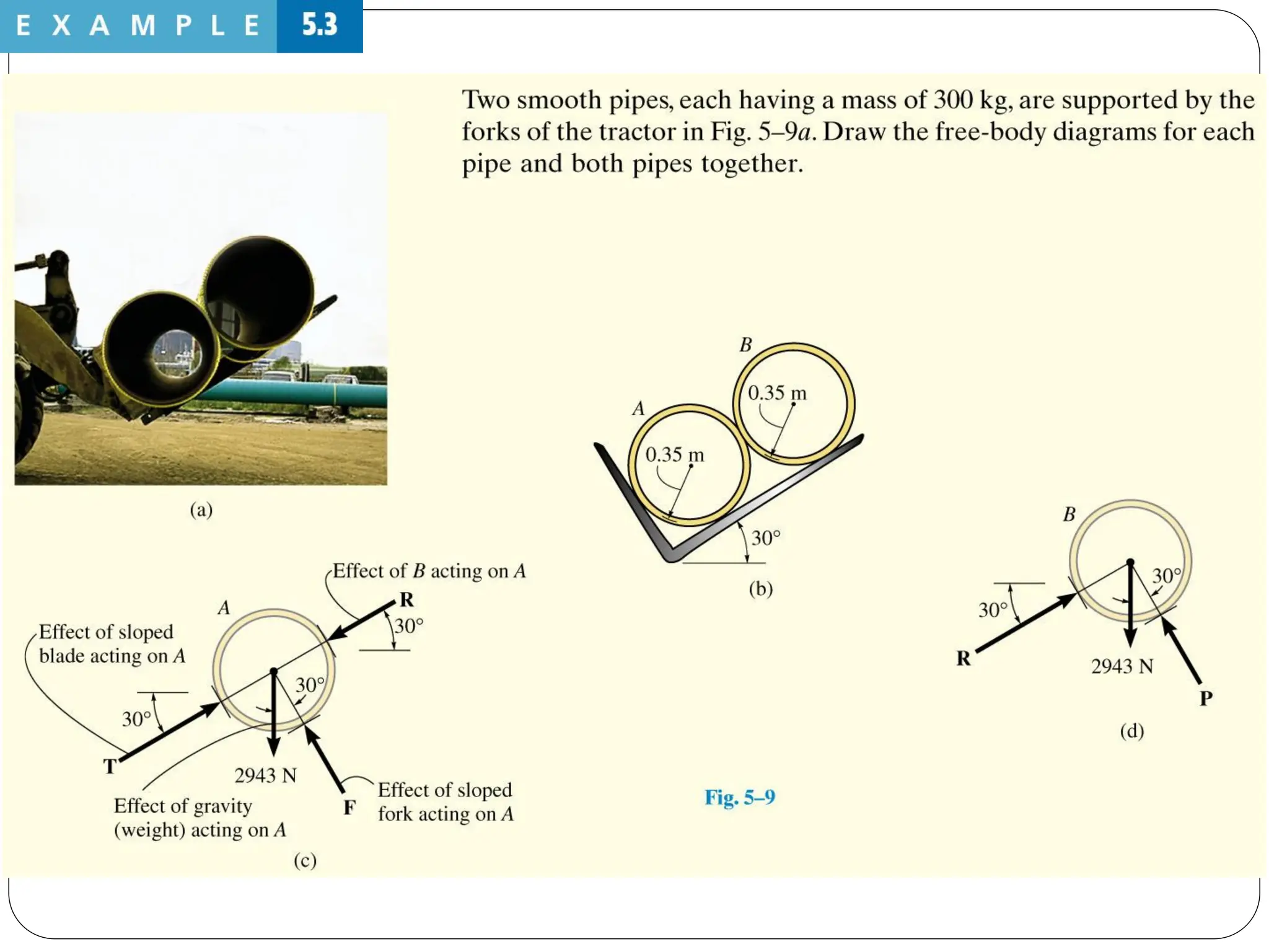
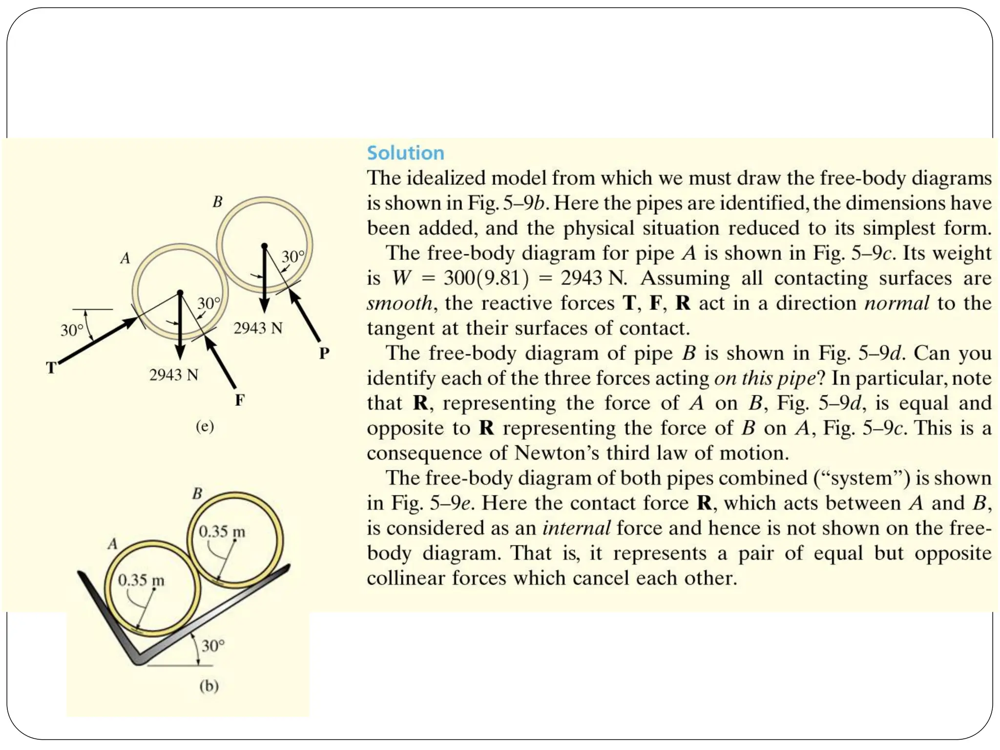
Analysis of various support reactions on rigid bodies with different internal and external forces.
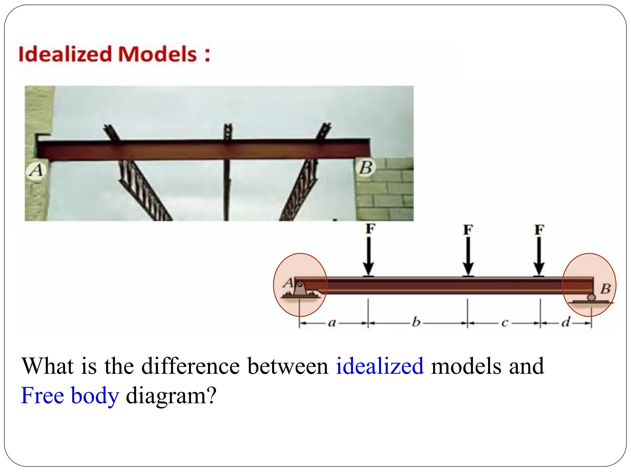
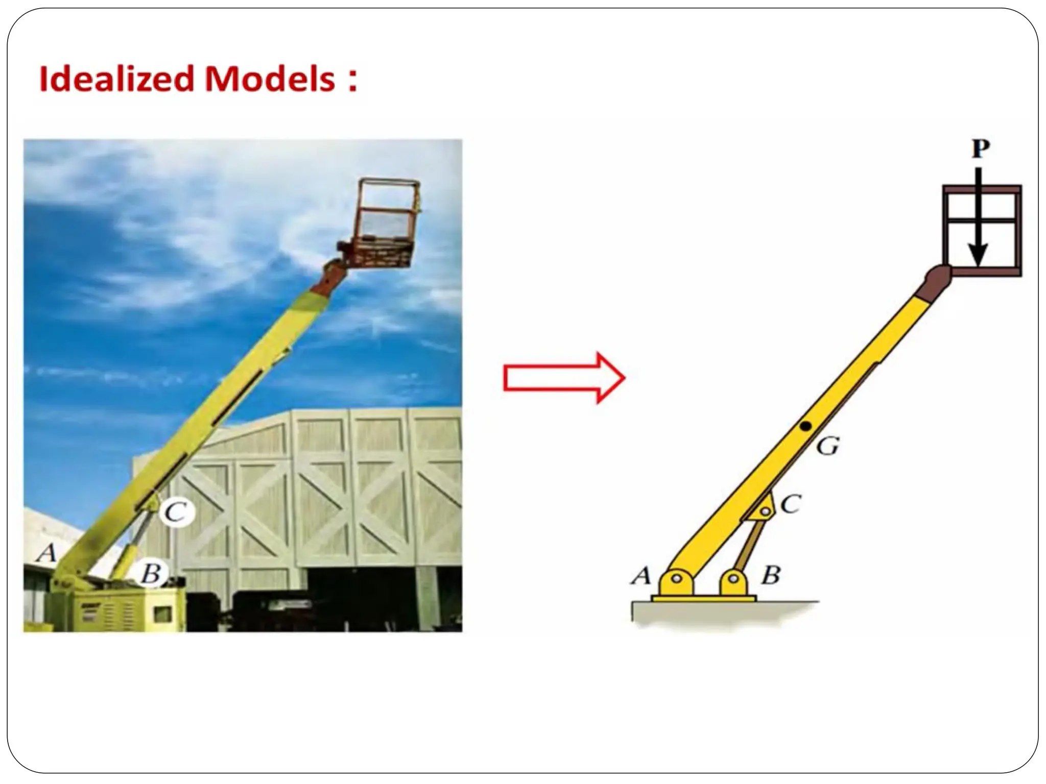
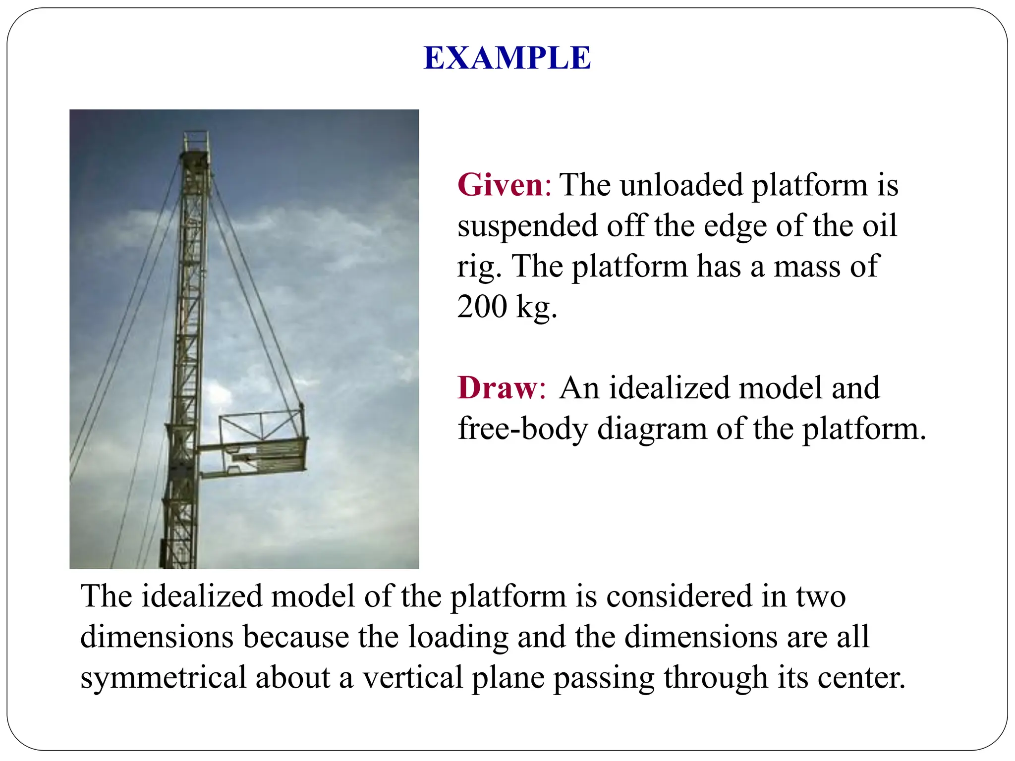
Understanding the difference between idealized models and free body diagrams with examples.
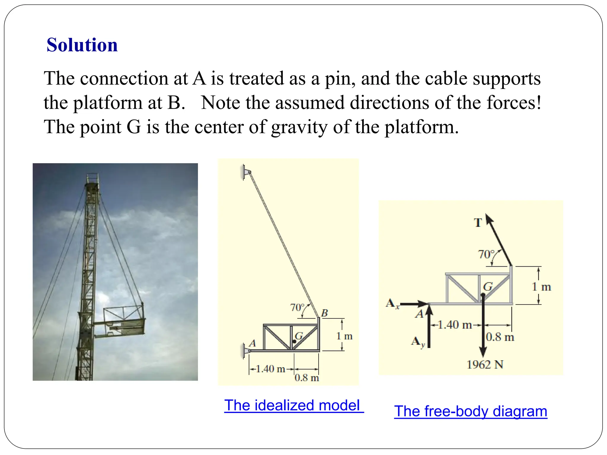
Understanding the difference between idealized models and free body diagrams with examples.
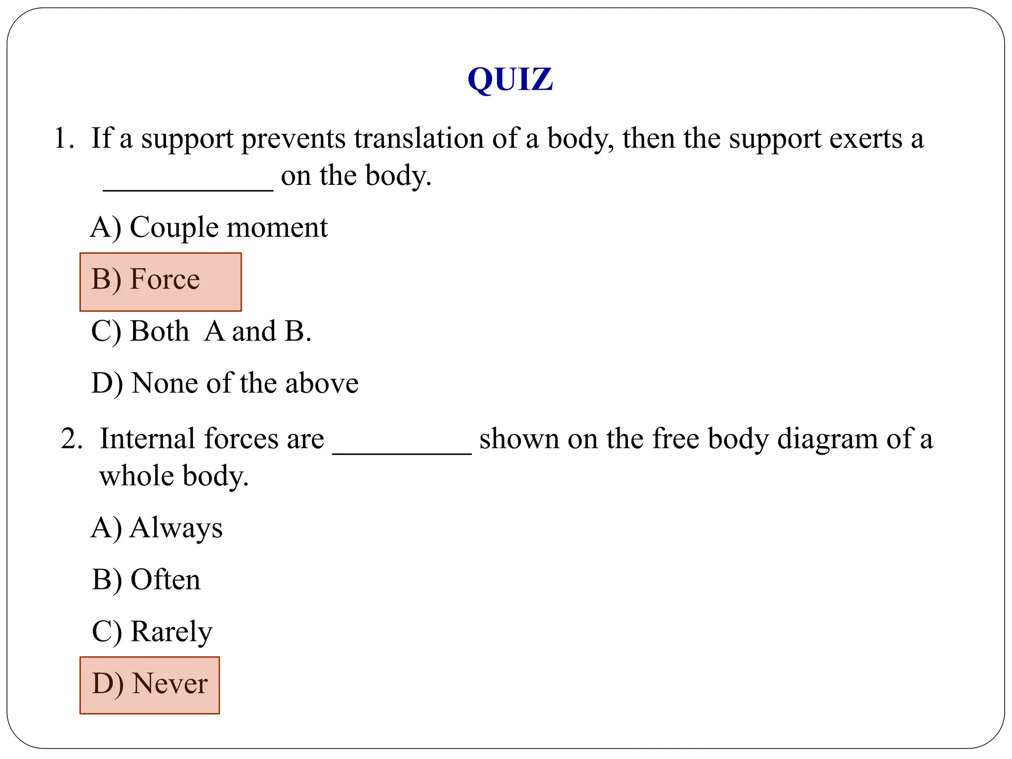
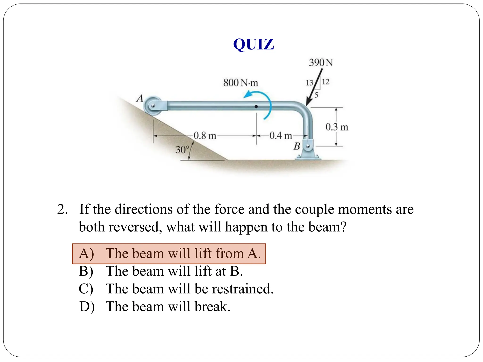
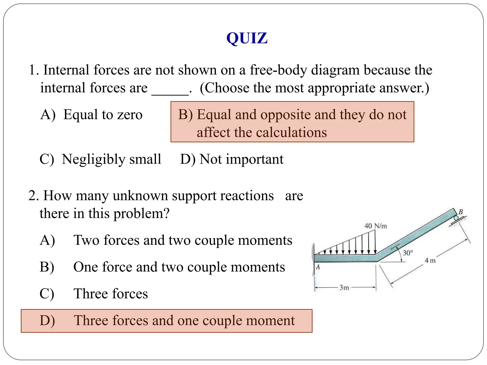
Questions aimed at assessing understanding of concepts related to forces, reactions and free-body diagrams.


