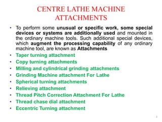
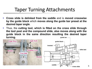
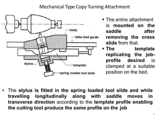
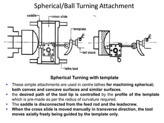
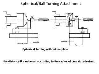
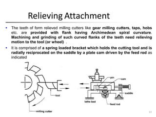
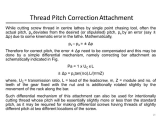
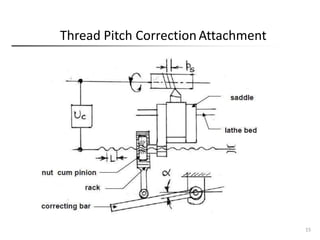
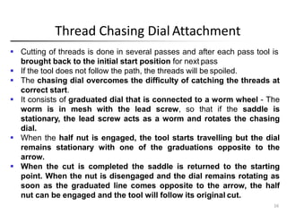
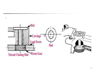
SPECIAL ATTACHMENTS FOR
LATHE
CENTRE LATHE MACHINE
ATTACHMENTS
2
• To perform some unusual or specific work, some special
devices or systems are additionally used and mounted in
the ordinary machine tools. Such additional special devices,
which augment the processing capability of any ordinary
machine tool, are known as Attachments
• Taper turning attachment
• Copy turning attachments
• Milling and cylindrical grinding attachments
• Grinding Machine attachment For Lathe
• Spherical turning attachments
• Relieving attachment
• Thread Pitch Correction Attachment For Lathe
• Thread chase dial attachment
• Eccentric Turning attachment
Taper Turning Attachments
 Cross slide is delinked from the saddle and is moved crosswise
by the guide block which moves along the guide bar preset at the
desired taper angle.
 Thus, the cutting tool, which is fitted on the cross slide through
the tool post and the compound slide, also moves along with the
guide block in the same direction resulting the desired taper
turning.
115
Mechanical Type Copy Turning Attachment
 The entire attachment
4
is mounted on the
after
cross
saddle
removing the
slide from that.
 The
replicating
template
the job-
profile desired is
clamped at a suitable
position on the bed.
 The stylus is fitted in the spring loaded tool slide and while
travelling longitudinally along with saddle moves in
transverse direction according to the template profile enabling
the cutting tool produce the same profile on the job
Hydraulic type Copy Turning Attachment
5
 In mechanical system the heavy cutting force is
transmitted at the tip of the stylus, which causes
vibration, large friction and faster wear and tear.
 In hydraulic copying, where the stylus works simply as
a valve – spool against a light spring and is not
affected by the cutting force.
 Here also, the stylus moves along the template
profile to replicate it on the job.
 Costlier than the mechanical type but works much
smoothly and accurately.
Hydraulic Type Copy Turning Attachment
118
 The cutting tool is rigidly
fixed on the cross slide
which also acts as a valve –
cum – cylinder.
 If stylus remains on a
straight edge parallel to the
lathe bed, the cylinder does
not move transversely and
the tool causes straight
turning.
 If stylus starts moving along a slope or profile, i.e., in cross feed
direction the ports open and the cylinder starts moving accordingly
against the piston fixed on the saddle.
 Again the movement of the cylinder i.e., the slide holding the tool,
is by same amount travelled by the stylus, which closes the ports.
 Repeating of such quick incremental movements of the tool, Δx and Δy
result in the profile with little surface roughness.
Milling Attachment
This is a milling head,
comprising a motor, a small
gear box and a spindle to
hold the milling cutter,
mounted on the saddle after
removing the cross slide etc.
are
Milling attachments
generally used for making
flat surfaces, straight and
helical grooves,
long and deep
splines,
screw
threads, worms etc. in centre
lathes by using suitable milling
cutters.
7
Grinding
Attachment
 Similar to milling attachment, but no gear box and the spindle speed is
much higher as needed for grinding operation.
 Employed for external and internal cylindrical grinding, finishing
grooves, splines etc. And also for finish grinding of screw threads in
centre lathe.
 Cannot provide high accuracy and finish.
 Called tool post grinder.
 It is mounted on the compound rest in place of tool post.
 Consists of a base plate, grinding wheel and a motor.
 The job is held in a chuck or between centres.
 It is extensively used for grinding lathe centres in position.
8
Spherical/Ball Turning Attachment
Spherical Turning with template
 These simple attachments are used in centre lathes for machining spherical;
both convex and concave surfaces and similar surfaces.
 the desired path of the tool tip is controlled by the profile of the template
which is pre-made as per the radius of curvature required.
 The saddle is disconnected from the feed rod and the leadscrew.
 When the cross slide is moved manually in transverse direction, the tool
moves axially freely being guided by the template only.
Spherical/Ball Turning Attachment
the distance R can be set according to the radius of curvaturedesired.
Spherical Turning without template
Relieving Attachment
 The teeth of form relieved milling cutters like gear milling cutters, taps, hobs
etc. are provided with flank having Archimedean spiral curvature.
Machining and grinding of such curved flanks of the teeth need relieving
motion to the tool (or wheel) .
 It is comprised of a spring loaded bracket which holds the cutting tool and is
radially reciprocated on the saddle by a plate cam driven by the feed rod as
indicated
13
Thread Pitch CorrectionAttachment
14
While cutting screw thread in centre lathes by single point chasing tool, often the
actual pitch, pa deviates from the desired (or stipulated) pitch, ps by an error (say ±
Δp) due to some kinematic error in the lathe. Mathematically,
ps – pa = ± Δp
Therefore for correct pitch, the error ± Δp need to be compensated and this may be
done by a simple differential mechanism, namely correcting bar attachment as
schematically indicated in Fig.
Pa = 1 x UC x L
± Δp = pstan(±α).L/(πmZ)
where, UC = transmission ratio, L = lead of the leadscrew, m, Z = module and no. of
teeth of the gear fixed with the nut and is additionally rotated slightly by the
movement of the rack along the bar.
Such differential mechanism of this attachment can also be used for intentionally
cutting thread whose pitch will be essentially slightly more or less than the standard
pitch, as it may be required for making differential screws having threads of slightly
different pitch at two different locations of the screw.
Thread Pitch CorrectionAttachment
15
Thread Chasing Dial Attachment
16
 Cutting of threads is done in several passes and after each pass tool is
brought back to the initial start position for next pass
 If the tool does not follow the path, the threads will be spoiled.
 The chasing dial overcomes the difficulty of catching the threads at
correct start.
 It consists of graduated dial that is connected to a worm wheel - The
worm is in mesh with the lead screw, so that if the saddle is
stationary, the lead screw acts as a worm and rotates the chasing
dial.
 When the half nut is engaged, the tool starts travelling but the dial
remains stationary with one of the graduations opposite to the
arrow.
 When the cut is completed the saddle is returned to the starting
point. When the nut is disengaged and the dial remains rotating as
soon as the graduated line comes opposite to the arrow, the half
nut can be engaged and the tool will follow its original cut.
Thread Chasing Dial Attachment
.
17
Eccentric Turning Attachment
18
.
 It refers to the turning of certain diameters at different
lengths on the same shaft or jobs whose axis is not falling
in line with the main axis. A crank shaft of an engine is the
example of such job.
 This type of attachment is equipped with the provision of shifting
the centres of the work away from the lathe spindle axis.
 An accurate marking and truing is of prime important in the
sequence of operation of jobs of this nature.

MT-II UNIT II TURNING

  • 1.
  • 2.
    CENTRE LATHE MACHINE ATTACHMENTS 2 •To perform some unusual or specific work, some special devices or systems are additionally used and mounted in the ordinary machine tools. Such additional special devices, which augment the processing capability of any ordinary machine tool, are known as Attachments • Taper turning attachment • Copy turning attachments • Milling and cylindrical grinding attachments • Grinding Machine attachment For Lathe • Spherical turning attachments • Relieving attachment • Thread Pitch Correction Attachment For Lathe • Thread chase dial attachment • Eccentric Turning attachment
  • 3.
    Taper Turning Attachments Cross slide is delinked from the saddle and is moved crosswise by the guide block which moves along the guide bar preset at the desired taper angle.  Thus, the cutting tool, which is fitted on the cross slide through the tool post and the compound slide, also moves along with the guide block in the same direction resulting the desired taper turning. 115
  • 4.
    Mechanical Type CopyTurning Attachment  The entire attachment 4 is mounted on the after cross saddle removing the slide from that.  The replicating template the job- profile desired is clamped at a suitable position on the bed.  The stylus is fitted in the spring loaded tool slide and while travelling longitudinally along with saddle moves in transverse direction according to the template profile enabling the cutting tool produce the same profile on the job
  • 5.
    Hydraulic type CopyTurning Attachment 5  In mechanical system the heavy cutting force is transmitted at the tip of the stylus, which causes vibration, large friction and faster wear and tear.  In hydraulic copying, where the stylus works simply as a valve – spool against a light spring and is not affected by the cutting force.  Here also, the stylus moves along the template profile to replicate it on the job.  Costlier than the mechanical type but works much smoothly and accurately.
  • 6.
    Hydraulic Type CopyTurning Attachment 118  The cutting tool is rigidly fixed on the cross slide which also acts as a valve – cum – cylinder.  If stylus remains on a straight edge parallel to the lathe bed, the cylinder does not move transversely and the tool causes straight turning.  If stylus starts moving along a slope or profile, i.e., in cross feed direction the ports open and the cylinder starts moving accordingly against the piston fixed on the saddle.  Again the movement of the cylinder i.e., the slide holding the tool, is by same amount travelled by the stylus, which closes the ports.  Repeating of such quick incremental movements of the tool, Δx and Δy result in the profile with little surface roughness.
  • 7.
    Milling Attachment This isa milling head, comprising a motor, a small gear box and a spindle to hold the milling cutter, mounted on the saddle after removing the cross slide etc. are Milling attachments generally used for making flat surfaces, straight and helical grooves, long and deep splines, screw threads, worms etc. in centre lathes by using suitable milling cutters. 7
  • 8.
    Grinding Attachment  Similar tomilling attachment, but no gear box and the spindle speed is much higher as needed for grinding operation.  Employed for external and internal cylindrical grinding, finishing grooves, splines etc. And also for finish grinding of screw threads in centre lathe.  Cannot provide high accuracy and finish.  Called tool post grinder.  It is mounted on the compound rest in place of tool post.  Consists of a base plate, grinding wheel and a motor.  The job is held in a chuck or between centres.  It is extensively used for grinding lathe centres in position. 8
  • 9.
    Spherical/Ball Turning Attachment SphericalTurning with template  These simple attachments are used in centre lathes for machining spherical; both convex and concave surfaces and similar surfaces.  the desired path of the tool tip is controlled by the profile of the template which is pre-made as per the radius of curvature required.  The saddle is disconnected from the feed rod and the leadscrew.  When the cross slide is moved manually in transverse direction, the tool moves axially freely being guided by the template only.
  • 10.
    Spherical/Ball Turning Attachment thedistance R can be set according to the radius of curvaturedesired. Spherical Turning without template
  • 13.
    Relieving Attachment  Theteeth of form relieved milling cutters like gear milling cutters, taps, hobs etc. are provided with flank having Archimedean spiral curvature. Machining and grinding of such curved flanks of the teeth need relieving motion to the tool (or wheel) .  It is comprised of a spring loaded bracket which holds the cutting tool and is radially reciprocated on the saddle by a plate cam driven by the feed rod as indicated 13
  • 14.
    Thread Pitch CorrectionAttachment 14 Whilecutting screw thread in centre lathes by single point chasing tool, often the actual pitch, pa deviates from the desired (or stipulated) pitch, ps by an error (say ± Δp) due to some kinematic error in the lathe. Mathematically, ps – pa = ± Δp Therefore for correct pitch, the error ± Δp need to be compensated and this may be done by a simple differential mechanism, namely correcting bar attachment as schematically indicated in Fig. Pa = 1 x UC x L ± Δp = pstan(±α).L/(πmZ) where, UC = transmission ratio, L = lead of the leadscrew, m, Z = module and no. of teeth of the gear fixed with the nut and is additionally rotated slightly by the movement of the rack along the bar. Such differential mechanism of this attachment can also be used for intentionally cutting thread whose pitch will be essentially slightly more or less than the standard pitch, as it may be required for making differential screws having threads of slightly different pitch at two different locations of the screw.
  • 15.
  • 16.
    Thread Chasing DialAttachment 16  Cutting of threads is done in several passes and after each pass tool is brought back to the initial start position for next pass  If the tool does not follow the path, the threads will be spoiled.  The chasing dial overcomes the difficulty of catching the threads at correct start.  It consists of graduated dial that is connected to a worm wheel - The worm is in mesh with the lead screw, so that if the saddle is stationary, the lead screw acts as a worm and rotates the chasing dial.  When the half nut is engaged, the tool starts travelling but the dial remains stationary with one of the graduations opposite to the arrow.  When the cut is completed the saddle is returned to the starting point. When the nut is disengaged and the dial remains rotating as soon as the graduated line comes opposite to the arrow, the half nut can be engaged and the tool will follow its original cut.
  • 17.
    Thread Chasing DialAttachment . 17
  • 18.
    Eccentric Turning Attachment 18 . It refers to the turning of certain diameters at different lengths on the same shaft or jobs whose axis is not falling in line with the main axis. A crank shaft of an engine is the example of such job.  This type of attachment is equipped with the provision of shifting the centres of the work away from the lathe spindle axis.  An accurate marking and truing is of prime important in the sequence of operation of jobs of this nature.