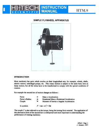
INSTRUCTION MANUAL
HTM.9 FlywheelApparatus
SIMPLE FLYWHEELAPPARATUS
INTRODUCfION
Most machineryhaspartswhich revolveon their longitudinalaxis~for example,wheels,shafts,
electricmotors,centrifugalpumps,etc. This rotary motion is subjectto the samebasiclawsas
linearmotion,but all the termshaveto be transformedto complywith the specialconditionsof
rotation.
Forexamplethesecondlaw of motionchangesasfollows:-
--~
Force
Forcex Radius
Couple
Massx Acceleration
RotationalMassx RotationalAcceleration
Momentof Inertiax AngularAcceleration
In symbols F = ma-+ C - la
ThecoupleC is alsoreferredto asthetorque,beingtheturningforceexerted.Theapplicationof
thisalternativeformof thesecondlaw is widespreadandmostimportantin underStandingthe
performanceof rotatingmachinery.
1n"M.9.PageJ.
2. October,/997.
Whereit is necessaryto startrotatingmachineryquicklythe momentof inertiamustbeassmallas
possibleto pem1itfastaccelerationwith themaximumvalueof torque. Ontheotherhand,whena
reciprocatingenginei.e.requiredto run at aunifonnspeedregardlessof thefluctuationin driving
forceaseachcylinderdeliverspowerit is commonpracticeto increasetheoverallmomentof
inertiaby addingaflywheelto theengineshaft. A furtheruseof aflywheelisto storerotational
energywhichis recoverableasit slowsdown.therebymakingalargecoupleavailablefor ashort
period.
Theexperimentsthatfollow showhowa flywheelcomplieswith thesecondlaw of motion,and
howit actsasa storeof energy.
LIST OF PARTS
The apparatuscomprisesthe following:-
1-250mm old x 30 mm wide flywheel
1-Cord assembly
1- Wall bracketdw ballbearingsandpointer
1-HWH.3load hangerIN.
Additionalaccessoriesrequired:-
1- HTM.9w set of weights
A stopwatchis requiredto perfonnthisexperiment.
DESCRIPTION
TheHTM.9 flywheelconsistsof asteeldisc250mmold x 30mmwidewhichis integralwith a
shaftrunningin ballbearings.
A pegfixedin theshaftactsasananchorfor theendof a pullingcordwhichis woundroundthe
shaft. Ontheperipheryof thediscis anengravedmarkwhichpassesa pointerastheflywheel
revolves.
Thebracketcarryingtheflywheelshouldbeboltedto averticalsurfaceat least1m abovethe
ground. Thiswill allowthe pullingcordandits loadhangera sufficientfreefall to drivethe
flywheelfor upto 10revolutions.
EXPERIMENT 1
OBJECT
Theobjectof this experimentis to detenninethe relationshipbetweenthe angularaccelerationof
aflywheelandthetorqueproducingtheacceleration.
HTM.9. Pagel.
tfUe 1. October.1997.
THEORY
Considerthefallingmass
Net Force = mg-F
Acceleration= a
Hence ma = mg-F
F = m(g-a)
~
Providedthata is muchsmallerthang
F=mg
Forthewheel
Angulardisplacemente = 27tH [rad]
where N = numberof revolutions
Averageangularvelocity=t<O +CI>N) [rad/s]
Timefor N revolutions= t
Angular displacement 9 = tmN. t
Cl)N ~ at
. 1
e = ~2
41tH
(2
fromwhich (1 =
Accordingto secondlaw of motion
FrTorqueproducingacceleration =
from which
~ . Ct2k = 1
Theconstantof proportionalityk is calledthe momentof inertiaandmaybe calculatedfrom the
dimensionsandmassof theflywheel.
R2
2
k (=1) =p7tR2w.
where R = radius of flywheel
w = width of flywheel
p = density of steel= 7850 kg/m3
PROCEDURE
Taketheloadhangerandpulling cord, andhookthe endloop overthepegon theflywheelshaft.
Windupadefinitenumberof turns,say8, fromthe positionwherethecordloop fallsoff thepeg.
lm..l9. Page 3.
. October, /997.
This ensuresthat the driving torque due to a load on the hangerwill act for a set numberof
revolutions.
Wind up the pulling cord 8 turns andhold the flywheelwith one handanda stopwatchin the
other. Theengravedmarkshouldbeby the pointerat this stage. Releasetheflywheelandstart
thewatch. Countthe revolutionswith the aid of the mark,usingthis to judge whento stopthe
watchasthesetnumberof revolutionsis turned. Theloadhangerwill fall ontotheground.
Repeatthe aboveprocedureaddingloadby incrementsof IN. Keepon repeatingtheexperiment
until at leastsix readingshavebeenobtained. Try re-timing oneor two of the readingsto see
whattheprobableaccuracyof themeasurementis.
If thereistheopportunity,repeattheexperimentusinga lessernumberof turnsof thepullingcord
ontheshaft.
RESULTS
Tabulatethetimesfor thedifferentvaluesof massplushangerandcalculateIlf
Table 1
Accelerationof a Flywheel
Plottheexperimentalresultson agraphof total loadagainstIff, anddrawthebestfit straightline
throughthepoints.
The gradient of the line provides an averagevalue for the relationship between the driving force
andthe angular acceleration,and should be multiplied by the appropriate factor to obtain the value
of k (that is, the moment of inertia). The intercept on the total load axis gives the initial load for
which there is zero acceleration; this must be the load required to overcome the friction in the
bearingsof the flywheel shaft. Deduct this from the total load for each result and hencecalculate
the effective couple, which should be enteredin the table.
If therewastimeto repeattheexperimentwith a lessernumberof turnsof thepullingcord,make
up a secondtableof resultsbut usethe samegraph. Onewould expectthereto be a common
interceptonthemassaxis.
OBSERVAllONS
Comparethe experimentaland theoreticalvalues of the moment of inertia obtainedin the
experiment.Notethe variabilityof anyre-measuredresultsof time, andof thededucedfriction if
theexperimentwasrepeated.Commentontheaccuracyof theexperiment.
Can theThe theory which was beingverified assumedthe angularaccelerationwas uniform
experimenttestthisassumption?
In"M.9. Page 4.
2. October./997.
EXPERIMENT 2
OBJECT
Theperfonnanceof a flywheelasa storeof energyis studiedin this experiment.In particularthe
objectisto:-
(1)
(2)
Comparethetheoreticalandexperimentalvaluesof themomentof inertiaof a
flywheeland
studythetransformationsof energythroughouttheexperiment.
THEORY
Thework outputof thefallingmassis givenby its lossof potentialenergylessits kineticenergyat
thepointof separationfromtheflywheel.
Potentialenergy= mgh
= mg. 27tr. No
whereNois the setnumberof revolutions
Final velocity of mass = CON
Kineticenergy= ! m (CI>Nr)2
Work doneon flywheel = mg. 27r.rNo- tm {roNr)2
Theflywheelstartsfrom restand,left to revolvewhenthe falling massseparates,will eventually
completeN1 revolutionsand stop. Looked at this way. all the work is consumedin bearing
friction,whichwill beassumedconstant.
At thepoint of separationof the fallingmasstheflywheelwill reachits maximumangularvelocity
(J)Nandhenceits maximumkineticenergyby ! I(J)~
Let the bearingfrictional couple be Cr Thenequatingwork consumedin friction
mg.21trNo- tm (mNrY = Cf . 21tHI
Theenergybalanceat theendof Norevolutionsis
Hence if No NI and CONare measured,C( canbe derived from (1) and Substituted in (2) to evaluate
I.
Fromtheprecedingexperiment1it isknownthat mN= ~
fmJ.9. Page 5.
2. October, 1997.
PROCEDURE
Part 1
Add4N to theloadhangerandwindupthepullingcord to 8 turns. Hold theflywheelin onehand
andthestopwatchin the other. Releasetheflywheel.startthewatch,andstartcountingthetotal
revolutionsby usingthe engravedline andthepointer. The watchmustbe stoppedon the count
of eightturns.but the revolutionsshouldbecountedtill the wheelstops. Repeatthetesttwo or
threetimes.
Part 2
Repeatthewholeof Part 1usinga differentloadand/oradifferentnumberof turnsfor thepulling
cord. Finallytakethedimensionsof theflywheelandshaft.
RESULTS
Tabulatetheexperimentalresultsandtaketheaveragevaluesof t andN. for eachPart. Calculate
OONandsubstitutein expression(1) of the theoryto detenninethe bearingfriction coupleCf .
Thensubstitutein expression(2) to obtaintheexperimentalvaluesof I.
From the dimensionsof the flywheel and shaft, and using a densityfor steelof 7850 kg/m3,
calculatethe theoreticalvalueof I. Comparethis with the experimentalvalue. If the resultof
Experiment1is availableincludethisin thecomparison.Also if theresultsof Experiment1areto
handcomparethefriction coupleCfwith theinterceptonthegraph.
OBSERVAllONS
Commenton the variouscomparisonsof momentsof inertiaandbearingfriction obtainedin the
differentways. Usethe effect of the variabilitywhere individualtestswere repeatedto assess
whichmethodwasmostaccurate.
How wouldyouprovideavaluefor themomentof inertiaof atoothedgearwheel?
Whatfractionof theenergygivenupbythefallingmassis storedin theflywheel?
Couldtheefficiencybeimproved?
HTM.9. Page 6.
'. October./997.

Fly wheel apparatus(a)

  • 1.
  • 2.
    SIMPLE FLYWHEELAPPARATUS INTRODUCfION Most machineryhaspartswhichrevolveon their longitudinalaxis~for example,wheels,shafts, electricmotors,centrifugalpumps,etc. This rotary motion is subjectto the samebasiclawsas linearmotion,but all the termshaveto be transformedto complywith the specialconditionsof rotation. Forexamplethesecondlaw of motionchangesasfollows:- --~ Force Forcex Radius Couple Massx Acceleration RotationalMassx RotationalAcceleration Momentof Inertiax AngularAcceleration In symbols F = ma-+ C - la ThecoupleC is alsoreferredto asthetorque,beingtheturningforceexerted.Theapplicationof thisalternativeformof thesecondlaw is widespreadandmostimportantin underStandingthe performanceof rotatingmachinery. 1n"M.9.PageJ. 2. October,/997.
  • 3.
    Whereit is necessarytostartrotatingmachineryquicklythe momentof inertiamustbeassmallas possibleto pem1itfastaccelerationwith themaximumvalueof torque. Ontheotherhand,whena reciprocatingenginei.e.requiredto run at aunifonnspeedregardlessof thefluctuationin driving forceaseachcylinderdeliverspowerit is commonpracticeto increasetheoverallmomentof inertiaby addingaflywheelto theengineshaft. A furtheruseof aflywheelisto storerotational energywhichis recoverableasit slowsdown.therebymakingalargecoupleavailablefor ashort period. Theexperimentsthatfollow showhowa flywheelcomplieswith thesecondlaw of motion,and howit actsasa storeof energy. LIST OF PARTS The apparatuscomprisesthe following:- 1-250mm old x 30 mm wide flywheel 1-Cord assembly 1- Wall bracketdw ballbearingsandpointer 1-HWH.3load hangerIN. Additionalaccessoriesrequired:- 1- HTM.9w set of weights A stopwatchis requiredto perfonnthisexperiment. DESCRIPTION TheHTM.9 flywheelconsistsof asteeldisc250mmold x 30mmwidewhichis integralwith a shaftrunningin ballbearings. A pegfixedin theshaftactsasananchorfor theendof a pullingcordwhichis woundroundthe shaft. Ontheperipheryof thediscis anengravedmarkwhichpassesa pointerastheflywheel revolves. Thebracketcarryingtheflywheelshouldbeboltedto averticalsurfaceat least1m abovethe ground. Thiswill allowthe pullingcordandits loadhangera sufficientfreefall to drivethe flywheelfor upto 10revolutions. EXPERIMENT 1 OBJECT Theobjectof this experimentis to detenninethe relationshipbetweenthe angularaccelerationof aflywheelandthetorqueproducingtheacceleration. HTM.9. Pagel. tfUe 1. October.1997.
  • 4.
    THEORY Considerthefallingmass Net Force =mg-F Acceleration= a Hence ma = mg-F F = m(g-a) ~ Providedthata is muchsmallerthang F=mg Forthewheel Angulardisplacemente = 27tH [rad] where N = numberof revolutions Averageangularvelocity=t<O +CI>N) [rad/s] Timefor N revolutions= t Angular displacement 9 = tmN. t Cl)N ~ at . 1 e = ~2 41tH (2 fromwhich (1 = Accordingto secondlaw of motion FrTorqueproducingacceleration = from which ~ . Ct2k = 1 Theconstantof proportionalityk is calledthe momentof inertiaandmaybe calculatedfrom the dimensionsandmassof theflywheel. R2 2 k (=1) =p7tR2w. where R = radius of flywheel w = width of flywheel p = density of steel= 7850 kg/m3 PROCEDURE Taketheloadhangerandpulling cord, andhookthe endloop overthepegon theflywheelshaft. Windupadefinitenumberof turns,say8, fromthe positionwherethecordloop fallsoff thepeg. lm..l9. Page 3. . October, /997.
  • 5.
    This ensuresthat thedriving torque due to a load on the hangerwill act for a set numberof revolutions. Wind up the pulling cord 8 turns andhold the flywheelwith one handanda stopwatchin the other. Theengravedmarkshouldbeby the pointerat this stage. Releasetheflywheelandstart thewatch. Countthe revolutionswith the aid of the mark,usingthis to judge whento stopthe watchasthesetnumberof revolutionsis turned. Theloadhangerwill fall ontotheground. Repeatthe aboveprocedureaddingloadby incrementsof IN. Keepon repeatingtheexperiment until at leastsix readingshavebeenobtained. Try re-timing oneor two of the readingsto see whattheprobableaccuracyof themeasurementis. If thereistheopportunity,repeattheexperimentusinga lessernumberof turnsof thepullingcord ontheshaft. RESULTS Tabulatethetimesfor thedifferentvaluesof massplushangerandcalculateIlf Table 1 Accelerationof a Flywheel Plottheexperimentalresultson agraphof total loadagainstIff, anddrawthebestfit straightline throughthepoints. The gradient of the line provides an averagevalue for the relationship between the driving force andthe angular acceleration,and should be multiplied by the appropriate factor to obtain the value of k (that is, the moment of inertia). The intercept on the total load axis gives the initial load for which there is zero acceleration; this must be the load required to overcome the friction in the bearingsof the flywheel shaft. Deduct this from the total load for each result and hencecalculate the effective couple, which should be enteredin the table. If therewastimeto repeattheexperimentwith a lessernumberof turnsof thepullingcord,make up a secondtableof resultsbut usethe samegraph. Onewould expectthereto be a common interceptonthemassaxis. OBSERVAllONS Comparethe experimentaland theoreticalvalues of the moment of inertia obtainedin the experiment.Notethe variabilityof anyre-measuredresultsof time, andof thededucedfriction if theexperimentwasrepeated.Commentontheaccuracyof theexperiment. Can theThe theory which was beingverified assumedthe angularaccelerationwas uniform experimenttestthisassumption? In"M.9. Page 4. 2. October./997.
  • 6.
    EXPERIMENT 2 OBJECT Theperfonnanceof aflywheelasa storeof energyis studiedin this experiment.In particularthe objectisto:- (1) (2) Comparethetheoreticalandexperimentalvaluesof themomentof inertiaof a flywheeland studythetransformationsof energythroughouttheexperiment. THEORY Thework outputof thefallingmassis givenby its lossof potentialenergylessits kineticenergyat thepointof separationfromtheflywheel. Potentialenergy= mgh = mg. 27tr. No whereNois the setnumberof revolutions Final velocity of mass = CON Kineticenergy= ! m (CI>Nr)2 Work doneon flywheel = mg. 27r.rNo- tm {roNr)2 Theflywheelstartsfrom restand,left to revolvewhenthe falling massseparates,will eventually completeN1 revolutionsand stop. Looked at this way. all the work is consumedin bearing friction,whichwill beassumedconstant. At thepoint of separationof the fallingmasstheflywheelwill reachits maximumangularvelocity (J)Nandhenceits maximumkineticenergyby ! I(J)~ Let the bearingfrictional couple be Cr Thenequatingwork consumedin friction mg.21trNo- tm (mNrY = Cf . 21tHI Theenergybalanceat theendof Norevolutionsis Hence if No NI and CONare measured,C( canbe derived from (1) and Substituted in (2) to evaluate I. Fromtheprecedingexperiment1it isknownthat mN= ~ fmJ.9. Page 5. 2. October, 1997.
  • 7.
    PROCEDURE Part 1 Add4N totheloadhangerandwindupthepullingcord to 8 turns. Hold theflywheelin onehand andthestopwatchin the other. Releasetheflywheel.startthewatch,andstartcountingthetotal revolutionsby usingthe engravedline andthepointer. The watchmustbe stoppedon the count of eightturns.but the revolutionsshouldbecountedtill the wheelstops. Repeatthetesttwo or threetimes. Part 2 Repeatthewholeof Part 1usinga differentloadand/oradifferentnumberof turnsfor thepulling cord. Finallytakethedimensionsof theflywheelandshaft. RESULTS Tabulatetheexperimentalresultsandtaketheaveragevaluesof t andN. for eachPart. Calculate OONandsubstitutein expression(1) of the theoryto detenninethe bearingfriction coupleCf . Thensubstitutein expression(2) to obtaintheexperimentalvaluesof I. From the dimensionsof the flywheel and shaft, and using a densityfor steelof 7850 kg/m3, calculatethe theoreticalvalueof I. Comparethis with the experimentalvalue. If the resultof Experiment1is availableincludethisin thecomparison.Also if theresultsof Experiment1areto handcomparethefriction coupleCfwith theinterceptonthegraph. OBSERVAllONS Commenton the variouscomparisonsof momentsof inertiaandbearingfriction obtainedin the differentways. Usethe effect of the variabilitywhere individualtestswere repeatedto assess whichmethodwasmostaccurate. How wouldyouprovideavaluefor themomentof inertiaof atoothedgearwheel? Whatfractionof theenergygivenupbythefallingmassis storedin theflywheel? Couldtheefficiencybeimproved? HTM.9. Page 6. '. October./997.