1. This experiment examines the deflection of cantilever beams made of aluminum, brass, and steel when subjected to increasing point loads.
2. The experiment measured the actual deflection of each beam for loads from 0-500g and calculated the theoretical deflection based on the beam's material properties.
3. The results showed aluminum had the largest deflection, brass was intermediate, and steel had the smallest deflection, as expected based on their moduli of elasticity. The actual deflection was always greater than the theoretical deflection.
In the material testing laboratory, Tensile test was done on a mild steel specimen as figure 4 to identify the young’s modulus, ultimate tensile strength, yield strength and percentage elongation. The results were as table 1
In the material testing laboratory, Tensile test was done on a mild steel specimen as figure 4 to identify the young’s modulus, ultimate tensile strength, yield strength and percentage elongation. The results were as table 1
This is my Lab Report of Tensile Test when I was conducting engineering material lab in Sampoerna University. Feel free to download for a reference.
I know it is not a good report, but I hope this share might help you to find something you need.
Thank you.
this document contains a list of experiments which is performed in the fluid mechanics laboratory.As this in not a professional document there might be some mistakes in the observations or plots, the writer and the publisher is a student of civil engineering at UET Peshawar.
In the material testing laboratory, a Charpy impact test was performed on three different types (hot,cold,and steel alloy)of steels testing each variety at four different temperatures (32°C(RT), 100°C,0°C and -22°C ). From results (shown below), we determined that the a transition is from ductile failures to brittle failures
,friction pipe ,friction loss along a pipe ,pipe ,along a ,loss along ,loss along a ,friction loss ,friction loss along a ,loss along a pipe ,along a pipe ,friction loss alon ,friction loss along a p ,loss along a pip
Biological Oxygen Demand Lab Analysis and BackgroundJonathan Damora
The purpose of this experiment is to perform a Biochemical Oxygen Demand test on primary clarifier effluent from a wastewater treatment plant to determine a BOD versus time curve. This curve can then be used to determine the Ultimate BOD of the wastewater sample and the rate constant for its decay.
Page 6 of 8Engineering Materials ScienceMetals LabLEEDS .docxbunyansaturnina
Page 6 of 8Engineering Materials Science
Metals Lab
LEEDS BECKETT UNIVERSITY
SCHOOL OF THE BUILT ENVIRONMENT & ENGINEERING
Course: BSc (Hons) Civil Engineering BEng (Hons) Civil Engineering
HND Civil Engineering
Laboratory Experiment:
Stress-Strain Behaviour of Mild Steel and High Yield Steel bars.
Associated Module(s)
Level 4 Engineering Materials Science
Object of Experiment
To investigate the stress-strain behaviour of the above materials.
Theory/Analysis
A knowledge of the behaviour of structural steel under load is essential to ensure structural collapse does not occur and that serviceability requirements are achieved. In these respects the following mechanical properties of a material are required:-
1. The yield stress, σy (or 0.2% proof stress)
2. The Elastic (or Young’s) Modulus, E
3. The maximum tensile strength, σmax
4. The stress at failure, ie the fracture stress, σf
5. The % elongation at failure
Apparatus
1. 500kN Denison Testing Machine
2. Extensometer and Denison extension gauge (measures cross head movement)
3. Grade 250 plain round mild steel bar, 20mm diameter
Characteristic strength = 250 N/mm²
Conforms to BS 4449.
4. Grade 460 deformed high yield steel.
Reinforcing bar, T16, 16mm diameter.
Characteristic strength = 460 N/mm²
Conforms to BS 4449.
Method
Each of the bars in turn is placed in the jaws of the testing machine.
The 50mm extensometer is attached to the bar and zeroed.
Load is applied and recorded in increments up to failure. For each load increment, extension readings from the extensometer and the Denison extension gauge are noted.
At the yield point, the extensometer is removed to prevent damage to it and readings continue on the Denison extension gauge.
The load at failure and the manner of failure are noted.
See the Figure below showing the Test Setup.
(
L
G
values; L
G
= 100 mm for the plain
round
bar, and L
G
= 80 mm for the deformed
high yield
bar
) (
L
G
,
gauge length of the samples
) (
P = the tensile force applied to bars from Dennison testing machine
) (
P
) (
Extension of the sample bars is measured by:
the
Dennison (on-board) extension gauge which monitors cross-head
movement
. This effectively gives sample extension readings from the start of the test (P = 0) through to failure.
An extensometer gauge. This is accurate only over the initial linear-elastic phase of the test.
) (
P
)
Each student should prepare and submit a laboratory report, the results and discussion sections are outlined below:a) Results and Calculations
Readings of load (P), against extension (e), have been recorded for each specimen tested and provided to you (appended at the end of this laboratory briefing document).
Knowing the original bar diameters (d), load data can converted to stress (σ) by dividing each load reading by the appropriate cross sectional area.
Strain values are determined by dividing the extension (e) data by the appropriate gauge length for each bar (LG); the g.
Analysis of Non Conventional Cross Section of Pipe Made Of Composite MaterialIJMER
Our search for oil is sending us deep into the sea, however this has its own challenges. The salinity of
the sea, acts as an active corrosive agent, and it steadily weakens the structure to get around this, non-corrosive
composite piping has been deployed in critical regions of the structure. However to enable pipe stacking,
sometimes to avail of space constraints, instead of circular c/s, the pipes are increasingly being made of triangular or rectangular c/s. For such c/s theoretical calculations are not possible, hence we need FEA to help us understand the behavior of such c/s.
Palestine last event orientationfvgnh .pptxRaedMohamed3
An EFL lesson about the current events in Palestine. It is intended to be for intermediate students who wish to increase their listening skills through a short lesson in power point.
Instructions for Submissions thorugh G- Classroom.pptxJheel Barad
This presentation provides a briefing on how to upload submissions and documents in Google Classroom. It was prepared as part of an orientation for new Sainik School in-service teacher trainees. As a training officer, my goal is to ensure that you are comfortable and proficient with this essential tool for managing assignments and fostering student engagement.
Synthetic Fiber Construction in lab .pptxPavel ( NSTU)
Synthetic fiber production is a fascinating and complex field that blends chemistry, engineering, and environmental science. By understanding these aspects, students can gain a comprehensive view of synthetic fiber production, its impact on society and the environment, and the potential for future innovations. Synthetic fibers play a crucial role in modern society, impacting various aspects of daily life, industry, and the environment. ynthetic fibers are integral to modern life, offering a range of benefits from cost-effectiveness and versatility to innovative applications and performance characteristics. While they pose environmental challenges, ongoing research and development aim to create more sustainable and eco-friendly alternatives. Understanding the importance of synthetic fibers helps in appreciating their role in the economy, industry, and daily life, while also emphasizing the need for sustainable practices and innovation.
2024.06.01 Introducing a competency framework for languag learning materials ...Sandy Millin
http://sandymillin.wordpress.com/iateflwebinar2024
Published classroom materials form the basis of syllabuses, drive teacher professional development, and have a potentially huge influence on learners, teachers and education systems. All teachers also create their own materials, whether a few sentences on a blackboard, a highly-structured fully-realised online course, or anything in between. Despite this, the knowledge and skills needed to create effective language learning materials are rarely part of teacher training, and are mostly learnt by trial and error.
Knowledge and skills frameworks, generally called competency frameworks, for ELT teachers, trainers and managers have existed for a few years now. However, until I created one for my MA dissertation, there wasn’t one drawing together what we need to know and do to be able to effectively produce language learning materials.
This webinar will introduce you to my framework, highlighting the key competencies I identified from my research. It will also show how anybody involved in language teaching (any language, not just English!), teacher training, managing schools or developing language learning materials can benefit from using the framework.
The French Revolution, which began in 1789, was a period of radical social and political upheaval in France. It marked the decline of absolute monarchies, the rise of secular and democratic republics, and the eventual rise of Napoleon Bonaparte. This revolutionary period is crucial in understanding the transition from feudalism to modernity in Europe.
For more information, visit-www.vavaclasses.com
The Roman Empire A Historical Colossus.pdfkaushalkr1407
The Roman Empire, a vast and enduring power, stands as one of history's most remarkable civilizations, leaving an indelible imprint on the world. It emerged from the Roman Republic, transitioning into an imperial powerhouse under the leadership of Augustus Caesar in 27 BCE. This transformation marked the beginning of an era defined by unprecedented territorial expansion, architectural marvels, and profound cultural influence.
The empire's roots lie in the city of Rome, founded, according to legend, by Romulus in 753 BCE. Over centuries, Rome evolved from a small settlement to a formidable republic, characterized by a complex political system with elected officials and checks on power. However, internal strife, class conflicts, and military ambitions paved the way for the end of the Republic. Julius Caesar’s dictatorship and subsequent assassination in 44 BCE created a power vacuum, leading to a civil war. Octavian, later Augustus, emerged victorious, heralding the Roman Empire’s birth.
Under Augustus, the empire experienced the Pax Romana, a 200-year period of relative peace and stability. Augustus reformed the military, established efficient administrative systems, and initiated grand construction projects. The empire's borders expanded, encompassing territories from Britain to Egypt and from Spain to the Euphrates. Roman legions, renowned for their discipline and engineering prowess, secured and maintained these vast territories, building roads, fortifications, and cities that facilitated control and integration.
The Roman Empire’s society was hierarchical, with a rigid class system. At the top were the patricians, wealthy elites who held significant political power. Below them were the plebeians, free citizens with limited political influence, and the vast numbers of slaves who formed the backbone of the economy. The family unit was central, governed by the paterfamilias, the male head who held absolute authority.
Culturally, the Romans were eclectic, absorbing and adapting elements from the civilizations they encountered, particularly the Greeks. Roman art, literature, and philosophy reflected this synthesis, creating a rich cultural tapestry. Latin, the Roman language, became the lingua franca of the Western world, influencing numerous modern languages.
Roman architecture and engineering achievements were monumental. They perfected the arch, vault, and dome, constructing enduring structures like the Colosseum, Pantheon, and aqueducts. These engineering marvels not only showcased Roman ingenuity but also served practical purposes, from public entertainment to water supply.
June 3, 2024 Anti-Semitism Letter Sent to MIT President Kornbluth and MIT Cor...Levi Shapiro
Letter from the Congress of the United States regarding Anti-Semitism sent June 3rd to MIT President Sally Kornbluth, MIT Corp Chair, Mark Gorenberg
Dear Dr. Kornbluth and Mr. Gorenberg,
The US House of Representatives is deeply concerned by ongoing and pervasive acts of antisemitic
harassment and intimidation at the Massachusetts Institute of Technology (MIT). Failing to act decisively to ensure a safe learning environment for all students would be a grave dereliction of your responsibilities as President of MIT and Chair of the MIT Corporation.
This Congress will not stand idly by and allow an environment hostile to Jewish students to persist. The House believes that your institution is in violation of Title VI of the Civil Rights Act, and the inability or
unwillingness to rectify this violation through action requires accountability.
Postsecondary education is a unique opportunity for students to learn and have their ideas and beliefs challenged. However, universities receiving hundreds of millions of federal funds annually have denied
students that opportunity and have been hijacked to become venues for the promotion of terrorism, antisemitic harassment and intimidation, unlawful encampments, and in some cases, assaults and riots.
The House of Representatives will not countenance the use of federal funds to indoctrinate students into hateful, antisemitic, anti-American supporters of terrorism. Investigations into campus antisemitism by the Committee on Education and the Workforce and the Committee on Ways and Means have been expanded into a Congress-wide probe across all relevant jurisdictions to address this national crisis. The undersigned Committees will conduct oversight into the use of federal funds at MIT and its learning environment under authorities granted to each Committee.
• The Committee on Education and the Workforce has been investigating your institution since December 7, 2023. The Committee has broad jurisdiction over postsecondary education, including its compliance with Title VI of the Civil Rights Act, campus safety concerns over disruptions to the learning environment, and the awarding of federal student aid under the Higher Education Act.
• The Committee on Oversight and Accountability is investigating the sources of funding and other support flowing to groups espousing pro-Hamas propaganda and engaged in antisemitic harassment and intimidation of students. The Committee on Oversight and Accountability is the principal oversight committee of the US House of Representatives and has broad authority to investigate “any matter” at “any time” under House Rule X.
• The Committee on Ways and Means has been investigating several universities since November 15, 2023, when the Committee held a hearing entitled From Ivory Towers to Dark Corners: Investigating the Nexus Between Antisemitism, Tax-Exempt Universities, and Terror Financing. The Committee followed the hearing with letters to those institutions on January 10, 202
Operation “Blue Star” is the only event in the history of Independent India where the state went into war with its own people. Even after about 40 years it is not clear if it was culmination of states anger over people of the region, a political game of power or start of dictatorial chapter in the democratic setup.
The people of Punjab felt alienated from main stream due to denial of their just demands during a long democratic struggle since independence. As it happen all over the word, it led to militant struggle with great loss of lives of military, police and civilian personnel. Killing of Indira Gandhi and massacre of innocent Sikhs in Delhi and other India cities was also associated with this movement.
1. 1
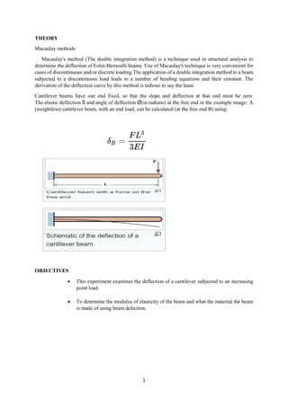
THEORY
Macaulay methods
Macaulay's method (The double integration method) is a technique used in structural analysis to
determine the deflection of Euler-Bernoulli beams. Use of Macaulay's technique is very convenient for
cases of discontinuous and/or discrete loading.The application of a double integration method to a beam
subjected to a discontinuous load leads to a number of bending equations and their constant. The
derivation of the deflection curve by this method is tedious to say the least.
Cantilever beams have one end fixed, so that the slope and deflection at that end must be zero.
The elastic deflection δ and angle of deflection Ø(in radians) at the free end in the example image: A
(weightless) cantilever beam, with an end load, can be calculated (at the free end B) using:
OBJECTIVES
This experiment examines the deflection of a cantilever subjected to an increasing
point load.
To determine the modulus of elasticity of the beam and what the material the beam
is made of using beam delection.
3. 3
Converting the masses used in the experiments to loads
Mass (grams) Load (newtons)
100 0.98
200 1.96
300 2.94
400 3.92
500 4.90
PROCEDURES
1. The width and depth of the aluminium, brass and steel were measured by vernier gauge.
2. The values were recorded to the results tables for each material and used them to calculate the
second moment area.
3. Clamps and knife edges from the backboard were removed.
4. One of the cantilevers was set up.
5. The digital dial test indicator was slide to the position on the beam.
6. A knife-edge hanger was slide to the position shown.
7. The frame lightly was tapped and the digital dial test indicator was zero using the ‘origin’ button.
8. The knife-edge was applied masses in the increments.
9. The frame lightly was tapped each time.
10. The digital dial test indicator were recorded for each increment of mass.
11. The procedure were repeated for the other two materials and filled in a new tables.
4. 4
RESULTS
material Brass
E value :1.05 x 10⁻¹⁶
Width b : 19.02 mm
I : 48.14 Depth d : 3.12 mm
Mass (g) Actual deflection (mm) Theoretical deflection (mm)
0 0 0
100 -0.7 5.170 x 10²⁰
200 -1.27 1.034 x 10²¹
300 -1.93 1.551 x 10²¹
400 -2.55 2.068 x 10²¹
500 -3.09 2.585 x 10²¹
material aluminium
E value :6.9 x 10⁻¹⁹
Width b : 19.3 mm
I : 68.96 Depth d : 3.5 mm
Mass (g) Actual deflection (mm) Theoretical deflection (mm)
0 0 0
100 -0.93 5.492 x 10²²
200 -1.63 1.098 x 10²³
300 -2.46 1.684 x 10²³
400 -3.21 2.197 x 10²³
500 -4.15 2.746 x 10²³
material Steel
E value :2.07 x 10⁻¹⁶
Width b : 19.01 mm
I : 57.20 Depth d : 3.3 mm
Mass (g) Actual deflection (mm) Theoretical deflection (mm)
0 0 0
100 -0.34 2.207 x 10²⁰
200 -1.74 4.414 x 10²⁰
300 -1.05 6.621 x 10²⁰
400 -2.40 8.829 x 10²⁰
500 -3.70 1.104 x 10²¹
CALCULATIONS
Theoretical deflection
Formula =
𝑊𝐿3
3𝐸𝐼
Where:
W= load(N)
L = distance from support to position of loading (m)
E = young’s modulus for cantilever material (N/m2
)
I = second moment of area of the cantilevel (m4
5. 5
Calculation for Brass material
For mass 100g
=
(0.98)×(200)3
3(1.05 ×10⁻¹⁶)(38.14)
= 5.170 x 10²²
mm
For mass 200g
=
(1.96)×(200)3
3(1.05 ×10⁻¹⁶)(38.14)
=1.034 x 10²¹
mm
For mass 300g
=
(2.94)×(200)3
3(1.05 ×10⁻¹⁶)(38.14)
=1.551 x 10²¹
mm
For mass 400g
=
(3.92)×(200)3
3(1.05 ×10⁻¹⁶)(38.14)
=2.068 x 10²¹
mm
For mass 500g
=
(3.92)×(200)3
3(1.05 ×10⁻¹⁶)(38.14)
=2.585 x 10²¹
mm
Calculation for Aluminium material
For mass 100g
=
(0.98)×(200)3
3(6.9 ×10⁻¹⁷)(68.96)
=5.492 x 10²⁰
mm
For mass 200g
=
(1..96)×(200)3
3(6.9 ×10⁻¹⁷)(68.96)
6. 6
=1.098 x 10²¹
mm
For mass 300g
=
(2.94)×(200)3
3(6.9 ×10⁻¹⁷)(68.96)
=1.648 x 10²¹
mm
For mass 400g
=
(3.92)×(200)3
3(6.9 ×10⁻¹⁷)(68.96)
=2.197 x 10²¹
mm
For mass 500g
=
(4.90)×(200)3
3(6.9 ×10⁻¹⁷)(68.96)
=2.745 x 10²¹
mm
Calculation for Steel material
For mass 100g
=
(0.98)×(200)3
3(2.07 ×10⁻¹⁶)(57.20)
=2.207 x 10²⁰
mm
For mass 200g
=
(1.69)×(200)3
3(2.07 ×10⁻¹⁶)(57.20)
=4.414x 10²⁰
mm
For mass 300g
=
(2.94)×(200)3
3(2.07 ×10⁻¹⁶)(57.20)
=2.207 x 10²⁰
mm
8. 8
OBSERVATION
From the experiment:
a. Graph of deflection versus mass for all three beams.
0
1
2
3
4
5
6
7
0 gram 100 gram 200 gram 300 gram 400 gram 500 gram
Brass
Actual Deflection theoretical Deflection
0
1
2
3
4
5
6
7
8
0 gram 100 gram 200 gram 300 gram 400 gram 500 gram
Aluminium
Actual Deflection theoretical Deflection
9. 9
b. Comment on the relationship between the mass and the beam reflection.
The more load the higher the value of deflection. The result of the experiment is more accurate
than the result using the calculation based on theory .
c. Is there a relationship between the gradient of the line for each graph and the modulus of the
material?
For aluminium, the line for theoretical deflection is ascending and descending.
For brass, the line for actual deflection is just straight line.
For steel, the line for theoretical deflection is from bottom to ascending and descending.
d. Three practical application of a cantilever structure.
Steel.
Concrete.
Bridges.
0
2
4
6
8
10
12
0 gram 100 gram 200 gram 300 gram 400 gram 500 gram
Steel
Actual Deflection theoretical Deflection
10. 10
CONCLUSION
In deflection of a cantilever, aluminium beam has the largest deflection, followed by brass beam and
steel beam has smallest deflection. The beam deflection is directly proportional to mass applied to the
beam. The higher the modulus of material, the smaller the gradient of the line for each graph. The
equation predicted the behaviour of beam which is in linear relationship. The theoretical deflection is
always lower than the actual deflection. In deflection of a simply supported beam, aluminium beam has
significantly less deflection in simply supported beam than in cantilever. Deflection of beam is directly
proportional to mass applied to the beam. Deflection of beam increased exponentially with distance
form support to position of loading
REFERENCES
1. Donald P.Codute (2012). Structure Engineering (2nd
ed). Us
2. Braja M.Das (2011). Principles of structure engineering (9nd ed). British
3. Robert D.Holtz (2010). A Introduction to structure Engineering (2nd
ed). British.
4. Robert W.Day (2009). structure engineers handbook (2nd
ed). Us