Downloaded 1,562 times
![CHAPTER 1
INTRODUCTION
1.1 Project Background
The communication has become the very important and necessary component
in our daily life to accomplish our tasks. People have to work together cooperatively
so that they come out with the solutions for certain problems. To share the information
resource among the people who look for solutions must have to be connected to each
other to facilitate the communication process. Majority of business organizations
nowadays depends on their network communication to achieve their desired business
goal. The reliability of the network has become one of the key factors among other
success and failure factors of an organization. If the network communication is not
reliable, there will be a lot of loss of resources including time and money. UNITEN
(Universiti Tenaga Nasional) is one of the organizations among other organizations
who rely on the reliability of their network communication to achieve their desired
goal. UNITEN has two campuses namely Putrajaya Campus and Muadzam Shah
Campus. Those two campuses are located in two different geographic locations and
both campuses have their own Intranet [1] operating inside each campus. The two
campuses are internet connected via TNB (Tenaga Nasional Berhad) Network which
operates by using MPLS (Multi-Protocol Label Switching) Protocol [2]. In this paper,
we will discuss about the underlying networking technology, protocols, equipment
and performance analysis by simulating the data collected from both actual network
users and ITMS UNITEN (IT & Media Service).](https://image.slidesharecdn.com/thereport-examplefyp-170109123954/85/Final-Year-Project-Report-Example-1-320.jpg)
![CHAPTER 1
INTRODUCTION
1.1 Project Background
The communication has become the very important and necessary component
in our daily life to accomplish our tasks. People have to work together cooperatively
so that they come out with the solutions for certain problems. To share the information
resource among the people who look for solutions must have to be connected to each
other to facilitate the communication process. Majority of business organizations
nowadays depends on their network communication to achieve their desired business
goal. The reliability of the network has become one of the key factors among other
success and failure factors of an organization. If the network communication is not
reliable, there will be a lot of loss of resources including time and money. UNITEN
(Universiti Tenaga Nasional) is one of the organizations among other organizations
who rely on the reliability of their network communication to achieve their desired
goal. UNITEN has two campuses namely Putrajaya Campus and Muadzam Shah
Campus. Those two campuses are located in two different geographic locations and
both campuses have their own Intranet [1] operating inside each campus. The two
campuses are internet connected via TNB (Tenaga Nasional Berhad) Network which
operates by using MPLS (Multi-Protocol Label Switching) Protocol [2]. In this paper,
we will discuss about the underlying networking technology, protocols, equipment
and performance analysis by simulating the data collected from both actual network
users and ITMS UNITEN (IT & Media Service).](https://image.slidesharecdn.com/thereport-examplefyp-170109123954/75/Final-Year-Project-Report-Example-1-2048.jpg)
![Page 3 of 68
o To generate report which is composed of maximum capability of the
network and network behaviors and user experiences during the time of
congestion
o To generate suggestion for optimizing the network to avoid network
congestion
1.4 Scope
To collect the actual traffic pattern, the survey called “Universiti Tenaga
Nasional Campus Putrajaya Network Utility Analysis” will be conducted to both
students and staffs. The data collected from the survey would be the input data which
will be using for simulation later on. To get information on actual campus network
architecture, an interview will be conducted to ITMS Network Admin. By using the
data from ITMS Network Admin, the campus network will be modeled in the
simulation project editor interface which includes the device vendor, link capacity,
routing protocols and packet propagation across the network. In this simulation
project, we will approach the simulation process by using OSI Model [3] (Open
System Interconnection Model) approach. We will be discussing and simulating on
OSL Layer 1, Layer 3, and Layer 7. The network administrators of UNITEN will
benefit from this simulation process since the simulation can realize what is happening
in the network and how much traffic and traffic types the network can support for
maximum extent. To simulate the campus network effectively, the simulation software
called simulator is needed. There are a number of simulators existing in the market
which include academic editions, commercial edition and open source. The study and
comparison of available network simulators will be done and the simulation process](https://image.slidesharecdn.com/thereport-examplefyp-170109123954/85/Final-Year-Project-Report-Example-3-320.jpg)
![CHAPTER 2
LITERATURE REVIEW
2.1 Introduction to Network Simulation
In this chapter, network design, network models, network simulators, network
simulation techniques, the network layer protocols which involve in network
simulation process, network topologies which involve in network simulation process,
the application layer protocols which involve in network simulation process and the
physical link models will be discussed.
2.1.1 Network Simulation
To implement an experimental network in a real time scenario is very difficult
because it can consume a lot of resource which include time and money. The network
simulators help the network designers and administrators to check whether the
network can perform as it is expected to do so in real time or not. To conduct network
functionality test by using network simulators can reduce a lot of time and money, and
also providing facilities to deploy the networks which are equal or similar to real time
scenario [4].](https://image.slidesharecdn.com/thereport-examplefyp-170109123954/85/Final-Year-Project-Report-Example-5-320.jpg)
![Page 6 of 68
2.1.2 Network Emulation
The author [5] said, the early work of network emulation involved “flake-
ways” which are the “gateways” that alter or drop the packets during TCP/IP tests.
The recent emulation involves the special purpose and stand-alone network emulators
which support packet delays and drops. The recent emulators looks likes the routers to
the end station which include PCs, Laptops and mobile phones. Those emulators were
developed by developers where they implement the systems as kernel drop-in modules
which intercept Network Layer packet forwarding path. Network emulators are
limited in capability and the maximum capability of emulator is simple packet
manipulation. The simple packet manipulation does not provide interference from
simulated cross traffic. The emulators do not support general simulation capabilities
which the network simulators do provide.
2.1.3 Network Modeling
According to the author [6], modeling is the process to produce model which is
the representation of real system of interest. The model has the similarity to the
system which the model represents but the model has higher simplicity than the
system. The purpose of modeling is to predict the effect of the changes made to the
system. A model should have the similarity with the real system as much as possible
and even should inherit the salient features of the system. On top of that, the model
should not be very complex so that it is easy to study and conduct experiment with it.
A good model has reality and simplicity. The complexity of the model will have to
increase iteratively during the experiment performing with the model. One of the
important issues in modeling is the model validity. To validate the model, the
experiment with the same input must be conducted on both model and the real system](https://image.slidesharecdn.com/thereport-examplefyp-170109123954/85/Final-Year-Project-Report-Example-6-320.jpg)
![Page 7 of 68
which the model represents. If the output from the model and the real system are the
same, the model is valid.
2.1.4 Network Planning and Designing
The author here said network planning and design is the process which executes
iteratively and covering topological design, network synthesis and network
realization. The aim of network planning and design is to ensure that new architecture
or design meet the requirement of the customers. The traditional network planning
methodology includes five layers of planning namely:
Business planning
Long-term and medium-term planning
Short-term planning
IT asset sourcing
Operation and maintenances
2.2 Types of Network Simulators
There are different types of network simulators that can be categorized based
on their availability, commercial or free, simple or complex.
2.2.1 Commercial and Open Source Simulators
Author [6] discussed that some of the network simulators are commercial and
it means that they will not provide source code of their software or the affiliated
packages to the general users for free of charge. All users have to pay for the license
or the specific module package which they want to use for their specific project
requirements. One of the typical example is OPNET which has two different license
type namely; commercial and academic license. For the users who want to use](https://image.slidesharecdn.com/thereport-examplefyp-170109123954/85/Final-Year-Project-Report-Example-7-320.jpg)
![Page 9 of 68
2.2.2 Simplicity and Complexity of Network Simulators
The author [6] said that currently, the great variety of network simulators are
available ranging from simple network simulators to very complex network
simulators. In general, a minimum function of network simulator include the network
simulator should enable users to represent a network topology, defining scenarios,
specifying the nodes (including node type and function) on the network, the links
between those nodes and the traffic generation capability among those nodes. The
more complicated network simulator allows users to specify everything about the
protocols used to process network traffic (i.e. Network Layer Protocols). Another
aspect of simplicity and complexity of network simulator is graphical user interface
(GUI). Network simulators which have GUI enabled, allow users to easily visualize
their works in the simulated environment. Some of the simulators may base on text-
based user interface which provide lesser visual or intuitive interface. Some of them
may be programming- oriented and can provide programming framework that allows
users to create an application which generate network traffic in network testing
environment.
2.3 Detail Discussion on Commonly Used Network Simulators
In this section, the discussion of OPNET, NS2, NS3 and OMNET++ will be
conducted in details since all of them are commonly used for network research and
development tasks.](https://image.slidesharecdn.com/thereport-examplefyp-170109123954/85/Final-Year-Project-Report-Example-9-320.jpg)
![Page 10 of 68
2.3.1 OPNET (Optimized Network Engineering Tool)
2.3.1.1 Overview
The development environment of OPNET simulator is called OPNET Modeler
[6]. OPNET Modeler is specialized for network research and development. OPNET
Modeler has flexibility that can be used to study communication networks, devices,
protocols, and applications. OPNET is the commercial software provider, then
OPNET offer relatively more powerful visual or graphical user interface for users.
The graphical interface can be used to create network topologies and entities from
Application Layer to Physical Layer. Object Oriented Programming technique is used
to create the mapping from the graphical design to the implementation of real systems.
The Figure 2.1 shows that GUI of OPNET. The users can see all the topology
configurations and simulation results which can be presented very intuitively and
visually. The simulation parameter such as amount of traffic generated, amount of
time for traffic generation or simulation can be adjusted to repeat the simulation for
different scenarios by using GUI. OPNET can run on both UNIX and Windows
platform.](https://image.slidesharecdn.com/thereport-examplefyp-170109123954/85/Final-Year-Project-Report-Example-10-320.jpg)
![Page 11 of 68
Figure 2.1 OPNET GUI [6]
OPNET system is based on discrete event simulation methodology which
means that the behavior of system can be simulated by modeling the events in the
system where user has to set the scenarios. Hierarchical structure is used to organize
the network which is unique to simulate hierarchical network architectures. The other
feature of OPNET is OPNET provide programming tools and interface for users
where users can define the packet format and protocols. The programming tools are
also required to simulate the networks since the tools provide techniques to define the
state of transition machine, network model, and process modules. Figure 2.2 shows
the OPNET Process editor Interface and Figure 2.3 shows the OPNET Node Editor
Interface.](https://image.slidesharecdn.com/thereport-examplefyp-170109123954/85/Final-Year-Project-Report-Example-11-320.jpg)
![Page 12 of 68
Figure 2.2 OPNET Process Editor Interface [7]
Figure 2.3 OPNET Node Editor Interface [7]
The OPNET is popular simulator used in both industry and academic for
network research and development. The GUI interface and Programing tools are very
useful to help users to build systems as complex as they want.](https://image.slidesharecdn.com/thereport-examplefyp-170109123954/85/Final-Year-Project-Report-Example-12-320.jpg)
![Page 13 of 68
2.3.1.2 Main Features
The author [6] said OPNET has three function inherently which are modeling,
simulating and analysis. For modeling, it provide graphical user interface which is
very intuitive. Users can create all kinds of models of protocols. For simulating,
OPNET uses 3 different advanced simulation technologies as said by the author [8].
For analysis, the simulation results and data can be analyzed and displayed using the
graphs and also generated web report. User friendly graphs, charts, statistics, and even
animations can be generated by OPNET analysis module for convenience of users.
According to OPNET whitepaper, OPNET’s detailed features include [6];
o Fast discrete even simulation engine
o Lot of component library with source code
o Object oriented modeling
o Hierarchical modeling environment
o Scalable wireless simulation support
o 32bit and 64bit software architecture of graphical user interface
o Customizable wireless modeling
o Discrete event, Hybrid, and analytical simulation
o Grid computing support
o Integrated GUI based debugging and analysis
o Open interface for integrating external component libraries](https://image.slidesharecdn.com/thereport-examplefyp-170109123954/85/Final-Year-Project-Report-Example-13-320.jpg)
![Page 14 of 68
2.3.2 Network Simulator 2 (NS2)
2.3.2.1 Overview
The author [6] discussed that NS2 is one of the most popular open source
network simulators. The original NS was discrete event network simulator targeted for
network research and development. NS2 is second version of NS (Network
Simulator). NS was based on REAL network simulator [9]. The first version was
developed in 1989. The current NS project is supported DARPA [9]. The current
second version (NS2) is widely used in academic research and has a lot of packages
contributed by non-profit organizations and groups. NS2 can run on UNIX platform.
2.3.2.2 Main Features
Author [9] discussed that NS2 is an objected oriented, discrete event driven
network simulator and was originally developed by University of California-Berkeley.
The programming used by NS2 is C++ and OTcl (Tcl scripting language with object-
oriented extensions developed at MIT). The biggest reason to use these two
programming languages is due to the internal characteristics and features of these two
programming languages. C++ is efficient to implement a design but it is not very easy
to be visualized and represented graphically. It is not easy to modify and assemble
different components and to change different parameters without very visual and easy
to use descriptive languages. On top of that, for efficiency reason, NS2 implemented
control path and data path separately. The event scheduler and basic network
component objects which has been written and compiled using C++ to reduce packet
and event processing time. The event scheduler and basic network components object
reside in data path. OTcl has the feature that C++ lack to have. Therefore, the](https://image.slidesharecdn.com/thereport-examplefyp-170109123954/85/Final-Year-Project-Report-Example-14-320.jpg)
![Page 15 of 68
combinations of these two programming languages prove to be very effective and
efficient. C++ is used to implement detailed protocols and OTcl used to implement for
users to control simulation scenario and schedule the events. Figure 2.4 shows the
simplified user view of NS2. To initiate the event scheduler, set up topology, and tell
packet traffic source when to start and stop sending packet according to event
scheduler, OTcl script is used. The scenario can be changed easily by programming
the OTcl script. If the user wants to create the new network object, the user can either
write the new object or assemble a compound object from the existing object library,
and plug the data path through the object. The plugging makes NS2 very powerful. NS
is developed in collaboration between DARPA [10], CONSER , ICIR, Sun
Microsystems, UCB and Carnegie Mellon Monarch Projects.
Figure 2.4 Simplified User View of NS2 [11]](https://image.slidesharecdn.com/thereport-examplefyp-170109123954/85/Final-Year-Project-Report-Example-15-320.jpg)
![Page 16 of 68
2.3.3 Network Simulator 3 (NS3)
2.3.3.1 Overview
Author here [6] discussed that NS3 is also open source discrete event network
simulator targeting primarily for research and educational use. NS3 is licensed under
GNU GPLv2 license and is available for research and development. NS3 is designed
to replace the current NS2. NS3 is not an updated version of NS2, which means that
NS3 is a new network simulator and not backward-compatible with NS2. NS3 can run
on UNIX platform.
2.3.3.2 Main Features
Author [6] informed that the basic idea of NS3 comes from several different
network simulators such as NS2, YANS [12], GTNetS [13]. The major differences
underlying between NS2 and NS3 are;
o Different software core: The core of NS3 is written in C++ and with Python
Scripting interface while NS2 was written in OTcl. Several advanced C++
design patterns are also used in NS3
o Attention to realism: protocol entities are designed to be closer to real
computers
o Software Integration: NS3 support integration of more open-source software
and reduce the needs to rewrite models for simulation
o Support for virtualization: lightweight virtual machines are used for
virtualization. Figure 2.5 shows the virtualization testbed of NS3.](https://image.slidesharecdn.com/thereport-examplefyp-170109123954/85/Final-Year-Project-Report-Example-16-320.jpg)
![Page 17 of 68
o Tracing architecture: NS3 is developing a tracing and statistics gathering
framework trying to enable customization of the output without rewriting or
rebuilding the simulation core.
Figure 2.5 Testbeds interconnect NS3 Stacks [11]](https://image.slidesharecdn.com/thereport-examplefyp-170109123954/85/Final-Year-Project-Report-Example-17-320.jpg)
![Page 18 of 68
2.3.4 OMNeT++
2.3.4.1 Overview
OMNeT++ has similarity with NS2 and NS3 such as public-source,
component-based network simulator with GUI support. The primary application area
of OMNeT++ is communication networks. OMNeT++ has flexible and generic
architecture and it has been successful simulator in other area like IT Systems,
queuing networks, hardware architectures and even business processes as well.
OMNeT++ is also a discrete event simulator and it is component-based architecture.
The components are also called modules and are programmed in C++ [14]. The
modules are programmed by using C++ programming language. The modules are
assembled into larger models by using high level programming language. The higher
level programming language function is similar to the function of OTcl in NS2 and
Python in NS3 [14]. GUI is supported by OMNeT++ as well. The simulation kernel
can be embedded into all kinds of different user’s applications because of its modular
architecture. OMNET++ can run on both UNIX and Windows platform. Figure 2.6
shows OMNeT++ GUI.
Figure 2.6 OMNeT++ GUI [11]](https://image.slidesharecdn.com/thereport-examplefyp-170109123954/85/Final-Year-Project-Report-Example-18-320.jpg)
![Page 19 of 68
2.3.4.2 Main Features
Author [14] discussed that modules or models of OMNeT++ are assembled from
reusable components since the architecture of OMNeT++ is component-based
architecture. One of the main feature of OMNeT++ include that the modules are
reusable and can be combined in various ways. The component of OMNeT++ include:
o Simulation kernel library
o Compiler for NED topology description language (nedc)
o Graphical Network Editor for NED files (GNED)
o GUI for simulation execution, links to simulation executable (Tkenv)
o Command line user interface for simulation execution (Cmdenv)
o Graphical output vector plotting tool (Plove)
o Graphical output scalars visualization tool (Scalars)
o Model documentation tool (opp_neddoc)
o Utilities such as random number seed generation tool and make file creation
tool, etc.)
o Documentation, sample simulation, etc.](https://image.slidesharecdn.com/thereport-examplefyp-170109123954/85/Final-Year-Project-Report-Example-19-320.jpg)
![Page 20 of 68
2.4 Comparison among NS2, NS3, OPNET, OMNeT++
2.4.1 Comparison of Advantages and Limitations in NS2
The author of [15] has discussed the advantages and limitations of NS2 as Table 2.1
Table 2.1 Comparison of NS2 Advantages and Limitations [15]
Advantages of NS2 Limitations of NS2
1. NS2 has larger number of available
models, realistic mobility models,
powerful and flexible scripting and
simulation setup, large user community
and ongoing development.
1. NS2 needs to be recompilation every
time if there is a change in the user code.
2. NS2 provides an easy traffic and
movement pattern by including an
efficient energy model.
2. Real system is too complex and it is
complicated infrastructure to model.
3. NS2 provides a set of randomized
mobility model and there are several
projects to bring advanced mobility
models to simulators.
3. The mixture of compilation and
interpretation made it difficult to analyse
and to understand the code.
4. Complex scenarios can be easily tested
by using NS2.
4. Including a lot of nodes in NS2 may
slow down the simulation process.
5. NS2 is popular for its modularity.](https://image.slidesharecdn.com/thereport-examplefyp-170109123954/85/Final-Year-Project-Report-Example-20-320.jpg)
![Page 21 of 68
2.4.2 Comparison of Advantages and Limitations in NS3
The author of [15] has discussed about advantages and limitations of NS3 as Table 2.2
Table 2.2 Comparison of NS3 Advantages and Limitations [15]
Advantages of NS3 Limitations of NS3
1. NS3 has high modularity than its
ancestor NS2.
1. NS3 still suffers from lack of
credibility.
2. NS3 support simulation for TCP, UDP,
ICMP, IPv4, multicast routing, P2P and
CSMA protocols.
2. NS3 is intended to replicate the
successful mode of NS2 in which a lot of
different organizations contributed to the
models and components based on the
framework of NS2.
3. NS3 support for ported code which
should make model validation easier and
more credible.
3. NS3 needs a lot of specialized
maintainers in order to avail the merits of
NS3 as the commercial OPNET network
simulator.
4. NS3 is much more flexible than NS2. 4. NS3 requires active maintainers to
respond to the user questions and bug
reports, to help test and validate the
system
5. Wide range of use in both optimization
and expansion of the existing networks.](https://image.slidesharecdn.com/thereport-examplefyp-170109123954/85/Final-Year-Project-Report-Example-21-320.jpg)
![Page 22 of 68
2.4.3 Comparison of Advantages and Limitations in OPNET
The author of [15] has discussed the advantages and limitations of OPNET as Table
2.3
Table 2.3 Comparison of OPNET Advantages and Limitations [15]
Advantages of OPNET Limitations of OPNET
1. OPNET leverage three different
simulation technologies to efficiently
trade off simulations detail and speed
1. Complex GUI operation
2. OPNET has fast discrete event
simulation engine.
2. OPNET does not allow much number
of nodes within a single connected
device.
3. OPNET has customizable wireless
modelling.
3. OPET result accuracy is by the
sampling resolution.
4. OPNET has integrated GUI based
debugging and analysis
4. OPNET simulation is inefficient if
nothing happens for long periods.](https://image.slidesharecdn.com/thereport-examplefyp-170109123954/85/Final-Year-Project-Report-Example-22-320.jpg)
![Page 23 of 68
2.4.4 Comparison of Advantages and Limitations in OMNeT++
The author of [15] has discussed the advantages and limitations of OMNeT++ as
Table 2.4
Table 2.4 Comparison of OMNeT++ Advantages and Limitations [15]
Advantages of OMNeT++ Limitations of OMNeT++
1. OMNeT++ provide a powerful GUI
environment
1. OMNeT++ does not offer a great
variety of protocols and very few
protocols have been implemented, leaving
users with significant background work.
2. OMNeT++ has tracing and debugging
module which are much easier than other
simulators.
2. OMNeT++ has poor analysis and
management of typical performance.
3. OMNeT++ has the ability to model
most hardware accurately and include the
modelling of physical phenomena.
3. OMNeT++ mobility extension is
relatively incomplete.](https://image.slidesharecdn.com/thereport-examplefyp-170109123954/85/Final-Year-Project-Report-Example-23-320.jpg)
![Page 24 of 68
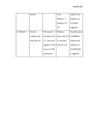
2.5 Minimum Hardware and Software Requirement for Network Simulators
The author of [15] suggested the minimum hardware and software requirement for
network simulators as Table 2.5
Table 2.5 Minimum hardware and software requirement for network simulators [15]
Network
Simulator
Type Programming
Languages
Supported
Operating
System
Hardware
Requirement
1.NS2 Open Source C++ and
Object-
Oriented Tool
Command
Language
(OTcL)
GNU/Linux,
FreeBSD, Mac
OS X,
Windows XP,
Windows
Vista,
Windows 7
Free disk space
of 5GB
required and
minimum of
256 MB of
RAM
suggested
2. NS3 Open Source C++ and
Optional
Python
Bindings
GNU/Linux,
FreeBSD, Mac
OS X,
Windows XP,
Windows
Vista,
Windows 7
Free disk space
of 5GB
required and
minimum of
256MB RAM
suggested
3. OPNET Commercial/
Free Academic
C and C++ Windows XP,
Windows
Free disk space
of 200MB](https://image.slidesharecdn.com/thereport-examplefyp-170109123954/85/Final-Year-Project-Report-Example-24-320.jpg)
![Page 26 of 68
2.6 Review of Network Simulation Methodologies
2.6.1 Discrete Event Simulation Method
Authors [16] discussed that discrete event simulation is the simulation method
which models the operation of real system as discrete sequence of events in time.
Each of the events occurs in particular time interval and this event marks a change of
system state. Between two consecutive events, there is no changes in the system is
assumed. Therefore, the simulation can directly jump from one event to another event.
The discrete event simulation is composed of:
State
A state of system is a variable set which captures the salient features and
properties of the real system of interest. The state trajectory overtime can be
represented mathematically by a step function [17]. The values of step function
change with respect to discrete events.
Clock
Current simulation time must be kept tracked by simulation in any
measurement units but they must be suitable for the system being modeled. In
discrete event simulation, the time ‘hop’ since the event is instantaneous. The
clock skips to next event start time as the simulation proceeds.
Event List
At least one list of simulation events are maintained by simulation process.
This is sometimes called pending event set since there are lists of events which
are pending to be simulated if the previous simulated event is not yet finished.
An event is denoted by the time at which it occurs and type. When the events
are instantaneous, the activities that extend over time are modeled as](https://image.slidesharecdn.com/thereport-examplefyp-170109123954/85/Final-Year-Project-Report-Example-26-320.jpg)
![Page 27 of 68
sequences of events. Single threaded simulation engines which are based on
instantaneous events have only one current event. Multi-threaded simulation
engine and simulation engines which support interval-based event modal may
have multiple current events.
Random number generators
The simulation process needs to generate various kinds of random variables
depending on the system model. To accomplish the random number generation
tasks, one or more Pseudorandom number generator [18]. The use of pseudo
random numbers are opposite from the use of true random numbers. The
benefit is if the simulation needs to re run again, the simulation will run again
with the exactly same behavior.
Statistics
The simulation keeps tracking of statistics of the system which quantify the
aspect of interest.
Ending Condition
Theoretically, the discrete event simulation could run forever since the events
are bootstrapped. Therefore, the simulation designer has to decide when the
simulation should end. The ending condition include “at certain time interval”,
after processing certain number of events” or generally “at the time if
statistical measurement of x reach the value of x”.](https://image.slidesharecdn.com/thereport-examplefyp-170109123954/85/Final-Year-Project-Report-Example-27-320.jpg)
![Page 28 of 68
2.6.2 Real time Simulation Method
The author [19] discussed that real time simulation method is a computer
model of a physical system which can execute as the same rate as the real clock time,
which means that the computer model runs at the same rate of the real physical
system. For example if a person will take to finish certain task with 10 minutes, the
person object in the simulation process would take 10 minutes to finish the task as
well. Real time simulation is dedicated and commonly used for computer gaming.
Real time simulators are used extensively in many of the engineering fields of study
such as statistical power grid protection tests, aircraft design and simulation, motor
drive controller design methods and space robot integration.
2.6.3 Continuous Simulation Method
Authors [20,21,22,23] discussed that continuous simulation methods is a
methodology which refers to a computer model of a physical system which track
system response continuously according to set of equations. Continuous simulation
allows prediction of rocket trajectories, hydrogen bomb dynamics, electric circuit
simulation and robotics. Continuous simulations are based on sets of differential
equation which defines peculiarity of the state variables, the environment factors to
speak, of a system. In the continuous simulation method, the conceptual model must
be constructed by using set of differential equations. To develop a conceptual model,
there are two approaches namely deductive approach and inductive approach. The
deductive approach states that the behavior of system arises from physical laws that
can be applied while the inductive approach states that the behavior of the system
arises from observed behavior of an actual example.](https://image.slidesharecdn.com/thereport-examplefyp-170109123954/85/Final-Year-Project-Report-Example-28-320.jpg)
![Page 29 of 68
2.7 Review of UNITEN current Network Architecture
Interview with UNITEN ITMS system analyst yield the information of current
network topology, hierarchical network architecture, routing protocols and network
applications used by UNITEN [43].
2.7.1 Topology Review
Currently, UNITEN Campus Network Architecture is based on Mesh Network
Topology and Start Network Topology. Fully Mesh Network topology is underlying at
the core network layer and the Star Network Topology is being implemented in both
Distribution and Access Network Layers.
Network Topology can be subdivided into physical network topology and
logical network topology [24].
2.7.1.1 Physical Network Topology
The author of [24] states that physical network topology emphasizes the
hardware associated with the systems which include, workstations, remote terminals,
servers, and associated wiring between assets. Figure 2.7 shows the physical topology
of a computer network.
Figure 2.7 Physical Network Topology [24]](https://image.slidesharecdn.com/thereport-examplefyp-170109123954/85/Final-Year-Project-Report-Example-29-320.jpg)
![Page 30 of 68
2.7.1.2 Physical Star Shape Topology
Author [24] said that start network topology requires the use of central node
which is at the top level and to which all other nodes are connected. The top level
node may be a computer, a switch, or just a common connection point. Messages
received by the top level node (such as Hub) can further be broadcasted to all
subordinate nodes or if the top level node (such as switch) is smart enough to send
only to the desired subordinate node. Inter node messaging delays are reduced with
this configuration. Failure in the connection between top level node and subordinate
node or failure in the subordinate node will not disrupt the entire network. This is an
important advantage of Star Network Topology. Star Network topology is commonly
used in a LAN [25] which span in larger geometric area. One of the disadvantages of
Star Network Topology is that it needs more cabling than any other network
topologies. Figure 2.8 shows a typical Star Network Topology.
Figure 2.8 Typical Star Network Topology [24]](https://image.slidesharecdn.com/thereport-examplefyp-170109123954/85/Final-Year-Project-Report-Example-30-320.jpg)
![Page 31 of 68
2.7.1.3 Physical MeshNetwork Topology
Author of [24] states that Mesh Network Topologies capitalize on path
redundancy. This topology is preferred if the traffic between node is large. Every node
in this type of network have multiple to another destination node. The probability of
single point network failure is greatly minimized with the Mesh Network Topology.
The major advantages of Mesh Network Topology is that source node determine the
best route from sender to destination based on connectivity, speed, pending node
tasks. A disadvantage of Mesh Network Topology is that it incur large cost when
implementation. There are two types of Mesh Network Topology namely Full Mesh
and Partial Mesh. In Full Mesh, each node being directly connected to every other
node in the network while in Partial Mesh, having some nodes in the network being
connected indirectly to the others in the network. Figure 2.9 shows the Full Mesh
Network Topology and Figure 2.10 shows the Partial Mesh Network Topology.
Figure 2.9 Typical Full Mesh Network Topology [24]](https://image.slidesharecdn.com/thereport-examplefyp-170109123954/85/Final-Year-Project-Report-Example-31-320.jpg)
![Page 32 of 68
Figure 2.10 Typical Partial Mesh Network Topology [24]
2.7.1.4 Logical Network Topology
The author of [24] states that the logical network topology which is also
known as signal topology emphasizes the representation of data flow between nodes.
Logical topology of the network can be dynamically reconfigured when selecting
network equipment such as router. Figure 2.11 showing logical topology of a
computer network.
Figure 2.11 Logical Network Topology [24]](https://image.slidesharecdn.com/thereport-examplefyp-170109123954/85/Final-Year-Project-Report-Example-32-320.jpg)
![Page 33 of 68
2.7.2 Routing Protocol Review
Currently, UNITEN Campus network routing process is based on two routing
protocols namely RIP and BGP [43].
2.7.2.1 Routing Information Protocol (RIP)
RIP is also known as Routing Information Protocol. RIP is Network Layer
protocol and true discrete vector Protocol. RIP sends out the complete routing table to
all active interfaces in every 30 seconds. RIP use hop count as the cost to determine
the best route to remote network. This hop count is limited to 15 by default and
meaning that the remote located at 16th hop count is not reachable. RIP is only
suitable for small networks and if the network is too large, RIP becoming inefficient
due to large numbers of router installed in the network. RIP version support only
class-full routing, this means that all devices in the network must use same subnet
mask. RIP version 1 does not send subnet mask information when it sends the routing
table update. In RIP version 2, there is something called prefix routing and hence
support classless routing by sending subnet mask information in route updates [26].
2.7.2.2 Border Gateway Protocol (BGP)
BGP is also known as Border Gateway Protocol. BGP is routing protocol
which operates at the network layer. BGP is used to exchange network layer
reachability information (NLRI) between routing domains. Routing domain is also
known as Autonomous System (AS) because different administrative authorities
control their own respective domains. The current internet is the network of
interconnected routing domains where BGP version 4 is the de facto routing protocol
[26].](https://image.slidesharecdn.com/thereport-examplefyp-170109123954/85/Final-Year-Project-Report-Example-33-320.jpg)
![Page 34 of 68
2.7.3 Underlying Networking Technology Review
Currently, UNITEN Campus networking technology is based on Ethernet
Technology [43]. Author of [27] states that Ethernet is the most widely used LAN
technology whose specific standard is IEEE 802.3. It was developed by organization
called Xerox and the specification was called Aloha net. Ethernet was for Palo Alto
Research Centre Aloha Network. It was further developed by Xerox, DEC and Intel.
Ethernet LAN typically used coaxial cable or special grades of twisted pair wires.
Wireless LAN also uses Ethernet. The most typically installed in Ethernet is 10BASE-
T which has the maximum transmission speed up to 10Mbps. The devices which are
connected to cable are in shared media. Those devices use Carrier Sense Multiple
Access with Collision Detection (CSMA/CD) protocol. 100BASE-T or also known as
Fast Ether is typically used for LAN backbone systems. This 100BASE-T provides
transmission speed up to 100Mbps. The workstations which has 10BASE-T card also
can use 100BASE-T fast Ethernet but the data transmission speed will be maximum of
10Mbps. Ethernet even provide even higher level backbone support at 1000 Mbps.
2.7.4 Network Architecture Review
Currently, the campus network of UNITEN is based on hierarchical network
design which consists of Core Layer, Distribution Layer and Access Layer [43].
2.7.4.1 Core Layer
According the author [28], he states that core layer of a network model is
crucial for interconnecting between distribution layer devices and outside internet.
The redundancy and availability is critical in the core layer. Normally, high](https://image.slidesharecdn.com/thereport-examplefyp-170109123954/85/Final-Year-Project-Report-Example-34-320.jpg)
![Page 35 of 68
performance routers are used as core layer devices since there is network address
translation between intranet and outside internet.
2.7.4.2 Distribution Layer
The author of [28] states that Distribution layer aggregate the data received
from all devices connected to access layer. After receiving the data from access layer
devices, distribution layer switches transmit the data to core network layer. High
performance switches are used in distribution since the load of data is relatively bigger
than access layer and to make sure the network has redundancy and high availability.
2.7.4.3 Access Layer
The author [28] discussed that Access layer allows end devices to be
connected to network via access switch or wireless access point. End user devices
include PCs, Laptops. Printers, Mobile phones and Tablets.
2.7.5 Review of Application Layer protocols used in UNITEN
2.7.5.1 File Transfer Protocol (FTP)
FTP is to promote sharing of files, to encourage indirect or implicit use of
remote computer programs, to shield user from variations in file storage systems
among hosts, and to transfer data reliably and efficiently. FTP is usable via a terminal
by the user but is designed mainly for use by programs. One of the FTP applications is
FileZilla [29].](https://image.slidesharecdn.com/thereport-examplefyp-170109123954/85/Final-Year-Project-Report-Example-35-320.jpg)
![Page 36 of 68
2.7.5.2 Hypertext Transfer Protocol (HTTP)
HTTP is known as Hypertext Transfer Protocol. HTTP has three versions
which are HTTP 1.0, HTTP 1.1 and HTTP 2.0. HTTP is stateless application layer
protocol for distributed, collaborative and hypertext information systems. HTTP is
popular in retrieving web related documents [30].
2.7.5.3 Voice over Internet Protocol (VoIP)
Voice over IP (VOIP) uses IP (Internet Protocol) to transmit voice as packet
over and IP Network. VOIP can be achieved on any data network which uses IP like,
Internet, Intranet, and Local Area Network (LAN). The motivations of internet
telephony are very low cost, demand for multimedia communication and demand for
integration of voice and data network. Some of the popular protocols in VOIP are
H.323, Session Initiation Protocol (SIP) [31].
2.7.5.4 Simple Mail Transfer Protocol (SMTP)
SMTP is also known as Simple Mail Transfer Protocol. SMTP is used for
transporting electronic mail among different hosts within department of Defense
Internet Protocol Suite. A user SMTP process opens a TCP connection to a server
SMTP process on a remote host to send mail via the connection. SMTP process from
server listen for TCP connection via well-known port 25 and user SMTP process
initiate a connection to that port. If the TCP connection is successfully established
between server SMTP process and user SMTP process, simple request and response
dialogue/message are executed defined by SMTP Protocol. The message must contain
a message header and message text formatted [32].](https://image.slidesharecdn.com/thereport-examplefyp-170109123954/85/Final-Year-Project-Report-Example-36-320.jpg)
![Page 37 of 68
2.7.5.5 Post Office Protocol version 3 (POP3)
POP3 is also known as Post Office Protocol version 3. POP is one of the
methods of accessing email. POP3 is older than IMAP. POP3 does not maintain folder
hierarchy in server side so that user may have difficulty to retrieve email if user has to
access from different computer rather than usual one [33].
2.7.5.6 Internet Message Access Protocol (IMAP)
IMAP is also known as Internet Message Access Protocol. IMAP is one of the
methods of accessing email as well. IMAP provides server-side storage and
manipulation of email. IMAP works better than POP3 if user has to access email via
multiple computer and also via web. IMAP maintain email folder hierarchy in server
side [33].
2.7.6 Review of Transport Layer Protocols used in UNITEN
2.7.6.1 Transmission Control Protocol (TCP)
TCP is Transport Layer Protocol. TCP is connection oriented since TCP
implement the mechanism to setup and tear down a full duplex connection between
end points. The data sent over network via TCP is guaranteed that the receiver will
receive correctly and completely since TCP has mechanism for error free and in order
delivery of data. TCP also has flow control and congestion control mechanism which
control traffic within transmission links [34].](https://image.slidesharecdn.com/thereport-examplefyp-170109123954/85/Final-Year-Project-Report-Example-37-320.jpg)
![Page 38 of 68
2.7.6.2 User Datagram Protocol (UDP)
UDP is also Transport Layer Protocol. UDP is connectionless protocol and
datagrams are delivered independently. UDP is not reliable in transmission of data
since UDP cannot guarantee for data loss, corruption, and duplication and in order
delivery [34]](https://image.slidesharecdn.com/thereport-examplefyp-170109123954/85/Final-Year-Project-Report-Example-38-320.jpg)

![Page 44 of 68
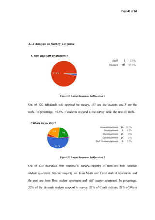
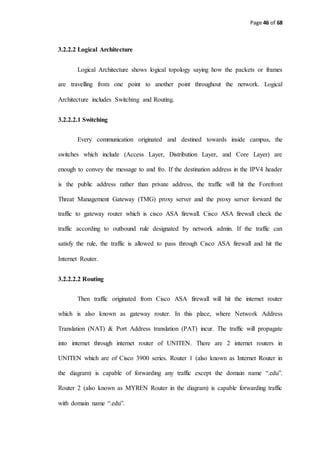
3.2.1 Analysis on UNITEN Network Architecture
KSHAS LAN
Internet Internet
Murni Core
BC Core
BC Core 1
Murni 3 Core
BC Lab
Murni 1
Core
Murni 2
Core
Masjid Uniten
Core
Ilmu
Distribution
Ilmu Core
DSS
C2 Core
C1 Core
C2 Core
A6
A5
A4
Amanah
Distribution
A3
A2
A1
BGP
LEGEND
Multi Mode Fiber Optic
1Gb/s
Single Mode Fiber Optic
1Gb/s
Uniten Putrajaya Kampus Network Architecture
A1 L4
Wireless
Bridge
Staff Quarters
Cat 5e 100Mb/s
Internet
Router MyRenRouter
Cisco ASA
Firewall
Library Core
Switch
Admin Core
Switch
Muadzamshah
Kampus Core
Switch
COE Core
Switch
COIT Core
Switch
Figure 3.7 UNITEN Putrajaya Campus Network Architecture [43]
3.2.2 Analysis and Discussion on UNITEN Network Architecture
3.2.2.1 Physical Architecture
UNITEN Network is a converged and hierarchical network model which
consists of Core Layer, Distribution Layer and Access Layer [43].
3.2.2.1.1 Core Layer
There are 4 core layer switches (Cisco C6509) which locates in Library Block,
Administrative Block, College of Computer Science and Information Technology
Block and College of Engineering Block. These 4 core switches are connected with
Single Mode Fiber Optic Cables since the distance between them is quite far and the
Multi-Mode Fiber Optic Cable cannot capable of conveying electrical signals. From](https://image.slidesharecdn.com/thereport-examplefyp-170109123954/85/Final-Year-Project-Report-Example-44-320.jpg)

![Page 47 of 68
3.3 Network Simulator Analysis
In this section, the analysis of network simulator software which will be
adopted for this project will be discussed.
3.3.1 OPNET for Campus Network Simulation
The OPNET was chosen as Network Simulator for this project since there are
a lot of several literature reviews on OPNET to simulate campus network. The
authors of [35] performance analysis by using OPNET is at SUNY College at
Fredonia, New York. The Project was to satisfy the increasing demands of network
resource; the college has to implement the Switch Ethernet Subnets and Gigabit
Ethernet Backbone. To implement the VoIP and video conferencing for future
development, the researchers from said university used OPNET to estimate and
visualize the ability of the network. Their works focused on performance
measurement and improvement in network capability by using innovative algorithms
and identification of potential bottlenecks in communications. They model the campus
network using OPNET. For them, the various features provided by OPNET were very
handy such as custom model creation for the elements which are not present in the
built in models.
There are many other campus network simulated and analyzed by using
OPNET Modeler such as the universities in China [36], the university of Sheffield
[37], IPv6 deployment of Zhaoqing university in China [38], the fault tolerant campus
area network of universities in Nigeria [39], the campus back bone of university in
Belgium [40] and so on.](https://image.slidesharecdn.com/thereport-examplefyp-170109123954/85/Final-Year-Project-Report-Example-47-320.jpg)
![Page 48 of 68
3.3.2 Protocols supported by OPNET
The OPNET Modeler comprises of protocols and technologies with
sophisticated development environment. By modeling all network types and
technologies in the modeler, riverbed Modeler analyze networks to compare the
impact of different technology design on end-to-end behavior. These technologies
include VoIP, TCP, OSPFV3, MPLS, IPV6 and many more. Riverbed Modeler let us
test and demonstrate technology designs before it is actually implemented hence
enhancing network research & development productivity and evaluate enhancement to
standard based protocols [41].
3.3.3 OPNET Features
The features of OPNET provide the ease of use which include [15];
o OPNET has three main functions; modeling, simulating and analysis
o OPNET provide intuitive graphical environment to create all kind of protocol
models.
o OPNET consists of high level user interface which is constructed from C and
C++ source code blocks with a library of OPNET Specific functions.
o OPNET arrange its hierarchical model into three specific domains: Network
domain, Node domain, and Process domain.
o OPNET model network protocols, resources, algorithms, applications and
queuing policies in detail using OPNET Modeler’s powerful object-oriented
modeling approach.
The hardware requirement and the platform support also one of the reasons to
choose OPNET as a modeler and simulator for this project. The programming in](https://image.slidesharecdn.com/thereport-examplefyp-170109123954/85/Final-Year-Project-Report-Example-48-320.jpg)
![Page 49 of 68
OPNET modeler can be done using flavor C and C++ language. The hardware
requirement is affordable requirement which is 200MB of disk space and 256MB of
RAM to run OPNET on Windows based platform.
3.3.4 OPNET for UNITEN Campus Network Simulation
Simulation processes which can be carried out with OPNET for this project
include, IPV4, traffic generation based on different types of application, routing
protocols, different network technologies including Ethernet, firewall.
3.4 Network Simulation Methodology Analysis
The discrete event simulation methodology will be adopted because discrete event
simulation provide the followings features and advantages [42],
o Discrete event simulation is used to enact the system that have a queue
network model (delay) as well as to compare and predict the outcome of a
particular scenario.
o Discrete event simulation focuses on the process that involves the use of
queue.
o Discrete event simulation is mostly used in decision and prediction making.
o Discrete event simulation is used at the operational level and it is top down
approach
o ‘Discrete event simulation is easy for user to understand with the help of
animations and graphics that build in the OPNET Modeler.
o Having unlimited flexibility to determine the behavior of entities.
o Straighter forward to be modeled once the problem has been clearly defined](https://image.slidesharecdn.com/thereport-examplefyp-170109123954/85/Final-Year-Project-Report-Example-49-320.jpg)
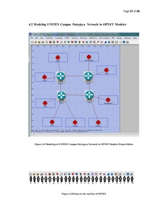
![Page 51 of 68
Figure 4.1 Network Level Main Window for Wide Area Network Simulation[15]
Figure 4.2 Subnet of network nodes [15]](https://image.slidesharecdn.com/thereport-examplefyp-170109123954/85/Final-Year-Project-Report-Example-51-320.jpg)
![Page 52 of 68
4.1.2 Node Domain Design
Figure 4.3 Individual Network Node Modeling[15]
The node model specifies the internal structure of a network node. Generally,
network nodes include workstations, packet switches, satellite terminals and remote
sensors. Node can be fixed, mobile or satellite type. The node can be modeled
according OSI model which include application layer, presentation and session layer
(application interface), transport layer (TCP & UDP), Network Layer (IP), Link Layer](https://image.slidesharecdn.com/thereport-examplefyp-170109123954/85/Final-Year-Project-Report-Example-52-320.jpg)
![Page 53 of 68
(ARP & MAC), Physical Layer (receiver & transmitter). Figure 4.4 shows that a node
has been modeled internally according to OSI reference model.
Figure 4.4 Node model with OSI[15]
4.1.3 Process Domain
Process models are used to specify the behavior of a processor and queue
modules which exists in the Node Domain. A module is modeled as finite state
machine (FSM) and consists of states with transition and condition between them.
Figure 4.5 shows the machine states and transition in the process domain editor.](https://image.slidesharecdn.com/thereport-examplefyp-170109123954/85/Final-Year-Project-Report-Example-53-320.jpg)
![Page 54 of 68
Figure 4.5 States and Transitions of a FSM in the Process domain editor [15]
The process can be edited by using the source code editor as shown in Figure 4.6 and
Figure 4.7 below.
Figure 4.6 Process Editor Interface [15]](https://image.slidesharecdn.com/thereport-examplefyp-170109123954/85/Final-Year-Project-Report-Example-54-320.jpg)
![Page 55 of 68
Figure 4.7 Process Source Code Editor [15]
4.1.4 Simulation Tool Design
The simulation tool of OPNET modeler can combine several low level
attributes (network domain, node domain, process domain) and make series of
simulation iteratively. The result will be generated by OPNET Simulator after the
simulation process. Figure 4.6 shows the simulation sample.](https://image.slidesharecdn.com/thereport-examplefyp-170109123954/85/Final-Year-Project-Report-Example-55-320.jpg)
![Page 56 of 68
Figure 4.8 Sample Simulation and generated report in graph format [15]](https://image.slidesharecdn.com/thereport-examplefyp-170109123954/85/Final-Year-Project-Report-Example-56-320.jpg)
![Page 63 of 68
REFERENCES
[1] M. Rajalampi, “The role of the intranet in enhancing communication and
knowledge sharing in a multinational company : Create , store , retrieve ,
transfer , use and share information !,” 2011.
[2] “Multiprotocol Label Switching (MPLS).” [Online]. Available:
http://www.cisco.com/c/en/us/products/ios-nx-os-software/multiprotocol-label-
switching-mpls/index.html. [Accessed: 10-Sep-2015].
[3] M. N. O. Sadiku and M. Ilyas, Simulation of Local Area Networks. CRC Press,
1994.
[4] L. D. A. Moltchanov, “Network simulation and simulators.”
[5] H. P. Pfeifer, “Network Emulation.”
[6] J. Pan, “A Survey of Network Simulation Tools: Current Status and Future
Developments,” pp. 1–13, 2008.
[7] “Introduction to Using OPNET Modeler.”
[8] J. Prokkola, “Opnet-network simulator,” … tietoliikennetekniikan simuloinnit ja
tyokalut/Opnet …, pp. 1–18, 2006.
[9] S. Keshav, “REAL: A network simulator.” 1988.
[10] T. Issariyakul and E. Hossain, Introduction to Network Simulator NS2. Springer
Science & Business Media, 2011.
[11] S. Siraj, A. K. Gupta, and Badgujar-Rinku, “Network Simulation Tools
Survey,” Int. J. Adv. Res. Comput. Commun. Eng. Vol. 1, Issue 4, June 2012,
vol. 1, no. 4, pp. 201–210, 2012.
[12] M. Lacage and T. R. Henderson, “Yet another network simulator,” Proceeding
from 2006 Work. ns-2 IP Netw. simulator - WNS2 ’06, p. 12, 2006.
[13] G. Riley, “The Georgia Tech network simulator,” Proc. ACM SIGCOMM
Work. Model. methods tools Reprod. Netw. Res. (MoMeTools ’03 ), no. August,
pp. 5–12, 2003.](https://image.slidesharecdn.com/thereport-examplefyp-170109123954/85/Final-Year-Project-Report-Example-63-320.jpg)
![Page 64 of 68
[14] “OMNeT++ Discrete Event Simulator - Documentation.” [Online]. Available:
https://omnetpp.org/documentation. [Accessed: 10-Sep-2015].
[15] M. H. Kabir, S. Islam, J. Hossain, and S. Hossain, “Detail Comparison of
Network Simulators,” vol. 5, no. 10, pp. 203–218, 2014.
[16] Stewart Robinson and S. Robinson, Simulation – The practice of model
development and use. Wiley, 2004.
[17] Bachman, Narici, Beckenstein and N. Bachman, Example 7.2.2. Springer, New
York, 2000.
[18] Niels Ferguson, Bruce Schneier, Tadayoshi Kohno and B. S. Niels Ferguson,
Cryptography Engineering: Design Principles and Practical Applications,
Chapter 9.4: The Generator. 2010.
[19] “Real-time simulation - Wikipedia, the free encyclopedia.” [Online]. Available:
https://en.wikipedia.org/wiki/Real-time_simulation. [Accessed: 10-Sep-2015].
[20] Louis G. Birta, Gilbert Arbez and G. A. Louis G. Birta, Modelling and
Simulation, p. 288. Springer, 2007.
[21] Louis G. Birta, Gilbert Arbez and G. A. Louis G. Birta, Modelling and
Simulation, p. 282. Springer, 2007.
[22] Louis G. Birta, Gilbert Arbez and G. A. Louis G. Birta, Modelling and
Simulation, p. 255. Springer, 2007.
[23] Louis G. Birta, Gilbert Arbez and G. A. Louis G. Birta, Modelling and
Simulation, p. 249. Springer, 2007.
[24] B. Meador, “A Survey of Computer Network Topology and Analysis Examples
Keywords :,” pp. 1–11, 2008.
[25] a a Atayero, a S. Alatishe, and J. O. Iruemi, “Modeling and Simulation of a
University LAN in OPNET Modeller Environment,” pp. 1–4.
[26] U. D. Black, IP Routing Protocols: RIP, OSPF, BGP, PNNI, and Cisco Routing
Protocols. Prentice Hall Professional, 2000.
[27] T. Lammle, CCNA: Cisco Certified Network Associate: Fast Pass. John Wiley
& Sons, 2008.
[28] J. Tiso and D. Teare, Designing Cisco Network Service Architectures (ARCH):
Foundation Learning Guide. Cisco Press, 2011.
[29] G. Meurant, Kermit: A File Transfer Protocol. Elsevier, 2013.
[30] C. Shiflett, HTTP Developer’s Handbook. Sams Publishing, 2003.](https://image.slidesharecdn.com/thereport-examplefyp-170109123954/85/Final-Year-Project-Report-Example-64-320.jpg)
![Page 65 of 68
[31] J. Davidson, Voice Over IP Fundamentals. Cisco Press, 2006.
[32] D. Hanes and G. Salgueiro, Fax, Modem, and Text for IP Telephony. Cisco
Press, 2008.
[33] T. Lammle, CCNA Cisco Certified Network Associate Deluxe Study Guide.
John Wiley & Sons, 2011.
[34] G. Held, TCP/IP Professional Reference Guide. CRC Press, 2000.
[35] J. A. Zubairi and M. Zuber, “Suny Fredonia Campus Network Simulation and
Performance Analysis Using Opnet,” New York, pp. 1–5.
[36] Z. Kaiyu, G. Xuefei, A. Yongli, and L. Jiayu, “Simulation for Upgrade Scheme
Optimization of Campus Network,” vol. 11, no. 8, pp. 4267–4272, 2013.
[37] U. H. Diala and C. I. Ndukwe, “Design , Simulation and Pilot Implementation
of a Campus Area Network That Supports Teleconferencing,” vol. 2, no. 4, pp.
550–556, 2015.
[38] L. Zhao, F. Yang, and Y. Zhao, “The Simulation Research of Campus Network
Technology Based on IPv6,” vol. 4, pp. 190–195, 2013.
[39] B. R. Olayeni, “Simulation of a Fault Tolerant University Campus Area
Network,” vol. 5, no. 5, 2015.
[40] J. Potemans, J. Theunis, B. Rodiers, P. Leys, and E. Van Lil, “Simulation of a
Campus Backbone Network, a case-study,” pp. 1–6.
[41] “SteelCentral Network Performance Management | Riverbed Modeler |
Riverbed.” [Online]. Available:
http://www.riverbed.com/products/performance-management-control/network-
performance-management/network-simulation.html. [Accessed: 10-Sep-2015].
[42] S. Sumari and R. Ibrahim, “Comparing Three Simulation Model Using
Taxonomy: System Dynamic Simulation, Discrete Event Simulation and Agent
Based Simulation,” Int. J. Manag. Excell., vol. 1, no. 3, pp. 4–9, 2013.
[43] E. Faizal, 'Uniten Network Architecture', Uniten Kampus Putrajaya, 2015.](https://image.slidesharecdn.com/thereport-examplefyp-170109123954/85/Final-Year-Project-Report-Example-65-320.jpg)


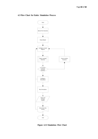
This document outlines a project focused on simulating and analyzing the network architecture of Universiti Tenaga Nasional (Uniten) Putrajaya to address issues of network congestion. The project aims to identify traffic patterns and optimize network performance by employing various simulation methodologies and tools. Key objectives include generating reports on network capacity and behavior during congested periods, which will aid in the decision-making process for network improvements.