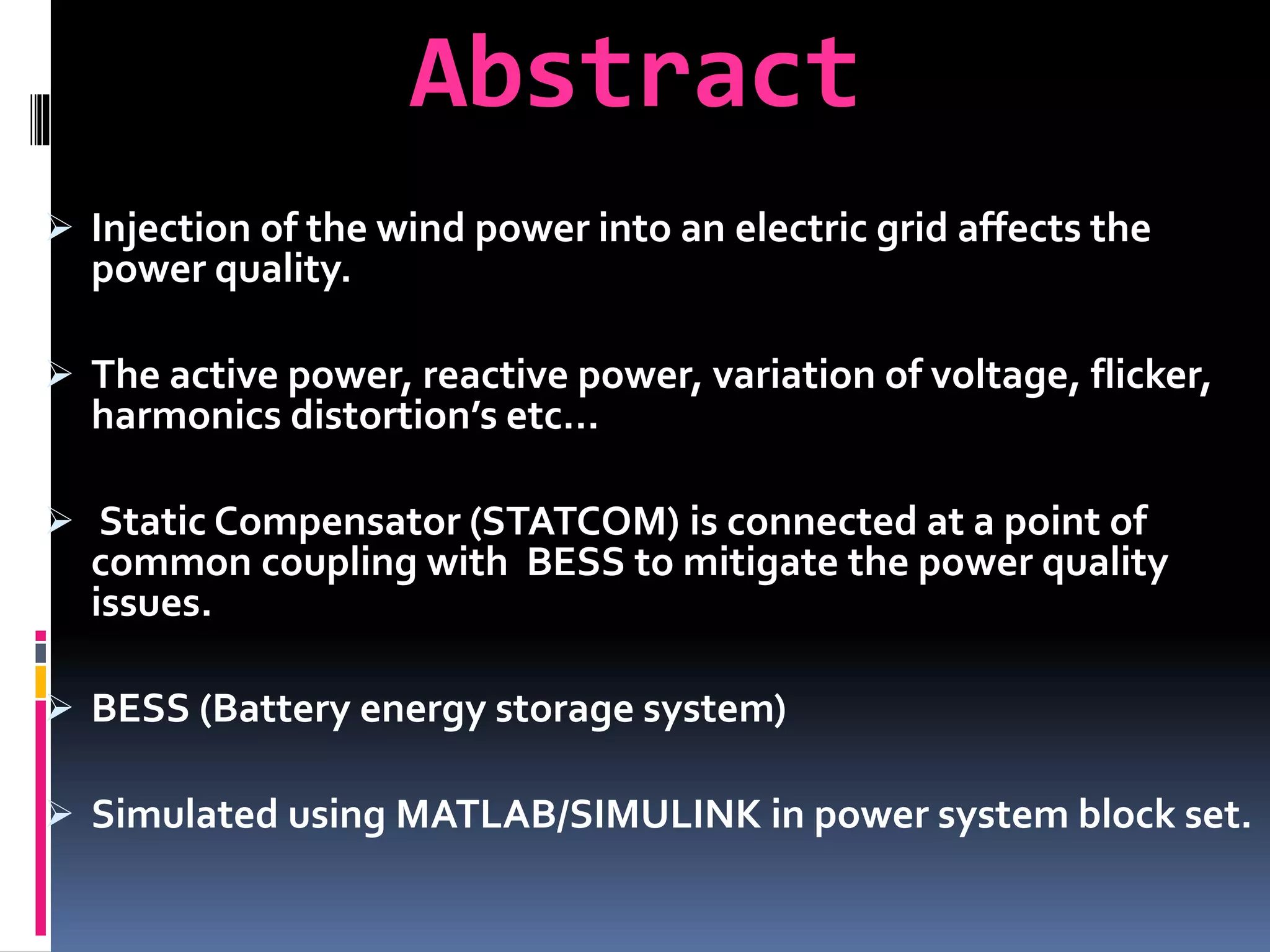
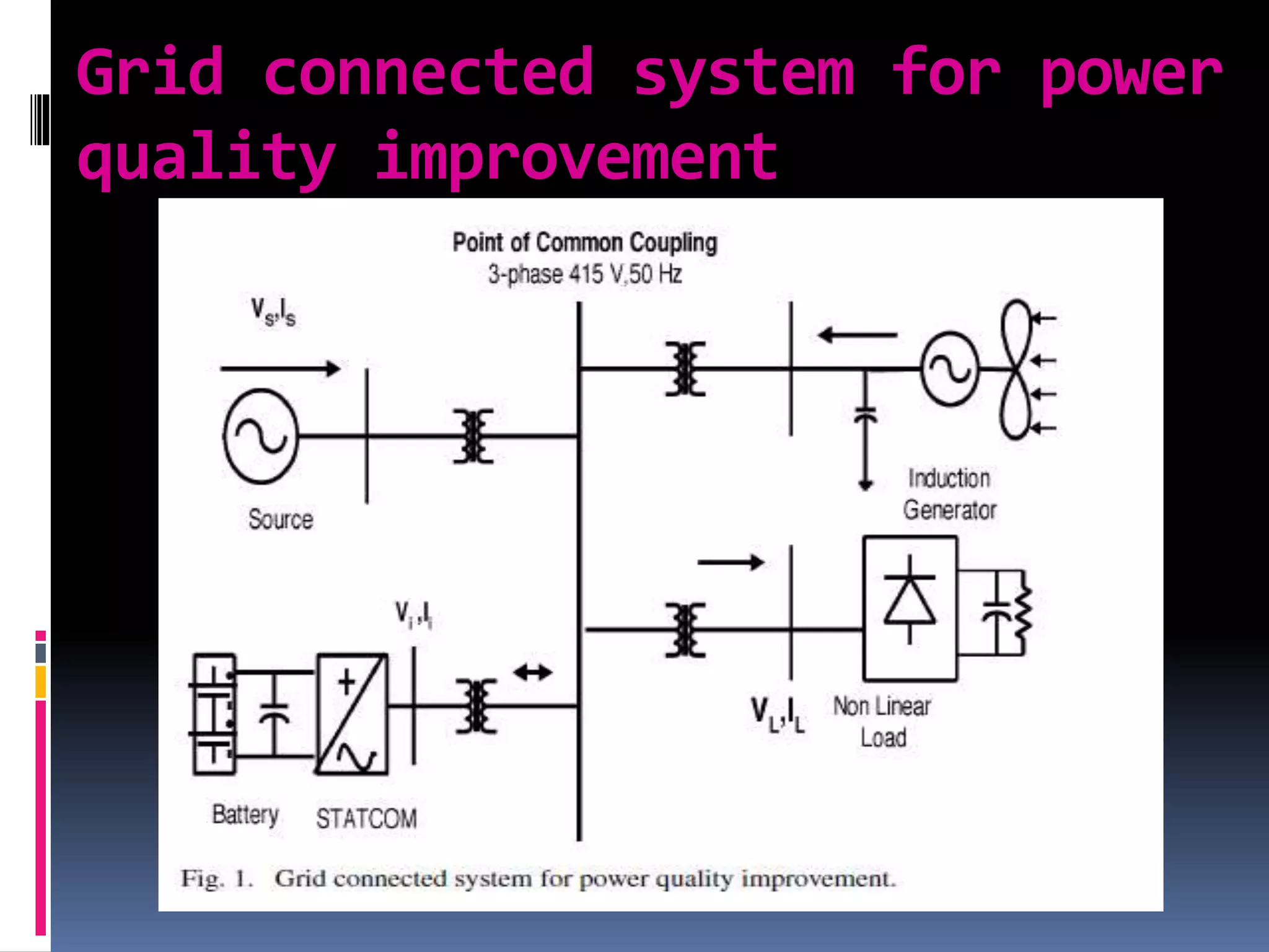
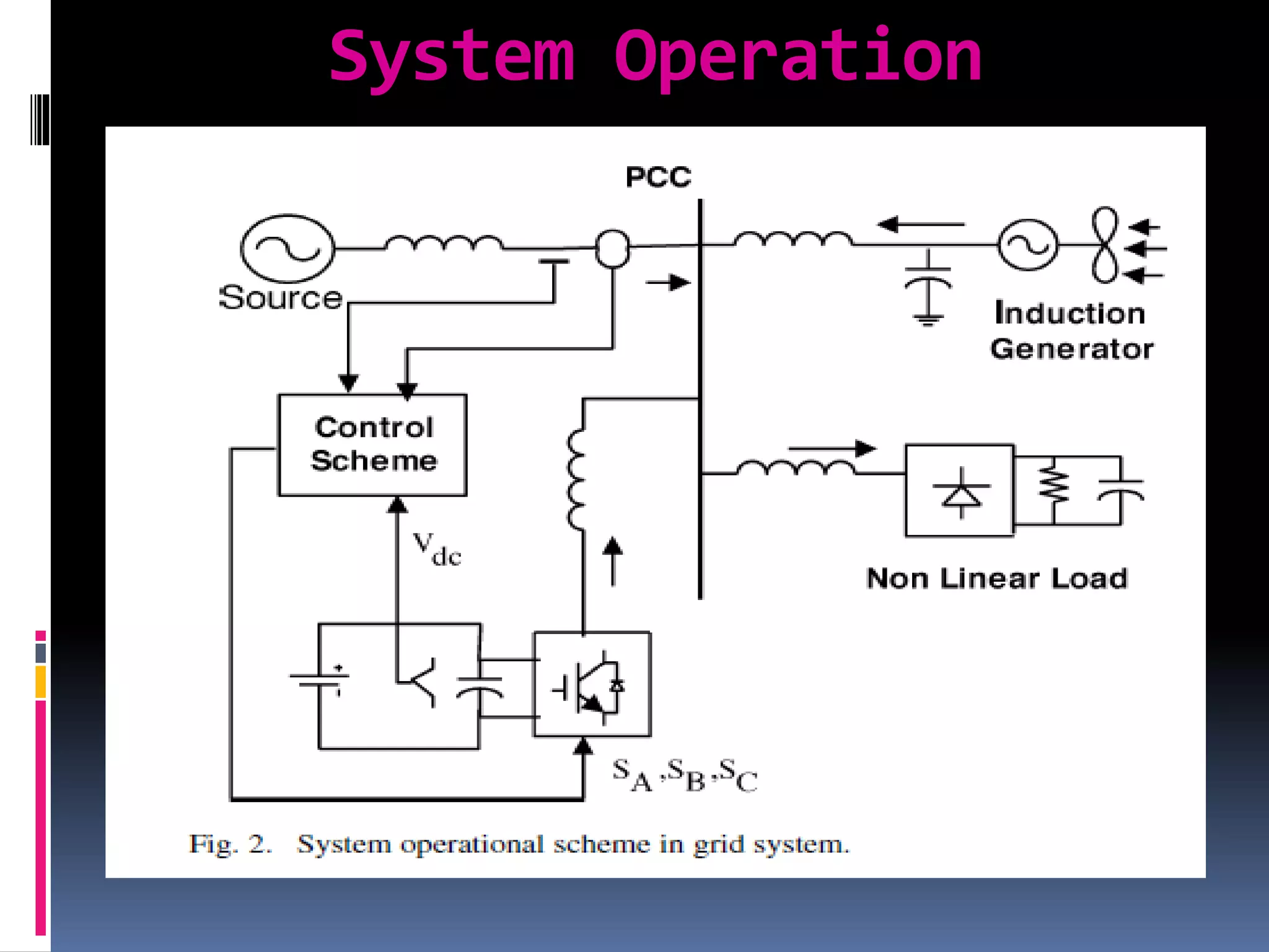
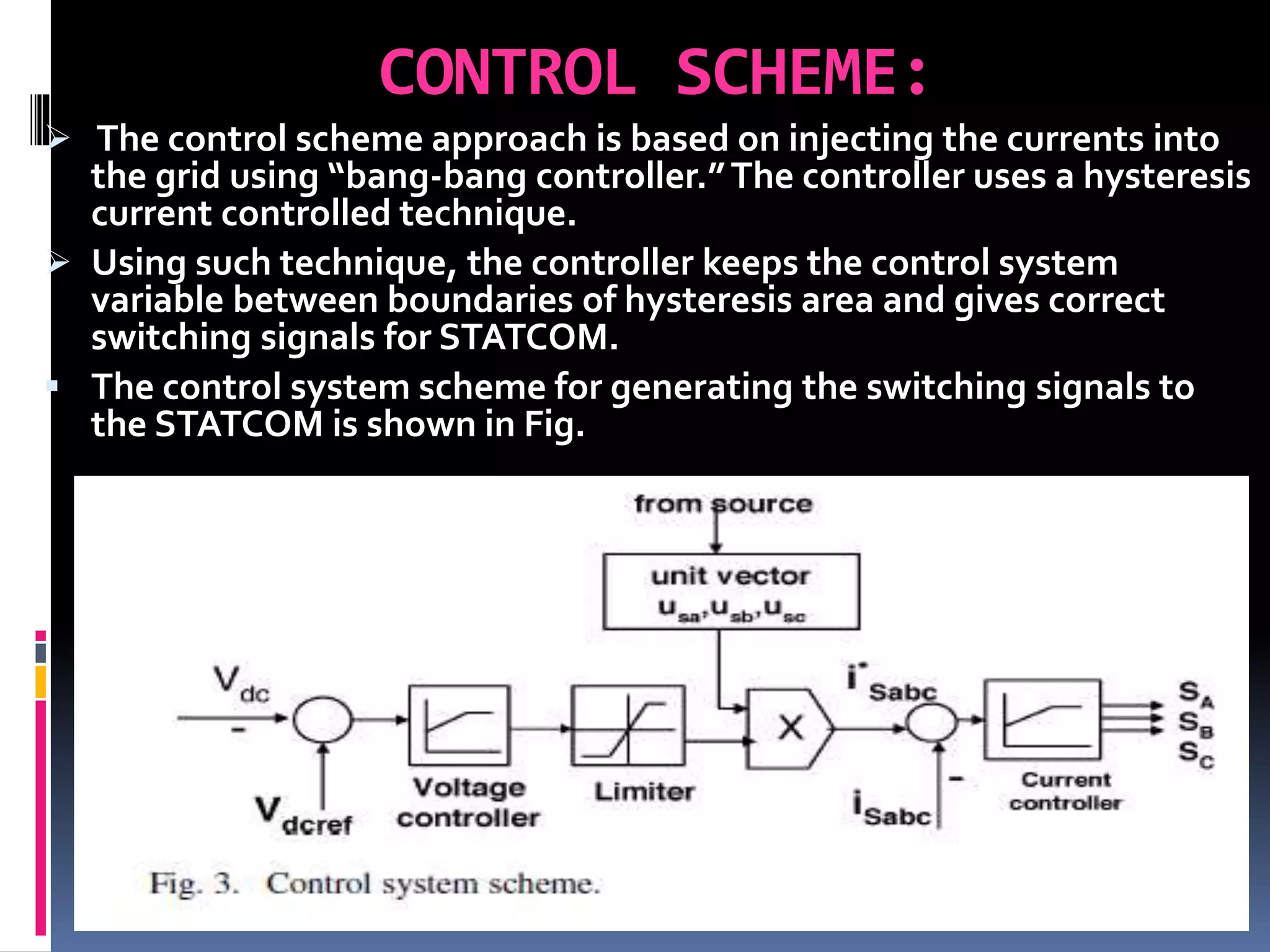
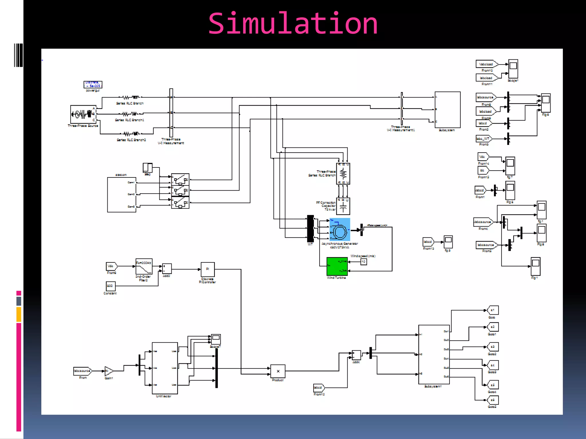
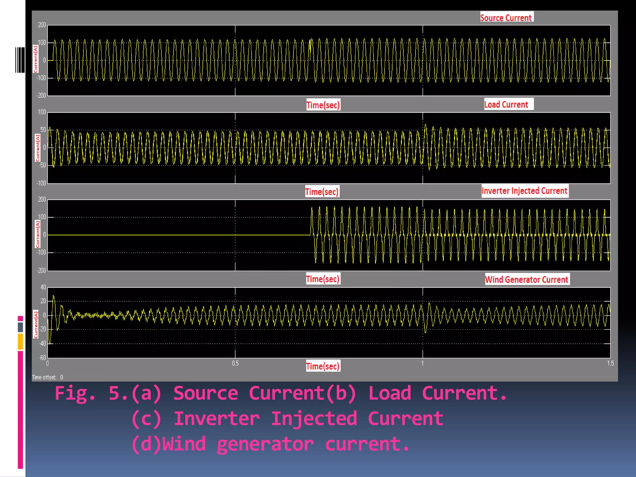
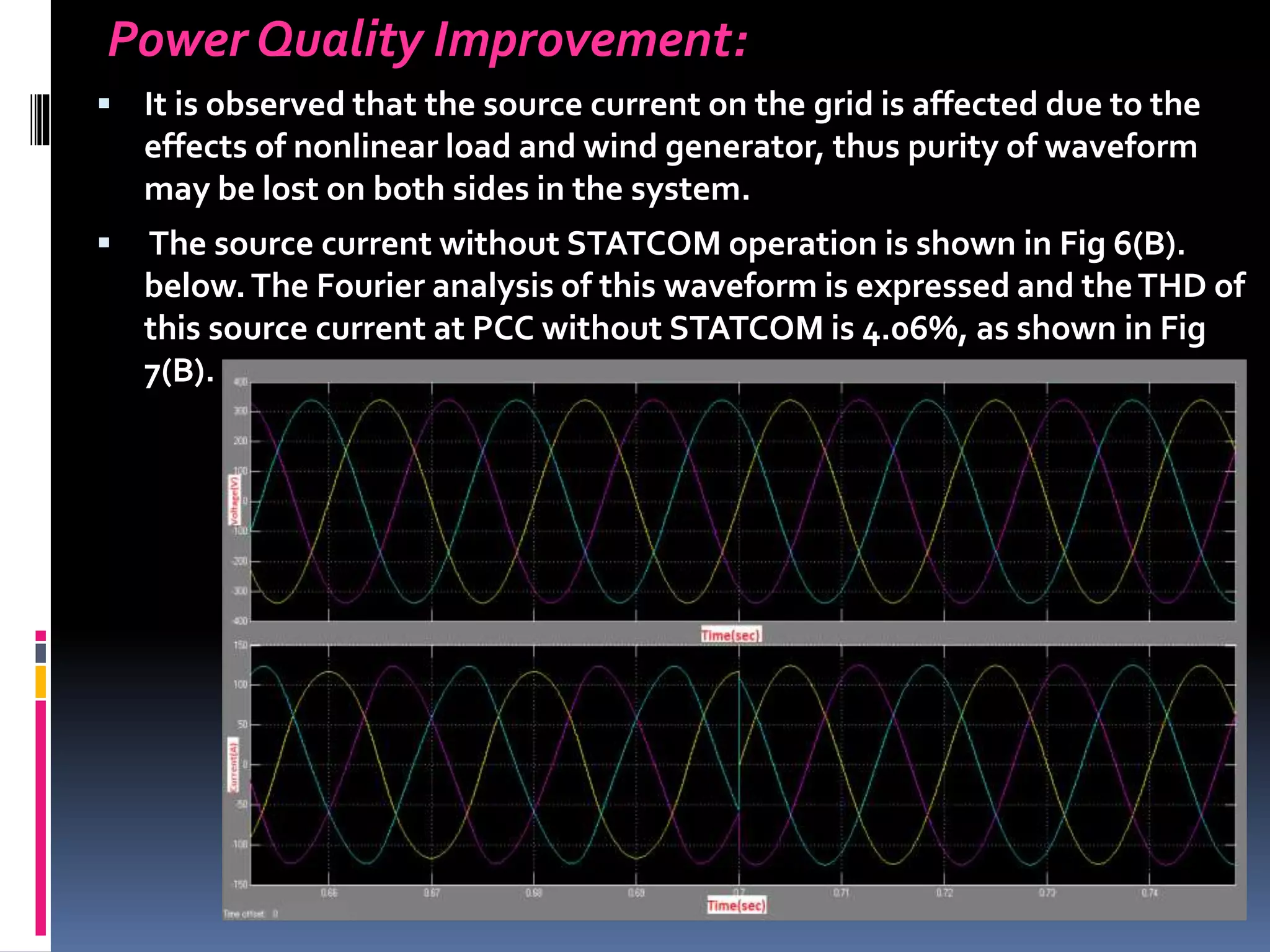
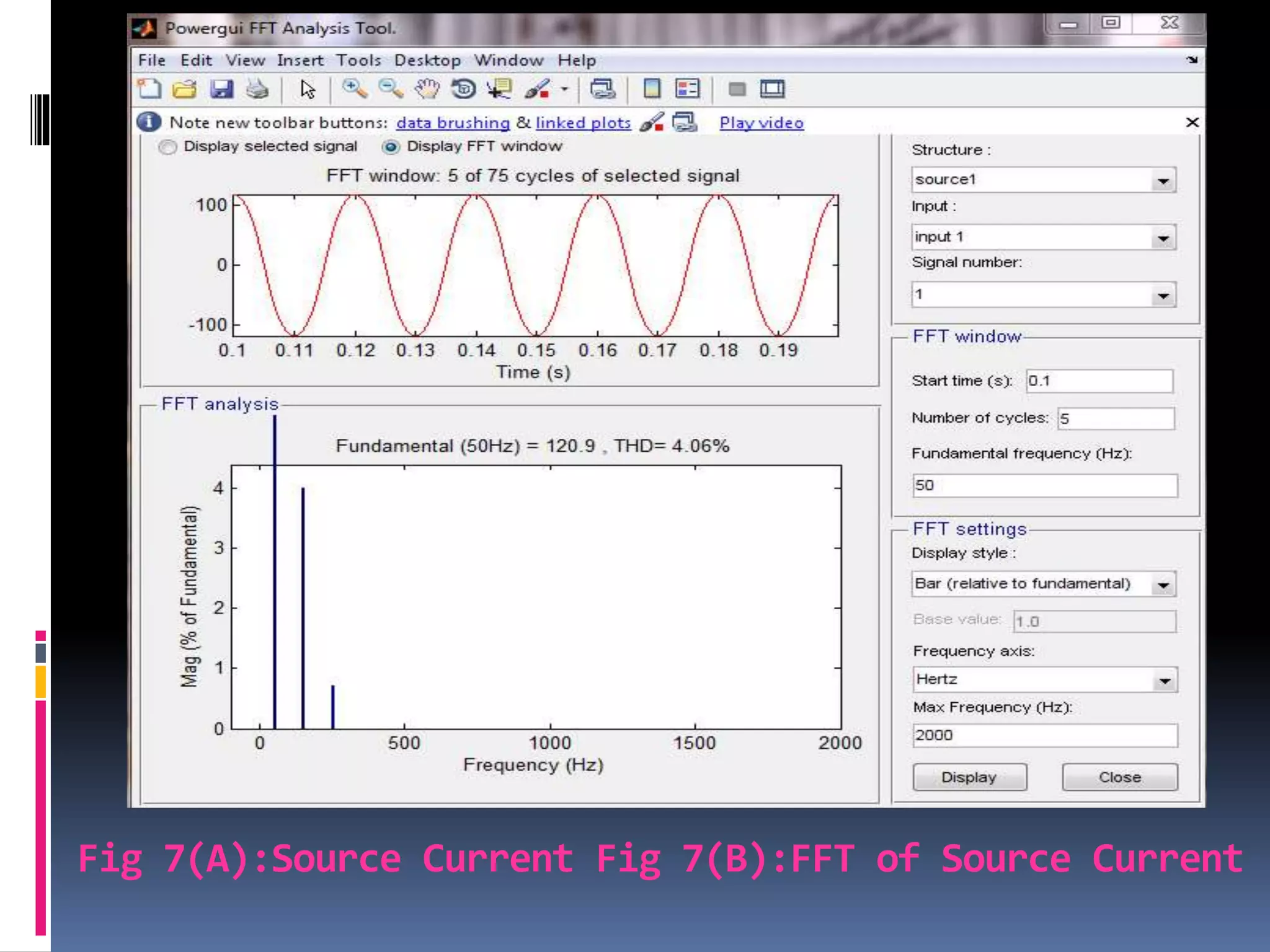
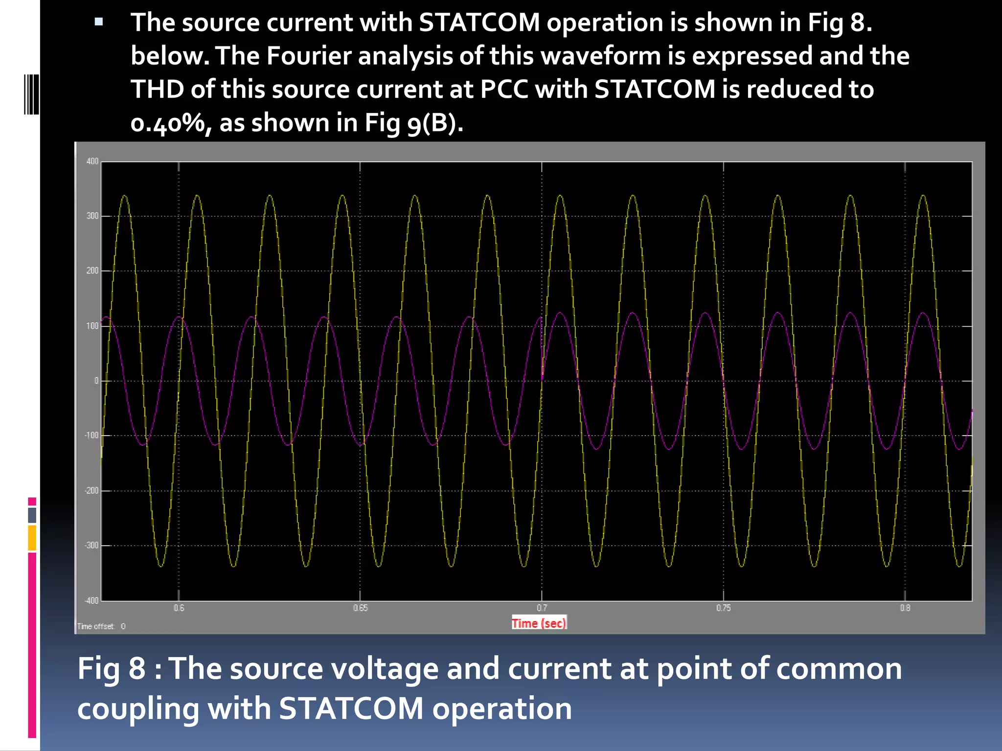
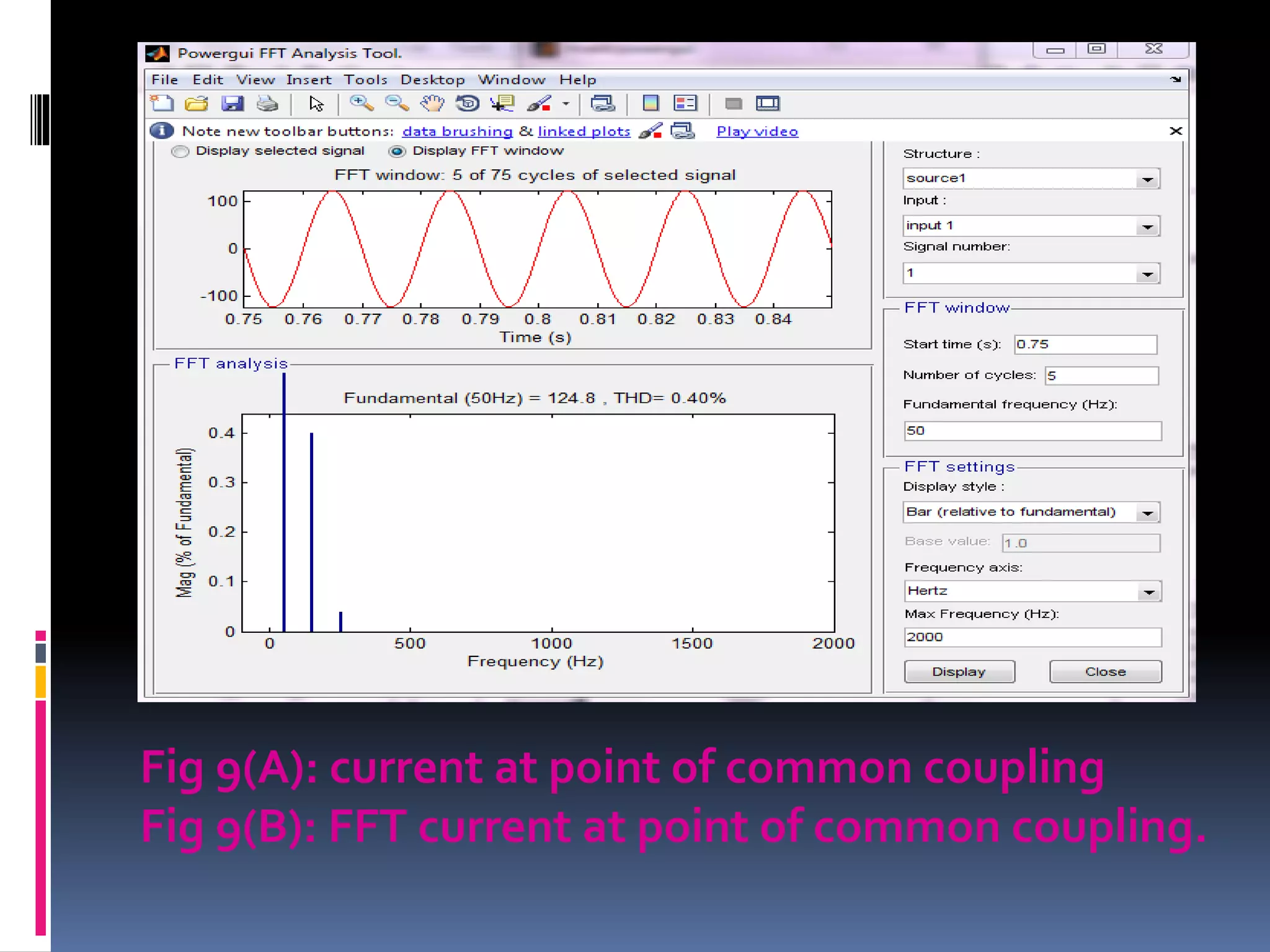
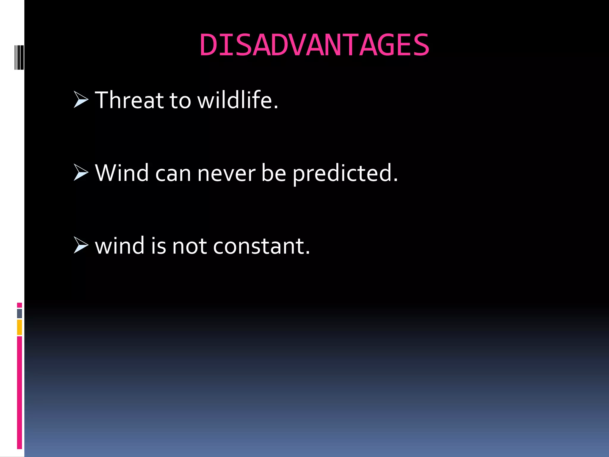
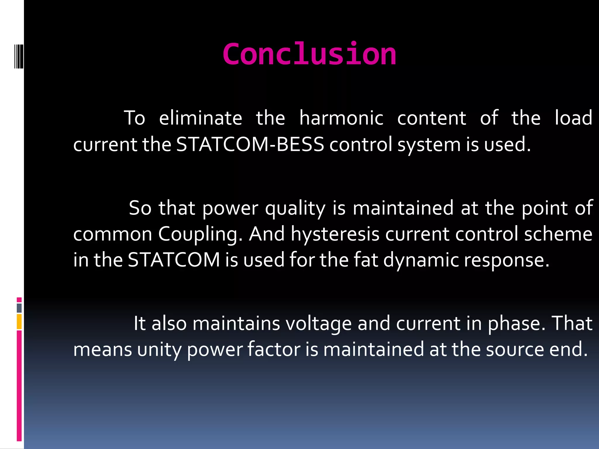
.
AMC ENGINEERING COLLEGE
DEPARTMENT OF ELECTRICAL AND ELECTRONICS ENGINEERING
BANGALORE - 560 083
PROJECT SEMINAR
ON
“POWER QUALITY IMPROVEMENT OF GRID CONNECTED WIND
ENERGY SYSTEM BY STATCOM-CONTROL SCHEME”
By
MR. SHIVARAJA D M
1AM13EPS13
UNDER THE GUIDANCE OF
MRS.S.SARANYA
Contents
1)Abstract.
2) Introduction.
3)Topology for power quality improvement.
4) Grid connected system for power quality
improvement
5) System Operation
6) Control Scheme
7) Simulation with results and power quality
improvement
8)conclusion
6) References
Abstract
 Injection of the wind power into an electric grid affects the
power quality.
 The active power, reactive power, variation of voltage, flicker,
harmonics distortion’s etc…
 Static Compensator (STATCOM) is connected at a point of
common coupling with BESS to mitigate the power quality
issues.
 BESS (Battery energy storage system)
 Simulated using MATLAB/SIMULINK in power system block set.
Introduction
 The integration of wind energy into existing power system
presents a technical challenges and that requires consideration of
 voltage regulation,
 stability,
 power quality problems.
 The power quality issues can be viewed with respect to the wind
G T & D network, such as voltage sag, swells, flickers, harmonics
etc.
 induction generator connected directly to grid system.
 In the event of increasing grid disturbance, a BESS(battery energy
storage system) for wind energy generating system is generally
required to compensate the fluctuation generated by wind turbine.
OBJECT:-
 The proposed STATCOM control scheme for grid connected wind
energy generation for power quality improvement has following
objectives.
• Unity power factor at the source side.
• Reactive power support from STATCOM to wind
Generator and Load.
• Simple bang-bang controller for STATCOM to achieve fast
dynamic response.
TOPOLOGY FOR POWER QUALITY IMPROVEMENT
 The STATCOM based current control voltage source
inverter injects the current into the grid in such a
way that the source current are harmonic free and
their phase-angle with respect to source voltage has
a desired value.
 The injected current will cancel out the reactive part
and harmonic part of the load and induction
generator current, thus it improves the power factor
and the power quality.
 The proposed grid connected system is
implemented for power quality improvement at
point of common coupling (PCC), as shown in Fig
below
Grid connected system for power
quality improvement
A) BESS-STATCOM:
 The battery energy storage system (BESS) is used as an
energy storage element for the purpose of voltage regulation.
 The BESS will naturally maintain dc capacitor voltage
constant and is best suited in STATCOM since it rapidly injects
or absorbed reactive power to stabilize the grid system.
 When power fluctuation occurs in the system, the BESS can
be used to level the power fluctuation by charging and
discharging operation. The battery is connected in parallel to
the dc capacitor of STATCOM.
B) System Operation:
 The shunt connected STATCOM with battery energy storage is
connected with the interface of the induction generator and
non-linear load at the PCC in the grid system.
 The STATCOM output is varied according to the controlled
strategy, so as to maintain the power quality norms in the grid
system
 A single STATCOM using insulated gate bipolar transistor is
proposed to have a reactive power support, to the induction
generator and to the nonlinear load in the grid system..
System Operation
CONTROL SCHEME:
 The control scheme approach is based on injecting the currents into
the grid using “bang-bang controller.”The controller uses a hysteresis
current controlled technique.
 Using such technique, the controller keeps the control system
variable between boundaries of hysteresis area and gives correct
switching signals for STATCOM.
 The control system scheme for generating the switching signals to
the STATCOM is shown in Fig.
SYSTEM PERFORMANCE
 The proposed control scheme is simulated using SIMULINK in power system
block set. The SIMULNK model library includes the models of converter, induction
generator, load Etc..It has been constructed for simulation. The system
parameters are given inTable 1 Below.
Sl.No Parameters Ratings
1. GridVoltage 3-phase, 415V, 50Hz
2. Induction Generator 3.35KVA, 415V, 50Hz, P=4
Rs=0.01Ω, Rr=0.015Ω, Ls=0.06H, Lr=0.06H
3. Inverter Parameters DC linkVoltage = 800V
DC link Capacitance = 100µF
Switching frequency = 2kHz
4. IGBT Rating CollectorVoltage = 1200V
Forward Current = 50A
GateVoltage = 20V
Power Dissipation = 310W
Simulation
STATCOM—Performance
 When STATCOM controller is made ON, without
change in any other load condition parameters, it
starts to mitigate the reactive demand as well as
harmonic current.
 The DC link voltage regulates the source current in
the grid system, so the DC link voltage is maintained
constant across the capacitor.
 The results of source current, load current are shown
in fig. 5(a) and 5(b) respectively. While the result of
injected current from STATCOM are shown in fig.5(c)
and the generated current from wind generator at
PCC are depicted in fig.5(d).
Fig. 5.(a) Source Current(b) Load Current.
(c) Inverter Injected Current
(d)Wind generator current.
Power Quality Improvement:
 It is observed that the source current on the grid is affected due to the
effects of nonlinear load and wind generator, thus purity of waveform
may be lost on both sides in the system.
 The source current without STATCOM operation is shown in Fig 6(B).
below.The Fourier analysis of this waveform is expressed and theTHD of
this source current at PCC without STATCOM is 4.06%, as shown in Fig
7(B).
Fig 7(A):Source Current Fig 7(B):FFT of Source Current
 The source current with STATCOM operation is shown in Fig 8.
below.The Fourier analysis of this waveform is expressed and the
THD of this source current at PCC with STATCOM is reduced to
0.40%, as shown in Fig 9(B).
Fig 8 :The source voltage and current at point of common
coupling with STATCOM operation
Fig 9(A): current at point of common coupling
Fig 9(B): FFT current at point of common coupling.
APPLICATIONS
 Power system voltage control application
 Large electric arc furnace installation
 Reactive power compensation application
 Railway or underground system with huge
load variation
ADVANTAGES
 The wind is free and with modern
technology it can be captured efficiently.
 Uninterrupted power supply.
 Wind power can go anywhere.
 Wind power is cost effective.
DISADVANTAGES
 Threat to wildlife.
 Wind can never be predicted.
 wind is not constant.
Conclusion
To eliminate the harmonic content of the load
current the STATCOM-BESS control system is used.
So that power quality is maintained at the point of
common Coupling. And hysteresis current control scheme
in the STATCOM is used for the fat dynamic response.
It also maintains voltage and current in phase. That
means unity power factor is maintained at the source end.
REFERENCES:-
[1] A. Sannino, “Global power systems for sustainable development,” in IEEE
General Meeting, Denver, CO,Jun. 2004.
[2]S. W. Mohod and M. V. Aware, “Power quality issues & it’s mitigation
technique in wind energy conversion,” in Proc. of IEEE Int. Conf. Quality
Power & Harmonic,Wollongong, Australia, 2008.
[3] S. W. Mohod and M. V. Aware, “Grid power quality with variable Speed
wind energy conversion,” in Proc. IEEE Int. Conf. Power Electronic Drives and
Energy System (PEDES), Delhi, Dec. 2006.
[4] R. S. Bhatia, S. P. Jain, D. K. Jain, and B. Singh, “Battery energy storage
system for power conditioning of renewable energy sources,” in Proc. Int.
Conf. Power Electron Drives System,Jan. 2006, vol. 1, pp.501-506.
[5] J. J. Gutierrez, J. Ruiz, L. Leturiondo, andA. Lazkano, “Flicker measurement
system for wind turbine certification,” IEEE Trans. Instrum. Meas., vol. 58,
no. 2, pp. 375–382, Feb. 2009.
FINAL PROJECT PPT

FINAL PROJECT PPT

  • 1.
    . AMC ENGINEERING COLLEGE DEPARTMENTOF ELECTRICAL AND ELECTRONICS ENGINEERING BANGALORE - 560 083 PROJECT SEMINAR ON “POWER QUALITY IMPROVEMENT OF GRID CONNECTED WIND ENERGY SYSTEM BY STATCOM-CONTROL SCHEME” By MR. SHIVARAJA D M 1AM13EPS13 UNDER THE GUIDANCE OF MRS.S.SARANYA
  • 2.
    Contents 1)Abstract. 2) Introduction. 3)Topology forpower quality improvement. 4) Grid connected system for power quality improvement 5) System Operation 6) Control Scheme 7) Simulation with results and power quality improvement 8)conclusion 6) References
  • 3.
    Abstract  Injection ofthe wind power into an electric grid affects the power quality.  The active power, reactive power, variation of voltage, flicker, harmonics distortion’s etc…  Static Compensator (STATCOM) is connected at a point of common coupling with BESS to mitigate the power quality issues.  BESS (Battery energy storage system)  Simulated using MATLAB/SIMULINK in power system block set.
  • 4.
    Introduction  The integrationof wind energy into existing power system presents a technical challenges and that requires consideration of  voltage regulation,  stability,  power quality problems.  The power quality issues can be viewed with respect to the wind G T & D network, such as voltage sag, swells, flickers, harmonics etc.  induction generator connected directly to grid system.  In the event of increasing grid disturbance, a BESS(battery energy storage system) for wind energy generating system is generally required to compensate the fluctuation generated by wind turbine.
  • 5.
    OBJECT:-  The proposedSTATCOM control scheme for grid connected wind energy generation for power quality improvement has following objectives. • Unity power factor at the source side. • Reactive power support from STATCOM to wind Generator and Load. • Simple bang-bang controller for STATCOM to achieve fast dynamic response.
  • 6.
    TOPOLOGY FOR POWERQUALITY IMPROVEMENT  The STATCOM based current control voltage source inverter injects the current into the grid in such a way that the source current are harmonic free and their phase-angle with respect to source voltage has a desired value.  The injected current will cancel out the reactive part and harmonic part of the load and induction generator current, thus it improves the power factor and the power quality.  The proposed grid connected system is implemented for power quality improvement at point of common coupling (PCC), as shown in Fig below
  • 7.
    Grid connected systemfor power quality improvement
  • 8.
    A) BESS-STATCOM:  Thebattery energy storage system (BESS) is used as an energy storage element for the purpose of voltage regulation.  The BESS will naturally maintain dc capacitor voltage constant and is best suited in STATCOM since it rapidly injects or absorbed reactive power to stabilize the grid system.  When power fluctuation occurs in the system, the BESS can be used to level the power fluctuation by charging and discharging operation. The battery is connected in parallel to the dc capacitor of STATCOM. B) System Operation:  The shunt connected STATCOM with battery energy storage is connected with the interface of the induction generator and non-linear load at the PCC in the grid system.  The STATCOM output is varied according to the controlled strategy, so as to maintain the power quality norms in the grid system  A single STATCOM using insulated gate bipolar transistor is proposed to have a reactive power support, to the induction generator and to the nonlinear load in the grid system..
  • 9.
  • 10.
    CONTROL SCHEME:  Thecontrol scheme approach is based on injecting the currents into the grid using “bang-bang controller.”The controller uses a hysteresis current controlled technique.  Using such technique, the controller keeps the control system variable between boundaries of hysteresis area and gives correct switching signals for STATCOM.  The control system scheme for generating the switching signals to the STATCOM is shown in Fig.
  • 11.
    SYSTEM PERFORMANCE  Theproposed control scheme is simulated using SIMULINK in power system block set. The SIMULNK model library includes the models of converter, induction generator, load Etc..It has been constructed for simulation. The system parameters are given inTable 1 Below. Sl.No Parameters Ratings 1. GridVoltage 3-phase, 415V, 50Hz 2. Induction Generator 3.35KVA, 415V, 50Hz, P=4 Rs=0.01Ω, Rr=0.015Ω, Ls=0.06H, Lr=0.06H 3. Inverter Parameters DC linkVoltage = 800V DC link Capacitance = 100µF Switching frequency = 2kHz 4. IGBT Rating CollectorVoltage = 1200V Forward Current = 50A GateVoltage = 20V Power Dissipation = 310W
  • 12.
  • 13.
    STATCOM—Performance  When STATCOMcontroller is made ON, without change in any other load condition parameters, it starts to mitigate the reactive demand as well as harmonic current.  The DC link voltage regulates the source current in the grid system, so the DC link voltage is maintained constant across the capacitor.  The results of source current, load current are shown in fig. 5(a) and 5(b) respectively. While the result of injected current from STATCOM are shown in fig.5(c) and the generated current from wind generator at PCC are depicted in fig.5(d).
  • 14.
    Fig. 5.(a) SourceCurrent(b) Load Current. (c) Inverter Injected Current (d)Wind generator current.
  • 15.
    Power Quality Improvement: It is observed that the source current on the grid is affected due to the effects of nonlinear load and wind generator, thus purity of waveform may be lost on both sides in the system.  The source current without STATCOM operation is shown in Fig 6(B). below.The Fourier analysis of this waveform is expressed and theTHD of this source current at PCC without STATCOM is 4.06%, as shown in Fig 7(B).
  • 16.
    Fig 7(A):Source CurrentFig 7(B):FFT of Source Current
  • 17.
     The sourcecurrent with STATCOM operation is shown in Fig 8. below.The Fourier analysis of this waveform is expressed and the THD of this source current at PCC with STATCOM is reduced to 0.40%, as shown in Fig 9(B). Fig 8 :The source voltage and current at point of common coupling with STATCOM operation
  • 18.
    Fig 9(A): currentat point of common coupling Fig 9(B): FFT current at point of common coupling.
  • 19.
    APPLICATIONS  Power systemvoltage control application  Large electric arc furnace installation  Reactive power compensation application  Railway or underground system with huge load variation
  • 20.
    ADVANTAGES  The windis free and with modern technology it can be captured efficiently.  Uninterrupted power supply.  Wind power can go anywhere.  Wind power is cost effective.
  • 21.
    DISADVANTAGES  Threat towildlife.  Wind can never be predicted.  wind is not constant.
  • 22.
    Conclusion To eliminate theharmonic content of the load current the STATCOM-BESS control system is used. So that power quality is maintained at the point of common Coupling. And hysteresis current control scheme in the STATCOM is used for the fat dynamic response. It also maintains voltage and current in phase. That means unity power factor is maintained at the source end.
  • 23.
    REFERENCES:- [1] A. Sannino,“Global power systems for sustainable development,” in IEEE General Meeting, Denver, CO,Jun. 2004. [2]S. W. Mohod and M. V. Aware, “Power quality issues & it’s mitigation technique in wind energy conversion,” in Proc. of IEEE Int. Conf. Quality Power & Harmonic,Wollongong, Australia, 2008. [3] S. W. Mohod and M. V. Aware, “Grid power quality with variable Speed wind energy conversion,” in Proc. IEEE Int. Conf. Power Electronic Drives and Energy System (PEDES), Delhi, Dec. 2006. [4] R. S. Bhatia, S. P. Jain, D. K. Jain, and B. Singh, “Battery energy storage system for power conditioning of renewable energy sources,” in Proc. Int. Conf. Power Electron Drives System,Jan. 2006, vol. 1, pp.501-506. [5] J. J. Gutierrez, J. Ruiz, L. Leturiondo, andA. Lazkano, “Flicker measurement system for wind turbine certification,” IEEE Trans. Instrum. Meas., vol. 58, no. 2, pp. 375–382, Feb. 2009.