This document summarizes the development of a suspension system for a Formula Student race car designed by a group of students at Plymouth University. It describes the initial concept of a double wishbone suspension and how aerodynamic limitations led to changes. Calculations, CAD modeling, FEA analysis, and MATLAB simulations were used in the design process. Several iterations optimized aspects of the suspension such as material selection, component geometry, and manufacturing methods. A final cost analysis found the designed suspension system would meet requirements and be viable for the ongoing student race car project.


![Group F1 10
Failure of components
o A critical failure that could cause injury, event disqualification, or
damage to the University’s reputation. Considered unlikely due to
thorough analysis, as well as sufficient testing before event occurs.
The full FMECA, containing all potential failure modes, can be viewed in the
calculations spreadsheet, FMECA worksheet. A number of mitigating actions were
taken such as sufficient calculations/testing, and ensuring reputable suppliers for
parts, to reduce possible failure modes. As the severity of the failure modes will
remain, the frequency at which they may occur was addressed.
4.2. Calculations
4.2.1. Forces
The first place to start was to calculate the centre of gravity of the car in order to
determine the weight transfer under dynamic conditions. This was done by
gathering x, y and z coordinates, and the mass values for the main components.
Equation 1 was used to find the centre of gravity in the y direction:
𝐶𝐺 𝑦 =
𝑚 𝑐ℎ𝑎𝑠𝑠𝑖𝑠 ∗ 𝑦𝑐ℎ𝑎𝑠𝑠𝑖𝑠 + 𝑚 𝑒𝑛𝑔𝑖𝑛𝑒 ∗ 𝑦 𝑒𝑛𝑔𝑖𝑛𝑒 + 𝑚 𝑑𝑟𝑖𝑣𝑒𝑟 ∗ 𝑦 𝑑𝑟𝑖𝑣𝑒𝑟 + 𝑚 𝑓𝑢𝑒𝑙 𝑡𝑎𝑛𝑘 ∗ 𝑦𝑓𝑢𝑒𝑙 𝑡𝑎𝑛𝑘
𝑚 𝑐ℎ𝑎𝑠𝑠𝑖𝑠 + 𝑚 𝑒𝑛𝑔𝑖𝑛𝑒 + 𝑚 𝑑𝑟𝑖𝑣𝑒𝑟 + 𝑚 𝑓𝑢𝑒𝑙 𝑡𝑎𝑛𝑘
. . (1)
The process was repeated for the z coordinates of each component. It was assumed
that the x coordinate centre of gravity would lie at the car centreline. The minimum
track width to compete in the static 60ͦ test was calculated using Equation 2:
𝑊𝑡𝑟𝑎𝑐𝑘 𝑚𝑖𝑛 = (2 ∗ 𝐶𝐺 𝑦 ∗ tan(60)) − 𝑊𝑡𝑦𝑟𝑒 = 2 ∗ 0.325 ∗ tan(60) − 0.25 = 0.876 (2)
Using the centre of gravity, the dynamic forces were calculated, starting with the
linear forces. Using performance data for the AG proposed Honda CBR 600 engine,
and a mass conversion, an acceleration rate of 1.96 m/s2 was obtained. The vertical
forces acting on the front and rear axles were then calculated using Equations 3
and 4:
𝐹𝑓 =
𝐶𝐺𝑟
𝐿
∗ 𝑚 ∗ 𝑔 −
𝐶𝐺 𝑦
𝐿
𝑚 ∗ 𝑎 = 1083 𝑁 (3)
𝐹𝑟 =
𝐶𝐺𝑟
𝐿
∗ 𝑚 ∗ 𝑔 +
𝐶𝐺 𝑦
𝐿
𝑚 ∗ 𝑎 = 2616 𝑁 (4)
The maximum deceleration rate was calculated, assuming that braking causes a
complete weight transfer to the front wheels, to the point the wheels start skidding.
𝑎−1
=
𝜇 ∗ 𝑊
𝑚 𝑐
=
0.7 ∗ 3698.7[𝑁]
377[𝑘𝑔]
= 6.9 [
𝑚
𝑠2
] (5)
The 6.9m/s2 deceleration rate equates to 0.7g. However, this value is widely taken
to be 1.5g to act as a factor of safety. The vertical forces obtained were: 2268.7 N](https://image.slidesharecdn.com/5561d9e5-3201-4405-83d6-12636e545a4d-151213224111/85/Deadline3_GroupF1_Design_Report-11-320.jpg)
![Group F1 11
on the front, and 1429.7 N on the rear.
Using the tightest corner of 4.5m radius, the lateral forces at each wheel were
calculated for a left hand turn, using Equations 6-8:
𝐹𝑐 =
𝑚 ∗ 𝑣2
𝑟
= 8377.8 𝑁 (6)
𝐹𝑓𝑟 = 0.5 ∗ (𝑚 ∗ 𝑔 + (𝐹𝑐 ∗
𝐶𝐺 𝑦
0.5 ∗ 𝐿
)) ∗ 𝐶𝐺𝑟 = 1951 𝑁 (7)
𝐹𝑟𝑟 = 0.5 ∗ (𝑚 ∗ 𝑔 + (𝐹𝑐 ∗
𝐶𝐺 𝑦
0.5 ∗ 𝐿
)) ∗ 𝐶𝐺𝑧 = 3953 𝑁 (8)
(Bansal, 2005)
4.2.2. Ackerman
Ackerman steering theory was used to ensure the wheel
lock could accommodate the sharpest turn; it was
important to determine turning calculations that would
give a specified wheel lock, dependant on the wheel
base.
Using the AG geometry, the turning dimensions could be
calculated for the wheel base of the final design. Using
Equation 9 the wheel lock was calculated:
𝜃𝑜 = 𝑡𝑎𝑛−1
(
1
1
tan(𝜃𝑖)
+
𝑊𝑡𝑟𝑎𝑐𝑘
𝑊𝑙𝑒𝑛𝑔𝑡ℎ
) = 22° (9)
Equations 10-11 were used to calculate
the radial distance to the rear and to the
centre of gravity could be calculated:
𝐿 𝑟 =
𝑊 𝑙𝑒𝑛𝑔𝑡ℎ
tan(𝜃 𝑖)
+
𝑊 𝑡𝑟𝑎𝑐𝑘
2
= 3.68 𝑚 (10)
𝐿 𝐶𝐺 = √𝐿 𝑟
2 + 𝐶𝐺𝑟
2 = 3.73 𝑚 (11)
Utilising a parametric spreadsheet,
different track and wheelbase lengths
could be used to calculate the outer angle
necessary.
20
30
40
1 1.5 2 2.5
Insidewheellock[°]
Wheelbase [m]
Wheel Lock Requirement
Figure 6: Graph showing required
steering lock
Figure 5: Ackerman theory
(Popa, 2005)](https://image.slidesharecdn.com/5561d9e5-3201-4405-83d6-12636e545a4d-151213224111/85/Deadline3_GroupF1_Design_Report-12-320.jpg)
![Group F1 12
4.2.3. Spring Rate Selection
FSAE rules state the maximum wheel travel must be limited to 25.4mm jounce and
rebound. The maximum load at any one wheel is less than double the force due to
the cars self-weight. Thus, the spring rates (SR) have been selected to sit the car at
25.4mm compression under static load. The wheel rate (WR) was determined using
half the static load on one axle.
𝑊𝑅 =
0.5 ∗ 𝑊𝑟
𝑡 𝑚𝑎𝑥
=
0.5 ∗ 2476[𝑁]
25.4[𝑚𝑚]
= 48.7 [
𝑁
𝑚𝑚
] (12)
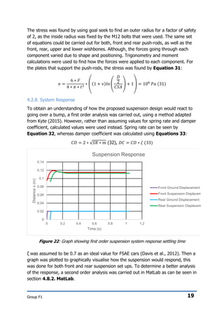
The motion ratio (MR) is the ratio of shock, or in this designs case, push-rod
mounting position (D1) to the lower wishbone hub mounting (D2). The angle
correction factor (ACF) relates the shock mounting angle to the vertical, as labelled
in Figure 7.
𝑀𝑅 =
𝐷1
𝐷2
=
267.3[𝑚𝑚]
346.1[𝑚𝑚]
= 0.77 (13)
𝐴𝐶𝐹 = cos(𝐴) = cos(35.4˚) = 0.815 (14)
𝑆𝑅 =
𝑊𝑅
𝑀𝑅2 ∗ 𝐴𝐶𝐹
=
48.7 [
𝑁
𝑚𝑚
]
0.772 ∗ 0.815
= 100.8 [
𝑁
𝑚𝑚
] (15)
The procedure carried out for the front suspension gave a spring rate of 48.9N/mm.
Combining jounce and rebound, the total spring travel distance is 50.8mm,
Equation 16 was used to determine how much travel is used by the front and rear
suspension under dynamic loadings. W reflects the vertical force at the rear right
hand wheel going around a left hand corner, at full acceleration. This load case is
the maximum that could occur at a rear wheel and still within the design limits.
𝑡 𝑢𝑠𝑒𝑑 =
𝑊
𝑆𝑅 ∗ 𝑀𝑅2 ∗ 𝐴𝐶𝐹
=
2454.6[𝑁]
100.8 [
𝑁
𝑚𝑚
] ∗ 0.772 ∗ 0.815
= 50.3[𝑚𝑚](16)
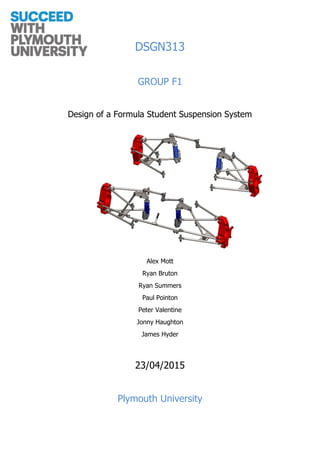
4.2.4. Track Width
Equation 17 determines the maximum speed that the car could go around a corner,
based on the first instant the inside wheels exert zero force on the track.
𝑣 𝑚𝑎𝑥 = √
𝑟 ∗ 𝑁𝑔 ∗ 𝑔 ∗ 𝑊𝑡𝑟𝑎𝑐𝑘
2 ∗ 𝐶𝐺 𝑦
(17)
Figure 7: Motion ratio and mounting angle](https://image.slidesharecdn.com/5561d9e5-3201-4405-83d6-12636e545a4d-151213224111/85/Deadline3_GroupF1_Design_Report-13-320.jpg)
![Group F1 13
Figure 9: Showing different suspension
geometries
Ng is an assumed value of 1.7g, which is the amount of g’s the car can withstand
through cornering. This was based on FSAE stating the static 60° tilt roughly
replicated 1.7g cornering (SAE rules, 2014).
4.2.5. Suspension Geometry
Theander (2004) gives guidelines for suspension geometries in accordance with
suspension theory and previous FSAE car data as listed below, and was considered
when designing the suspension geometry. The numbers correlate to Figure 9.
Kingpin inclination: 0˚ to 8˚ (1)
Scrub radius: 0mm to 10mm (2)
Caster angle: 3˚ to 7˚ (5)
Static camber: 0˚ to -4˚ (3)
Roll centre height: 0mm to 50mm
Toe: Minimise bump steer as much as
possible (4)
The spreadsheet used integrated trigonometry,
Pythagoras’ theorem and the current fixing points
at the hub and chassis to determine the wishbone
and pushrod dimensions as well as scrub radius,
kingpin inclination, track width change, toe angle,
and camber angle throughout compression.
The existing concept used wishbones with mountings either side of the hub with no
adjustment for camber or toe, as shown in Figure 10. The proposed design shown
Figure 8: Graph showing effects of track width on cornering speed
0
5
10
15
20
25
30
0 5 10 15 20 25
MaximumCorneringspeed[m/s]
Cornering Radius [m]
1.4m
1.1m
1.2m
1.3m](https://image.slidesharecdn.com/5561d9e5-3201-4405-83d6-12636e545a4d-151213224111/85/Deadline3_GroupF1_Design_Report-14-320.jpg)

![Group F1 15
The front toe arm is fixed between the hub and steering rack, as shown by the AG
concept in Figure 14. The fixing points at the steering rack caused substantial
bump steer in excess of 7°, and the steering rack location in the car meant the
steering column had to pass between the pedals, making them hard to operate in
race conditions. Iterating through for different steering rack fixing locations it was
found, moving the steering rack up to the next chassis member, as shown in Figure
15. This reduced the amount of bump steer to within 2° total change, also moving
the steering column so that it would not hinder pedal operation.
Figure 14: Steering system showing
interaction with steering arm.
Figure 15: Proposed steering arm position.
4.2.5.2. Camber angle
Camber angle dictates the amount of tyre contact
with the ground. Negative camber as shown in
Figure 16 will decrease straight line grip but
increase cornering grip as it counteracts tyre roll
generated by centrifugal forces when cornering. The
following formula can be used to approximate the
camber angle (θC) required for the wheels to remain
flat with the ground.
𝜃 𝐶 = sin−1
(
2 ∗ 𝑡 𝑐𝑜𝑚𝑝𝑟𝑒𝑠𝑠𝑖𝑜𝑛
𝑇𝑊
) = sin−1
(
2 ∗ 25.4[𝑚𝑚]
1260[𝑚𝑚]
) = 2.31˚(18)
The graph in Figure 17 represents the above equation plotted for 25.4mm jounce
and rebound. The optimum camber angle was set by finding the wheel displacement
(trc) caused by the maximum cornering load (Wfr), using Equations 19-20, and
extrapolating the camber angle from Figure 17.
𝑊𝑅 𝑐 =
0.5 ∗ 𝑊𝑓𝑟
𝑡 𝑚𝑎𝑥
=
0.5 ∗ 3952.5[𝑁]
25.4[𝑚𝑚]
= 77.8 [
𝑁
𝑚𝑚
] (19)
Steering
Column
Figure 16: Positive vs negative
camber (Blueriverfleet, 2015)
Steering
Column](https://image.slidesharecdn.com/5561d9e5-3201-4405-83d6-12636e545a4d-151213224111/85/Deadline3_GroupF1_Design_Report-16-320.jpg)
![Group F1 16
𝑡𝑓𝑐 =
𝑊𝑅 𝑐 ∗ 𝑡 𝑚𝑎𝑥
𝑊𝑅
=
77.8 [
𝑁
𝑚𝑚
] ∗ 25.4[𝑚𝑚]
48.7 [
𝑁
𝑚𝑚
]
= 40.5[𝑚𝑚](20)
At 40.5mm the camber angle for maximum tyre contact is -1.36˚. Based on this
value a camber graph shown in Figure 18 has been produced, the total change in
camber is significantly lower than if it were left at 0˚.
Figure 17. Camber angle for maximum tyre
contact.
Figure 18. Camper through compression
with optimised static angle.
4.2.5.3. Kingpin inclination and scrub radius
The kingpin inclination and camber angle are the only two properties able to alter
the scrub radius, which should be kept between 0 and 10mm to prevent torque steer
(Theander, 2004). An effect that occurs if forces through braking or accelerating are
not the same either side of the car, such as in the event of cornering, a higher scrub
radius will cause greater torque steer.
The kingpin inclination does not change through compression as it is fixed in the
geometry of the hub. Its primary function is to aid the steering’s return to neutral as
the wheel hub rotates about the upper and lower mounting points that form the
kingpin inclination. If the kingpin inclination is too large, it will cause heavy steering
that tries to snap back to neutral. The kingpin also affects the scrub radius, the
larger the kingpin, the lower the scrub radius.
Initially the scrub radius was close to 40mm, as such the kingpin was set to the
maximum value of 8˚. Further alterations, which are covered in Section 4.4. Re-
iteration, Alterations & Design Development, had to be made to the hub and
brake calliper to reduce this value to 11.3mm. This is still larger than ideal, but a
compromise to prevent increasing kingpin inclination or camber angle further.](https://image.slidesharecdn.com/5561d9e5-3201-4405-83d6-12636e545a4d-151213224111/85/Deadline3_GroupF1_Design_Report-17-320.jpg)


![Group F1 47
7. References
2015 Formula SAE Rules. (2014). 1st ed. [ebook] SAE International. Available at:
http://students.sae.org/cds/formulaseries/rules/2015-16_fsae_rules.pdf
Aurorabearing.com, (2015). FAQs - Aurora Bearing Rod Ends, Spherical Bearings &
Bushings. [online] Available at: http://www.aurorabearing.com/technical-faqs.html
[Accessed 2 Apr. 2015].
Bansal, R (2005) A Textbook of Theory of Machines, USA: Laxmi Publications.
Blueriverfleet.com, (2015). Blue River Fleet Service - Shelbyville, IN. [online]
Available at: http://www.blueriverfleet.com/alignment.htm [Accessed 20 Apr. 2015].
Buy Metal Online (2015) 6.0mm / 2 SWG (0.236") - HOT ROLLED, Available
at:http://www.buymetalonline.co.uk/buy-steel-sheet/hot-rolled/6.0mm-2-swg-hot-
rolled.html(Accessed: 16th April 2015).
Carltedt, T. (2014) Sand Casting vs Investment Casting, Available
at: http://info.cpm-industries.com/blog/bid/178170/Sand-Casting-vs-Investment-
Casting (Accessed: 13th April 2015).
Custompart.net (2009) Cost Estimator, Available
at:http://www.custompartnet.com/estimate/sand-casting/ (Accessed: 13th April
2015).
Davis, W, Carney, K, Leith, J, Kirschner, A, Piccioli, D (2012) DESIGN AND
OPTIMIZATION OF A FORMULA SAE RACECAR , Worcester: WORCESTER
POLYTECHNIC INSTITUTE .
Drivealuminum.org, (2015). Sustainability — Drive Aluminum. [online] Available at:
http://www.drivealuminum.org/aluminum-advantages/sustainability [Accessed 20
Apr. 2015].
EngineeringToolbox,. 'Threads - Metric ISO 724'. Engineeringtoolbox.com. N.p.,
2015. Web. 21 Apr. 2015.
Epa.gov, (2015). Life Cycle Assessment (LCA) | Sustainable Technology Research |
US EPA. [online] Available at: http://www.epa.gov/nrmrl/std/lca/lca.html#define
[Accessed 17 Apr. 2015].
Formula1-dictionary, (2015). 'Pushrod-Pullrod'. Web. 7 Apr. 2015.
Granta, Design. CES Edupack. Granta Design, 2015. Print.
Hu, H. (2014) Forged Steel Square - Flat Bar, Available
at:http://www.fuhongsteel.com/forged-steel-square-flat-bar-
2218113.html (Accessed: 31st March 2015).
Kaz Technologies (2015) FSAE Shocks, Available](https://image.slidesharecdn.com/5561d9e5-3201-4405-83d6-12636e545a4d-151213224111/85/Deadline3_GroupF1_Design_Report-48-320.jpg)
![Group F1 48
at:http://www.kaztechnologies.com/fsae/shocks/ (Accessed: 08/04/15).
KMT Waterjet (2015) Metal Cutting, Available at: http://www.kmtwaterjet.com/kmt-
metal-cutting.aspx (Accessed: 16th April 2015).
Kyte, A. (2015). Using Excel Macros.
Lee, H (2014) Mechanics of Materials with SolidWorks Simulation 2014, USA: SDC
Publications.
Nelson, J (2009) Single Vs Double Adjustable Shocks, Available
at:http://www.superchevy.com/how-to/chassis-suspension/0904chp-single-vs-
double-adjustable-varishocks-pros-cons/ (Accessed: 10/04/15).
Norton Aluminium (2009) LM25 (EN 1706 AC-42000) - Aluminium Casting
Alloy,Available at: http://www.nortal.co.uk/LM25/ (Accessed: 16th April 2015).
Popa, C.E. (2005) Steering System and suspension design for 2005 formula SAE-A
racer car, Australia: University of Southern Queensland.
QA1 (2015) Street performance & racing spring rate tech, Available
at:http://www.qa1.net/tech/street-performance-racing-spring-rate-tech (Accessed:
2nd February 2015).
springfixlinkages,. 'Low Cost Rod End - Male'. springfixlinkages. N.p., 2015. Web. 19
Apr. 2015.
Steel Tubes Direct (2015) Round Cold Drawn Seamless Steel Tube | Cold Drawn
Tubes, Available at: http://www.steeltubedirect.co.uk/products/Round-Cold-Drawn-
Seamless-Steel-Tube-Cold-Drawn-Tubes/P100004 (Accessed: 31st March 2015).
Tata Steel Construction, (2015). The carbon footprint of steel | Tata Steel
Construction. [online] Available at:
http://www.tatasteelconstruction.com/en/sustainability/carbon-and-steel [Accessed
17 Apr. 2015].
Tata Steel Europe (2014) Steels for the Aerospace Industry, Available
at:http://www.tatasteeleurope.com/file_source/StaticFiles/Speciality/publications/Tat
a_Steel_Aerospace_Pocket_Book_Aug12.pdf(Accessed: 31st March 2015).
Technical F1 Dictionary (2014) Roll centre, Available at: http://www.formula1-
dictionary.net/roll_center.html (Accessed: 17th April 2015).
Tenaris (2015) Cold drawn seamless steel tubes for mechanical
applications, Available
at: http://www.tenaris.com/shared/documents/files/CB32.pdf (Accessed: 31st March
2015).
Theander, A (2004) Design of a Suspension for a Formula Student Race Car, Sweden:
Aeronautical and Vehicle Engineering Royal Institute of Technology.](https://image.slidesharecdn.com/5561d9e5-3201-4405-83d6-12636e545a4d-151213224111/85/Deadline3_GroupF1_Design_Report-49-320.jpg)


