Downloaded 1,320 times

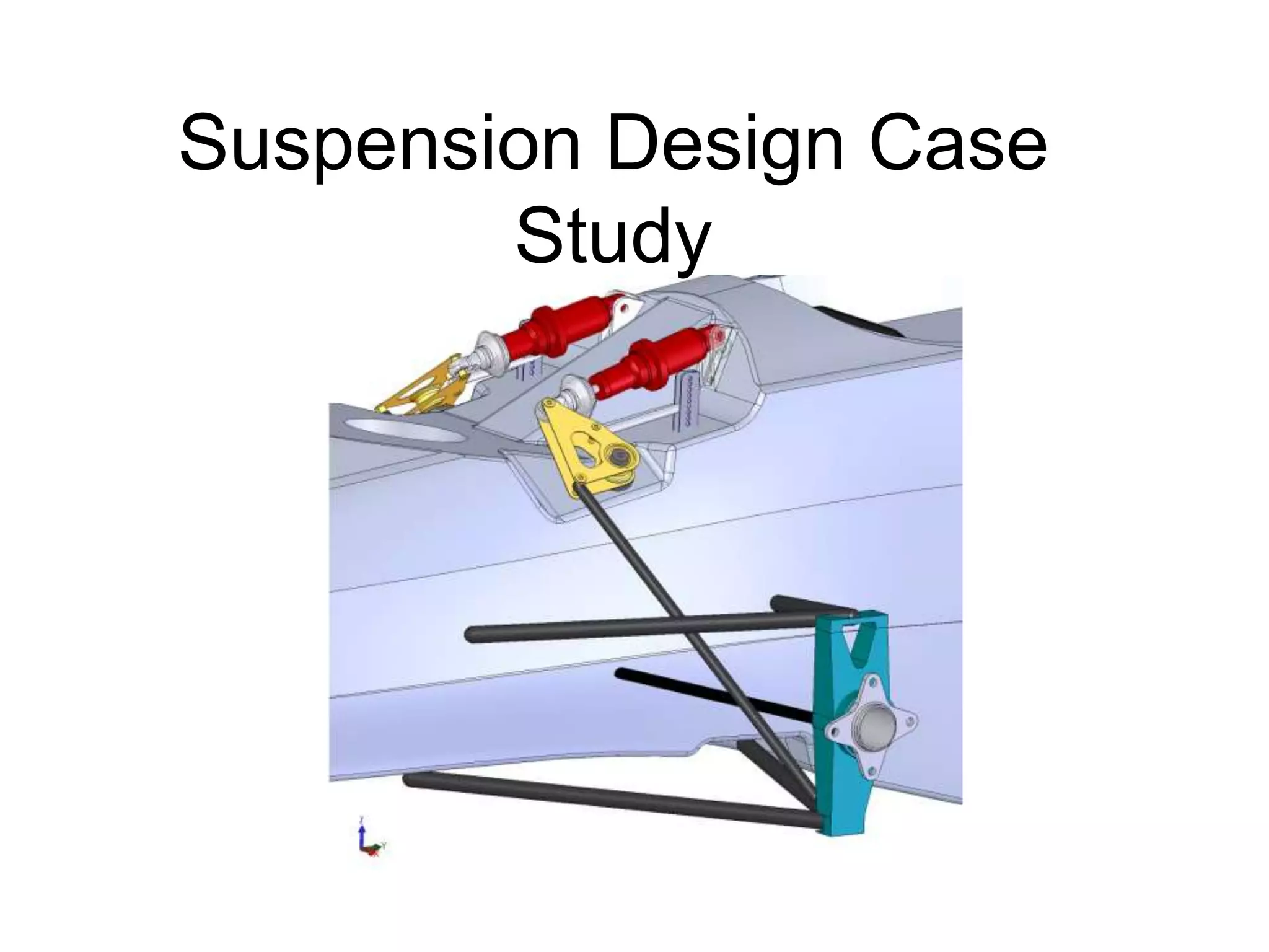
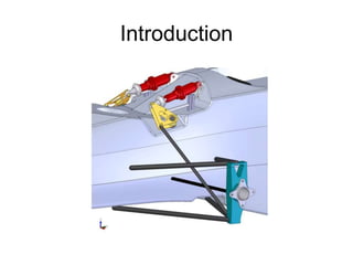
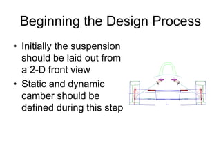
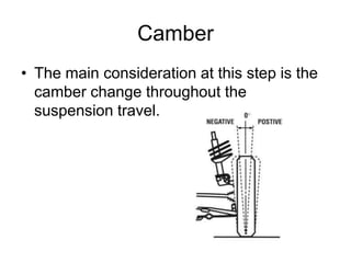

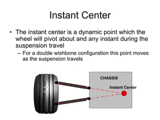
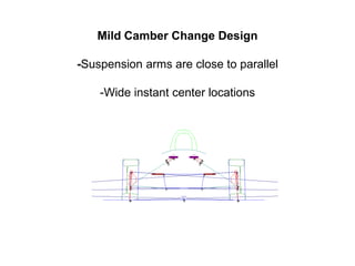
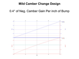
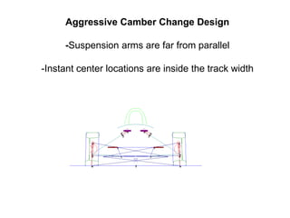
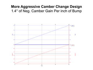
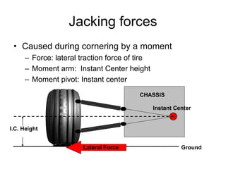
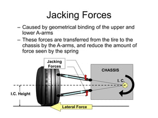
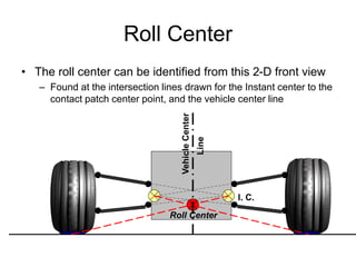
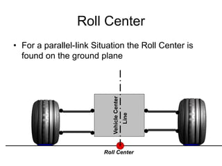
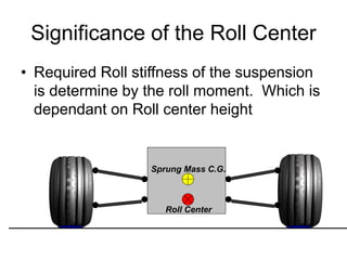
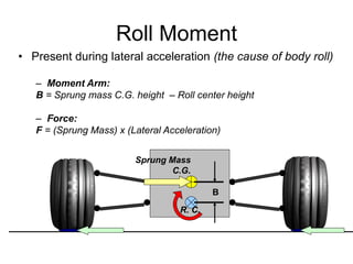
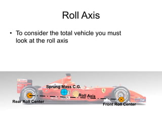
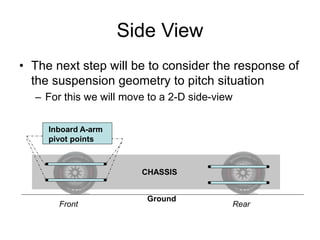
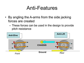

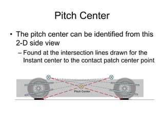
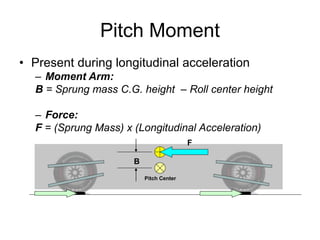

The document provides an overview of suspension design considerations for a formula-style racecar. Key points include: - The suspension needs enough travel while minimizing body roll for tight courses. Components like A-arms, uprights, and coil-overs are discussed. - Camber change throughout suspension travel must be optimized for cornering grip vs. braking/acceleration. Instant center movement affects jacking forces. - Roll center height influences required roll stiffness. Angling A-arms can provide anti-dive and anti-squat to control pitch. - Views from the front and side are needed to design camber, roll center, and pitch center locations.


