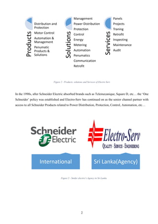
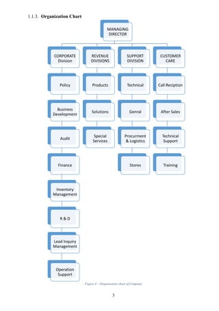
(RIA) Call Girls Bhosari ( 7001035870 ) HI-Fi Pune Escorts Service
Naita training report Electro serv
1. National Apprentice & Industrial Training
Authority
Report on Industrial Training
At
Electro-Serv (PVT) LTD
Nugegoda
University Collage of Rathmalana
Rathmalana
Name : L.V.P.V. Madushanka
Student Number : RT/ECT/16/017
Course : HND in Electrical Technology
Field : Electrical
Period : 06 months
2. ii
ACKNOWLEDGMENT
Firstly, I would like to extend my sincere thanks to all of them helping to successful for
this Training period. It would not have been possible without the kind support and help of many
individuals and organizations and I would like to take this opportunity to thank to the Our Lecture and
student coordinator H K A P Yasodara, Industrial training Division of University collage of Rathmalana
& Industrial Training Authority (NAITA) for making this training program a success and giving me this
opportunity to gain the in plant traineeships in Electro Serv (PVT) LTD.
I am highly indebted to Rathmalana Workshop manager Mr. Amila of the Electro Serv
(Pvt) Lt. His guidance and constant supervision as well as for providing necessary information during the
6 month training period. And Site engineer Mr.Dhanushka and Head of Project & Panel Division Mr.Upul
Premakumara who provide facilities, coordination and assessment which help me to develop skills and motor
controlling knowledge.
I would like to thank Technical Coordinator, Site Engineers and other Technical Staff
provide supportive information and advice to perform the task successfully. And who support directly
and indirectly to complete the task. Finally, an honorable mention goes to Technician supervisor
Mr.Kalum, my family, my colleagues and seniors and any other who helped me for their guidance and
support in many ways during the training period.
L.V.P.V.Madushanka.
Higher National Diploma,
Department of Electrical Technology.
University Collage of Rathmalana.
3. iii
PREFACE
The report was made at the end of my industrial training period. In my industrial training
period as an Electrical technology higher national diploma holder, I had my industrial training at Electro
Serv (Pvt) Lt for 24 weeks duration starting from 16th
October 2017 to 16th
April 2018.
The report consists of 3 major chapters. First chapter mainly includes Information about
Training Establishment. Then First chapter describes main functions, Organizational chart, Nature of
business and Vision, Mission, Management style, Present Performance and safety practices.
The second chapter mainly describes training experience at the Training Establishment, it contains
about the technical experience and provides the information about the projects I’ve done during the
training period, in Head office, workshop and site area.
The third or final chapter includes the conclusion of the report. This conclusion include an
assessment on the current Industrial Program.
4. iv
Contents
1. INTRODUCTION ..............................................................................................................................1
1.1. Introduction about the Training Establishment............................................................................1
1.1.1. About Electro Serv Private Limited .....................................................................................1
1.1.2. Nature of business.................................................................................................................1
1.1.3. Organization Chart................................................................................................................3
1.2. Co-Operate Plan...........................................................................................................................4
1.2.1. Vision & Mission..................................................................................................................4
1.2.1.1. Vision................................................................................................................................4
1.2.1.2. Mission..............................................................................................................................4
1.2.2. Management Style ................................................................................................................5
1.2.3. Recruitment Procedure .........................................................................................................5
1.2.4. Leave.....................................................................................................................................5
1.2.5. EPF and ETF.........................................................................................................................6
1.2.6. Welfare Activities.................................................................................................................6
1.3. Safety Practices............................................................................................................................7
1.3.1. Electrical Safety clothing......................................................................................................8
1.3.2. Electrical safety signs and symbols ......................................................................................9
2. TRAINING EXPERIENCE..............................................................................................................10
2.1. Design Section ...........................................................................................................................11
2.2. Plan and inspection section........................................................................................................14
2.2.1. Simple control & power circuit for power panel board......................................................14
2.2.2. Advance control circuit for power panel board in industrial..............................................14
2.2.3. Automatic star delta control & power circuit for large scale three phase motor................14
2.2.4. Automatic power factor correction circuit in industrial .....................................................14
2.3. Component & Store section.......................................................................................................19
2.3.1. Panel Board.........................................................................................................................19
2.3.2. Circuit Beaker.....................................................................................................................21
2.3.3. Earth Leakage Relay...........................................................................................................22
2.3.4. Surge protection device / Surge Diverter............................................................................25
2.3.5. Panel Voltmeter ..................................................................................................................27
2.3.6. Panel Ammeter ...................................................................................................................28
2.3.7. Panel Power Analyzer.........................................................................................................29
2.3.8. Contactor.............................................................................................................................31
2.3.9. Phase Failure Relay (PFR)..................................................................................................33
2.3.10. Variable Frequency Drive...............................................................................................34
2.3.11. Power Factor Regulator ..................................................................................................39
5. v
2.4. Wiring Section ...........................................................................................................................42
2.5. Testing Section...........................................................................................................................46
2.5.1. Continuity testing................................................................................................................46
2.5.2. Insulation Testing ...............................................................................................................47
2.5.3. Polarity testing....................................................................................................................48
2.5.4. Earth fault loop impedance (ELI) testing ...........................................................................48
3. CONCLUSION TO THE REPOT....................................................................................................49
4. REFERENCE ...................................................................................................................................50
Figure 1 - Official logo of Electro Serv (PVT) LTD..................................................................................1
Figure 2 - Products, solutions and Services of Electro Serv.......................................................................2
Figure 3 - Snider electric's Agency in Sri Lanka........................................................................................2
Figure 4 – Organization chart of Company................................................................................................3
Figure 5 - Chat of Calculation of EPF........................................................................................................6
Figure 6 - Example of Safety practices.......................................................................................................7
Figure 7 - Earth symbol ..............................................................................................................................7
Figure 8 - Safety practices ..........................................................................................................................7
Figure 9 - Safety clothing ...........................................................................................................................8
Figure 10 - Chart of the panel board type.................................................................................................10
Figure 11 - Flow chart of the how to select cable size .............................................................................11
Figure 12 - Example of enginner's design section....................................................................................12
Figure 13 - Factors of selection cable size................................................................................................12
Figure 14 - Standard procedure of selection cable size ............................................................................13
Figure 15 - Drawing of Simple control & power circuit ..........................................................................15
Figure 16 - Drawing of Advance control circuit for power panel board in industrial..............................16
Figure 17 - Drawing of Automatic star delta control & power circuit for large scale three phase motor 17
Figure 18 - Drawing of Automatic power factor correction circuit in industrial .....................................18
Figure 19 - Wall mounting Enclosure ......................................................................................................19
Figure 20 - Floor Mounting Enclosure.....................................................................................................20
Figure 21 - Circuit Breaker.......................................................................................................................21
Figure 22 - Chart of circuit breaker type ..................................................................................................21
Figure 23 - EFR & CBCT.........................................................................................................................22
Figure 24 - Function and Characteristics of ELR.....................................................................................23
Figure 25 - Shunt release (MX)................................................................................................................24
Figure 26 - Undervoltage release (MN)....................................................................................................24
Figure 27 - Voltage of surges & spikes ....................................................................................................25
Figure 28 - Surge protection device / Surge Diverter...............................................................................25
Figure 29 - Drawing of three phase surge protection ...............................................................................26
Figure 30 - Surge arrester .........................................................................................................................26
Figure 31 - Type of Voltmeter..................................................................................................................27
Figure 32 - Drawing of Panel Voltmeter ..................................................................................................27
Figure 33 - Drawing of Panel Ammeter ...................................................................................................28
Figure 34 - Current transformer and Ammeter selector ...........................................................................28
Figure 35 - Power analyzer.......................................................................................................................29
Figure 36 - Drawing of power analyzer in the system..............................................................................30
Figure 37 - Contacts of contactor .............................................................................................................31
6. vi
Figure 38 - Numbering a Contactor..........................................................................................................31
Figure 39 - Extra Part of the Contactor ....................................................................................................32
Figure 40 - Phase Failure Relay................................................................................................................33
Figure 41 - Circuit diagram of PFR..........................................................................................................33
Figure 42 - Variable Frequency Drive......................................................................................................34
Figure 43 - Graph of AC to DC converter................................................................................................35
Figure 44 - Get a DC bus using capacitor.................................................................................................36
Figure 45 - DC to AC convert using inverter ...........................................................................................36
Figure 46 - Changing frequency and what happened speed or Voltage ...................................................37
Figure 47 - Application of VFD ...............................................................................................................38
Figure 48 - Power factor Regulator ..........................................................................................................40
Figure 49 - Capacitor contactor ................................................................................................................40
Figure 50 - Contact point of Capacitor Contractor...................................................................................41
Figure 51 - Drawing of Power Factor Regulator and capacitor contractor with capacitor bank..............41
Figure 52 - simple power circuit for power panel ....................................................................................42
Figure 53 - Inside the CB, Surge arrester, CT in the bus bar ...................................................................43
Figure 54 - Industrial power panel board, wiring power analyzer, door of the panel board ....................43
Figure 55 - Bus bar, Voltage selector, indicator & power analyzer, Industrial control panel..................43
Figure 56 – Wiring Automatic star delta by me .......................................................................................44
Figure 57 - Industrial Power factor correction panel................................................................................45
Figure 58 - Three phase Capacitor bank, High current rating Bus bar, Capacitor contactors, CBCT .....45
Figure 59 - ‘Wandering lead’ continuity testing.......................................................................................46
Figure 60 - Utilizing the circuit cable and R1 + R2 method ....................................................................47
Figure 61 - Insulation testing of the motor ...............................................................................................47
Figure 62 - insulation testing on groups of circuits ..................................................................................48
Table 1 - Signs & Symbols.........................................................................................................................9
Table 2 - Description EasyLogic PM Series.............................................................................................29
Table 3 - Ampere Ratings according to the its size..................................................................................42
7. 1
1. INTRODUCTION
1.1. Introduction about the Training Establishment
1.1.1. About Electro Serv Private Limited
Electro – Serv is an Electrical Engineering company by providing
innovative solutions for power management, Building Management and motor control etc. That company
started its activities as an associate company within a major group of Multidisciplinary Specialist
engineering companies catering to a wide segment with expansion of the economy in the post 1978.
Electro-Serv commenced its operation in 1987, as a specialist Electrical Engineering Company.
During the period of 2005 till 2010, new branches were established at
strategic industrial locations such as Katunayake and Biyagama as well as geographical locations such as
in Central, Southern and Northern Provinces. Corporate head office has been relocated to Nugegoda
during the period of 2012-2018 while the workshop has been relocated to Rathmalana. Mr. Kumar
Gunawardana has been the Chairman of Electro-Serv and his son Mr. Harith Gunawardana is at the
Managing Director seat.
1.1.2. Nature of business
Its specialties being in the fields of Industrial control & Automation, Project
Execution, Assembly of Power Switch panels, Assembly of Motor Control Centers, Engineering Product
Sales & Support, and Specialist Training Facilities. It provides industrial engineering products, solutions
and special services in the fields of power, energy, control and automation. The value proposition of
Electro – Serv is to deliver customer value through quality, service and engineering.
Figure 1 - Official logo of Electro Serv (PVT) LTD
8. 2
Figure 2 - Products, solutions and Services of Electro Serv
In the 1990s, after Schneider Electric absorbed brands such as Telemecanique, Square D, etc… the ‘One
Schneider’ policy was established and Electro-Serv has continued on as the senior channel partner with
access to all Schneider Products related to Power Distribution, Protection, Control, Automation, etc…
Products
Distribution and
Protection
Motor Control
Automation &
Management
Penumatic
Products &
Solutions
Solutions
Management
Power Distribution
Protection
Control
Energy
Metering
Automation
Penumatics
Communication
Retrofit
Services
Panels
Projects
Traning
Retrofit
Inspecting
Maintenance
Audit
International Sri Lanka(Agency)
Figure 3 - Snider electric's Agency in Sri Lanka
9. 3
1.1.3. Organization Chart
Figure 4 – Organization chart of Company
MANAGING
DIRECTOR
CORPORATE
Division
Policy
Business
Development
Audit
Finance
Inventory
Management
R & D
Lead Inquiry
Management
Operation
Support
REVENUE
DIVISIONS
Products
Solutions
Special
Services
SUPPORT
DIVISION
Technical
Genral
Procurment
& Logistics
Stores
CUSTOMER
CARE
Call Reciption
After Sales
Technical
Support
Training
10. 4
1.2. Co-Operate Plan
1.2.1. Vision & Mission
1.2.1.1.Vision:
1.2.1.2.Mission:
The vision is to continue to be the leader in providing excellent
Engineering Services for the clients in Sri Lanka in their
specialist professional requirements in the field of Electrical
Engineering
The mission is to maintain their position as the
most customers focused and financially sound
Engineering Organization in Sri Lanka by
continuous upgrading of skills and resources
to keep abreast with latest international
practices and technology whilst fulfilling staff
aspirations.
11. 5
1.2.2. Management Style
There are four functions of management that span across the company. They include: planning,
organizing, leading and controlling. The Company utilized management principle to produce effective
outcome. Mainly Manager is a key person to success of the Organization.
Planning involves tasks that must be performed to attain organizational goals. So the manger establish an
overall direction of the Organization future, identify and commit resources to achieving goals and decide
which tasks must be done to reach those goals.
1.2.3. Recruitment Procedure
When required an employer for relevant division, the division manager inform to HR division. HR
division should be publish application and the candidate ready to face relevant interview. The interview
is conducting by structured interview panel. The interview is done by providing relevant field
questionnaire, practical problems and evaluating past experience of the candidate.
1.2.4. Leave
Annual Leave : - Employees are entitled 14 days of annual leave on per year.
Sick Leave : - Employees are entitled up to 4 days of sick leave per year.
Casual Leave : - Employees are entitled minimum 6 days per year.
12. 6
1.2.5. EPF and ETF
Employees Provident Fund (EPF) was established by Act No. 15 of 1958. The contributions are made to
this fund on regular basis. Its purpose is to help employees to save a fraction of salary every month. The
fund can be used in an event that the employee is no longer fit to work or at retirement.
Employers have to remit every month to the Central Bank, an amount equal to 20% of the employee’s
total earnings to the Fund.
An employee is entitled to Employee Trust Fund (ETF) from the first day of his/her employment
irrespective of whether he/she is permanent, temporary, apprentice, casual or a shift worker. Similarly,
employees working on piece rate, contract basis, and work performed basis of any manner are also eligible
for membership. Employer has to contribute an amount equal to 3% of the employee’s total earnings.
1.2.6. Welfare Activities
During my training period, some welfare activates such as providing lunch for working labor for opening
of new office and celebrating the New Year and Thai Pongola festival were organized by the company.
Figure 5 - Chat of Calculation of EPF
13. 7
1.3. Safety Practices
Safety practices are generally written methods outlining how to perform
a task with minimum risk to people, equipment, materials, environment,
and processes. Safety is not a simple word just ignore in the workshop or
site which cause serious injuries. We had to always work with High
voltage in workplace or site. “High voltage” is a relatively arbitrary term,
used to refer to electrical energy large enough to cause damage to
humans. Engineer and supervisor first priority is fulfil safety
measurements in the workshop and ensure safe place or environment to workers. Workers have right to
work in safe area and Employer is obliged to provide adequate safety measurements. If there is no such
sufficient safety, Supervisor prohibited enforcing workers working under insecure area.
Most electrical accidents result from one of the following three factors:
Unsafe equipment or installation
Unsafe environment
Unsafe work practices
Some ways to prevent these accidents are through the use of insulation, guarding, grounding, electrical
protective devices, and safe work practices.
Safety Practise
in Workshop
Safefty of
Equipement
Safety Practise
in Site visit(Site
maintaince)
Figure 6 - Example of Safety practices
Figure 7 - Earth
symbol
Figure 8 - Safety practices
14. 8
1.3.1. Electrical Safety clothing
All electrician, and employees must understand and comply with safety standards related to electrical
work and follow the uniform practices outlined in this document when engaged in electrical work. Here
show what the Electrical safety clothing in workplace are,
Figure 9 - Safety clothing
15. 9
1.3.2. Electrical safety signs and symbols
signs and symbols Description
Voltage Warning Labels
Electrical Voltage Symbol
Danger of death from electricity warning
Switch off when not in use
Electric shock warning
High voltage warning
Overhead cables warning
Danger do not enter sign
Warning to isolate before removing cover
Safety helmet must be worn
Safety boots must be worn
Safety gloves must be worn
Table 1 - Signs & Symbols
16. 10
2. TRAINING EXPERIENCE
I trained at motor controlling and switchgear division (workshop in Rathmalana) of Electro Serv period
of 6 months. During this 6 months I got lot of technical and supervisor Level experience in panels, motor
controller, Wiring diagram inspection, Switchgear, testing…etc. First day of the training I had safety
instruction and introduction and identify tools in workshop.
In the workshop, especially carried out by wiring panel boards according to the customer’s requirement.
Panel board mainly can be divided in to two part and it can be further divide as shown below.
Panal Board
Power Panal Board
Wall Mounting
Enclouser
Floor Mounting
Encloser
Moduler type Floor
Mounting Enclouser
Control Panel board
Wall Mounting
Enclouser
Floor Mounting
Encloser
Figure 10 - Chart of the panel board type
17. 11
According to the customer's electricity requirement or demand, Motor controlling division had divide
five section for creating suitable panel board as shown below,
1) Planning, Designing & Estimating Section
2) Drawing & Inspection section
3) Component & Store section
4) Wiring Section
5) Testing Section
6) Site installation and maintain section
7) Electrician tool section
2.1. Design Section
In order to meet Customer requirement, the circuit was designed according to the IET Electrical
installations regulation of British standard for the panel board, which was done by senior engineers of
the company. Details were taken or identified about the electrical load quantity from the relevant
customer residence. After, the circuit was designed by following figure 11, flow chart as below,
Figure 11 - Flow chart of the how to select cable size
18. 12
In addition they also paid attention to the following,
Nature of demand
Location of point of power demand
Loads to be expected on the various circuit
Daily and yearly variation of demand
Electrical supply systems for safety services or standby electrical supply systems
Environmental condition
Type of wiring and method of installation
The nature of the location
The nature of the structure supporting the wiring
Protective Equipment
Protection against the effect of,
Overcurrent(overload and/short-circuit)
Earth fault current
Overvoltage
Undervoltage and no-voltage
Figure 12 - Example of enginner's design section
This section determine how to carry out cable sizing manually. In order to visualize the cable sizing
process, Figure 13 and 14 provide charts of the process showing the order of stages.
Figure 13 - Factors of selection cable size
19. 13
Figure 14 - Standard procedure of selection cable size
20. 14
2.2. Plan and inspection section
Plans are a set of drawings or two-dimensional diagrams used to describe a place or object. An electrical
drawing, is a type of technical drawing that shows information about power, lighting, and communication
for an engineering or architectural project. According to the information obtained by the design section,
the circuits were drawn here. They often use AutoCAD for this purpose. In drawing these circuit, there
should be wide knowledge of the electrical symbol and AutoCAD software. In Electrical Drawing,
Electrical Circuit can be mainly classified in to two part as shown below,
1. Power Circuit
A power circuit is defined as any circuit used to carry electricity that operates a load.
2. Control Circuit
A control circuit is a special type of circuit used to control the operation of a completely separate power
circuit.
In my six month training experience, I am planning to fully describe selected circuits. Power and control
are shown in both type. The equipment used here has been described extensively under component and
store section. That circuits are given below.
2.2.1. Simple control & power circuit for power panel board
Used component (figure15) :-
MCCB, Earth fault relay, Phase failure relay, surge arrester, Volt selector and voltmeter, Current selector
and ammeter, indicator, wire, bus bar, HRC fuse, fuse, Shunt coil, Core balanced current transformer, CT
2.2.2. Advance control circuit for power panel board in industrial
Used component (figure16):-
MCCB, Earth fault relay, Phase failure relay, surge arrester, Volt selector and voltmeter, Current selector
and ammeter, indicator, wire, bus bar, HRC fuse, fuse, shunt coil, Core balanced current transformer, CT
2.2.3. Automatic star delta control & power circuit for large scale three phase motor
Used component (figure17):-
3 Contractor, Fuse, Wire, Thermal overload
2.2.4. Automatic power factor correction circuit in industrial
Used component (figure18):-
MCCB, Earth Leakage Relay, Power Factor Regulator , Surge Arrester, Volt Selector And Voltmeter,
Capacitor bank, Indicator, Wire, Bus Bar, HRC Fuse, Fuse, Shunt Coil, Core Balanced Current
Transformer, CT, Power Analyzer
21. 15
Figure 15 - Drawing of Simple control & power circuit
22. 16
Figure 16 - Drawing of Advance control circuit for power panel board in industrial
23. 17
Figure 17 - Drawing of Automatic star delta control & power circuit for large scale three phase motor
24. 18
Figure 18 - Drawing of Automatic power factor correction circuit in industrial
25. 19
2.3. Component & Store section
2.3.1. Panel Board
A panel board (also known as distribution board , breaker panel, or electric panel) is a component of an
electricity supply system that divides an electrical power feed into subsidiary circuits, while providing a
protective fuse or circuit breaker for each circuit in a common enclosure. These panel board can be
categorized as shown below,
Wall mounting Enclosure
The special feature of this Wall mounting Enclosure is the installation of this panel on the wall. Incoming
and Outgoing wires must be brought to the panel installation place. Now, let's study several types of Wall
mounting Enclosure.
Figure 19 -
Wall mounting
Enclosure
26. 20
Floor Mounting Enclosure
The special feature of this Floor mounting Enclosure is the installation of this panel on the floor. Incoming
and Outgoing wires must be brought to the panel installation place.
Figure 20 - Floor Mounting Enclosure
Accessories for Floor Mounting:-
Metal door
Door with document pocket
Door with CUTOUT
Side and back cover panel
Cover and Gland Plate
Transparent CP
Double frame
27. 21
Circuit
Breaker
AC Circuit
Breaker
High Voltage
Circuit
Breaker
Oil Circuit
Breaker
Bulk oilCircuit
Breaker
Low Oill
Circuit
Breaker
Oil-less Circuit
Breaker
Air Break
Circuit
Breaker
Air Blast
Circuit
Breaker
SF6 Circuit
Breaker
Vaccum
Circuit
Breaker
Low Voltage
Circuit
Breaker
DC Circuit
Breaker
HVDC Circuit
Breaker
2.3.2. Circuit Beaker
A circuit breaker is an automatically operated electrical switch designed to protect an electrical circuit
from damage caused by excess current, Overload and short circuit. Function of circuit breaker is to detect
fault condition and, by interrupting continuity to immediately disconnect electrical flow.
Circuit Breaker can be divide as follow,
Voltage Level Installation
High voltage circuit breaker (>72kV)
Medium voltage circuit breaker (1-72kV)
Low voltage circuit breaker (<1kV)
Arc quenching (rapid cooling) media
An arc quenching medium is a substance, such as air or transformer oil, used in circuit-breakers to
extinguish electrical arcs. A special attention is created a circuit breaker to safety interrupt for the arc
quenching.
Air circuit breaker
Oil Circuit breaker
Vacuum circuit breaker
SF6 circuit breaker
Operating Mechanism
Spring operated circuit breaker
Pneumatic circuit breaker
Hydraulic circuit breaker
Services
Indoor circuit breaker
Outdoor circuit breaker
Figure 21 - Circuit Breaker
Figure 22 - Chart of circuit breaker type
28. 22
2.3.3. Earth Leakage Relay
Earth Leakage Relay is a microcontroller device meant to measure low level of leakage current and isolate
the faulty circuit from the system. The function of ELR is detected low level of leakage current by using
CBCT (Core balanced transformer) and send the signal to the shunt coil or UVT of Circuit breaker for
disconnecting the load from the supply as soon as leakage current has occurred.
Figure 23 - EFR & CBCT
.
The core-balance current transformer (or CBCT) is normally of the ring type, through the center of which
is passed cable that forms the primary winding. An earth leakage relay, connected to the secondary
winding, is energized only when there is residual current in the primary system.
30. 24
2.3.3.2.Wiring Diagram of ELR
Break CB using shunt release (MX)
A Shunt Trip coil was used to remotely trip a circuit breaker and some switch disconnectors. A Shunt
Trip coil had to have a voltage applied to it to trip the device. An example of an application for a Shunt
Trip would be for load shedding.
Break CB using Undervoltage release (MN)
An Under Voltage coil was used to remotely trip a circuit breaker and some switch disconnectors and had
to have a voltage applied to it to enable the device to close, and have the supply removed from it to trip
the device. An example of an application for an Under Voltage coil would be for emergency stop or load
shedding.
Figure 25 - Shunt release (MX)
Figure 26 - Undervoltage release (MN)
31. 25
2.3.4. Surge protection device / Surge Diverter
The surge protection device (SPD) and Surge diverter are used to describe electrical devices typically
installed in power distribution panels, process control systems, communications systems, and other
heavy-duty industrial systems, for the purpose of protecting against electrical surges and spikes, including
those caused by lightning.
Figure 27 - Voltage of surges & spikes
The Overvoltage come either from the electricity network or from the earth. Here are some type
of surge protection device shown in figure 28.
Surges and Spikes
Figure 28 - Surge protection device / Surge Diverter
32. 26
2.3.4.1.Wiring diagram of three phase surge protection
Figure 29 - Drawing of three phase surge protection
According to the above diagram, the
incoming supply and surge arrester were
connected with fuse. The Reason was that to
prevent electricity incoming supply
underground after activating surge protector
in spikes. Usually these fuses were used HRC
(High rupturing capacity) Fuse. Suitable Wire
were used in fixing to the surge protection
device of panel board and follow the
instructions to install the surge protection.
HRC Fuse
Figure 30 - Surge arrester
33. 27
2.3.5. Panel Voltmeter
A voltmeter, also known as a voltage meter, is an instrument used for measuring the potential difference,
or voltage, between two points in an electrical or electronic circuit. Some voltmeters are intended for use
in direct current (DC) circuits; others are designed for alternating current (AC) circuits. Here we used AC
voltmeter as shown below.
2.3.5.1.Wiring of the Panel Voltmeter
Figure 32 - Drawing of Panel Voltmeter
Panel Voltmeter
Analog Voltmeter Digital Voltmeter
Figure 31 - Type of Voltmeter
34. 28
2.3.6. Panel Ammeter
An ammeter is a measuring instrument used to measure the current in a circuit. Electric currents are
measured in amperes (A), hence the name. An ammeter was connected series but panel ammeter not
connected series, CT was used for instead of it. A current transformer (CT) is a type of transformer that
was used to measure alternating current (AC). It produced a current in its secondary which is proportional
to the current in its primary.
2.3.6.1.Wiring of the Panel Ammeter
Figure 33 - Drawing of Panel Ammeter
Ammeter selector was used to switch between three phase line currents for measurement on a three phase
system.
Figure 34 - Current transformer and Ammeter selector
35. 29
Figure 35 - Power analyzer
2.3.7. Panel Power Analyzer
A power analyzer is a type of electrical test tool that can depending on the model, calculate the
active power, the apparent power, the power factor, the energetic waste, the resistance, the frequency and
both voltage as well as direct and alternating current. Here we used EasyLogic PM Series Panel analyzer
for panel board. This Module can be viewed value from the following measurement group,
System measurements
Phase measurements
Energy measurements
Demand measurements
RTC
2.3.7.1.Description EasyLogic PM Series
Table 2 - Description EasyLogic PM Series
36. 30
2.3.7.2.Measuring Procedures
There are few methods of measuring procedure. There are one phase by two wires, one phase by three
wires, three phase by three wires, three phase by four wires, The CT and PT measurement.
Here we have to discussed only three phase by four wires
V1, V2, V3 of power analyzer were connected to the L1, L2, L3 respectively of incoming supply an (I1+,
I1-), (I2+, I2-), (I3+,I3-) of power analyzer were connected to the CTs. Auxiliary supply of the power
analyzer was connected to the phase and neutral wire of incoming supply.
Figure 36 - Drawing of power analyzer in the system
37. 31
2.3.8. Contactor
A contactor is an electrically-controlled switch used for switching an electrical power circuit. Contactors
typically have multiple contacts, and those contacts are usually (but not always) normally-open, so that
power to the load is shut off when the coil is de-energized. Perhaps the most common industrial use for
contactors is the control of electric motors.
The contact part of the contactor includes the power
contacts as well as the auxiliary contacts. The power
contacts gains the power for the contactor and the
auxiliary contacts is used to bring a loop with the rest
of the devices. These contacts are connected to the
contact springs as shown figure 37 below.
2.3.8.1.Numbering a Contactor
Figure 38 - Numbering a Contactor
Figure 37 - Contacts of contactor
38. 32
A1-A2:- Coil terminal
1-2, 3-4, 5-6:- Power contacts
11-12, 21-22, 31-32:- NC auxiliary contacts
13-14, 23-24, 33-34:- NO auxiliary contacts
2.3.8.2.Extra Part of the Contactor
Figure 39 - Extra Part of the Contactor
2.3.8.3.Features of Contactors
A contactor is a relay that is used for switching power.
They usually handle very heavy loads like an electric motor, lighting and heating equipment and
so on.
Though their output is used for switching very high loads, they are controlled by a circuit with
very less power.
According to the loads they handle, they vary in sizes from a small device to as huge as a yard.
Though they are used for switching purposes, they do not interrupt a short-circuit current like a
circuit breaker.
39. 33
2.3.9. Phase Failure Relay (PFR)
This relays are suitable for monitoring incoming three phase supply from main (Electricity distribution
line) being independent of load. They can be used any HP/KW rating of load. The output relay is energized
when all three phases are connected and in sequence (if applicable) and within the set voltage limits. The
output relay/s will de-energies if one or more voltages between phases are under the value of the minimum
set level or above the value of the maximum set level, less any set
time delay (if applicable). The units will also de-energies on loss of
a phase or incorrect sequence (if applicable). Separate red LED
indicators indicate over and under voltage conditions. If both are
illuminated this indicates a phase sequence error (if applicable). A
green LED indicates output relay status.
PFR protection against following faulty condition
Phase Failure (Phase loss)
Phase sequence reversal
Voltage unbalanced
Under Voltage & Over voltage
2.3.9.1.Circuit diagram of PFR
Figure 41 - Circuit diagram of PFR
Figure 40 - Phase Failure Relay
40. 34
2.3.10.Variable Frequency Drive
A Variable Frequency Drive (VFD) is a type of motor controller that drives an electric motor by varying
the frequency and voltage supplied to the electric motor. Other names for a VFD are variable speed
drive, adjustable speed drive, adjustable frequency drive, AC drive, micro drive, and inverter.
Frequency (or hertz) is directly proportional to the motor’s speed (RPMs). In other words, the faster the
frequency, the faster the RPMs go. If an application does not require an electric motor to run at full speed,
the VFD can be used to ramp down the frequency and voltage to meet the requirements of the electric
motor’s load. As the application’s motor speed requirements change, the VFD can simply turn up or down
the motor speed to meet the speed requirement.
Figure 42 - Variable Frequency Drive
41. 35
2.3.10.1. How does a Variable Frequency Drive work?
The first stage of a Variable Frequency AC Drive, or VFD, is the Converter. The converter is comprised
of six diodes, which are similar to check valves used in plumbing systems. They allow current to flow in
only one direction; the direction shown by the arrow in the diode symbol. For example, whenever A-
phase voltage (voltage is similar to pressure in plumbing systems) is more positive than B or C phase
voltages, then that diode will open and allow current to flow. When B-phase becomes more positive than
A-phase, then the B-phase diode will open and the A-phase diode will close. The same is true for the 3
diodes on the negative side of the bus. Thus, we get six current “pulses” as each diode opens and closes.
This is called a “six-pulse VFD”, which is the standard configuration for current Variable Frequency
Drives.
Let us assume that the drive is operating on a 480V power system. The 480V rating is “rms” or root-
mean-squared. The peaks on a 480V system are 679V. As you can see, the VFD dc bus has a dc voltage
with an AC ripple. The voltage runs between approximately 580V and 680V.
Figure 43 - Graph of AC to DC converter
42. 36
We can get rid of the AC ripple on the DC bus by adding a capacitor. A capacitor operates in a similar
fashion to a reservoir or accumulator in a plumbing system. This capacitor absorbs the ac ripple and
delivers a smooth dc voltage. The AC ripple on the DC bus is typically less than 3 Volts. Thus, the voltage
on the DC bus becomes “approximately” 650VDC. The actual voltage will depend on the voltage level
of the AC line feeding the drive, the level of voltage unbalance on the power system, the motor load, the
impedance of the power system, and any reactors or harmonic filters on the drive.
The diode bridge converter that converts AC-to-DC, is sometimes just referred to as a converter. The
converter that converts the DC back to AC is also a converter, but to distinguish it from the diode
converter, it is usually referred to as an “inverter”. It has become common in the industry to refer to any
DC-to-AC converter as an inverter.
Figure 44 - Get a DC bus using capacitor
Figure 45 - DC to AC convert using inverter
43. 37
When we close one of the top switches in the inverter, that phase of the motor is connected to the positive
dc bus and the voltage on that phase becomes positive. When we close one of the bottom switches in the
converter, that phase is connected to the negative dc bus and becomes negative. Thus, we can make any
phase on the motor become positive or negative at will and can thus generate any frequency that we want.
So, we can make any phase be positive, negative, or zero.
The blue sine-wave is shown for comparison purposes only. The drive does not generate this sine wave.
Notice that the output from the VFD is a “rectangular” wave form. VFD’s do not produce a sinusoidal
output. This rectangular waveform would not be a good choice for a general purpose distribution system,
but is perfectly adequate for a motor.
If we want to reduce the motor frequency to 30 Hz, then we simply switch the inverter output transistors
more slowly. But, if we reduce the frequency to 30Hz, then we must also reduce the voltage to 240V in
order to maintain the V/Hz ratio (see the VFD Motor Theory presentation for more on this). How are we
going to reduce the voltage if the only voltage we have is 650VDC? This is called Pulse Width Modulation
or PWM. Imagine that we could control the pressure in a water line by turning the valve on and off at a
high rate of speed. While this would not be practical for plumbing systems, it works very well for VFD’s.
Notice that during the first half cycle, the voltage is ON half the time and OFF half the time. Thus, the
average voltage is half of 480V or 240V. By pulsing the output, we can achieve any average voltage on
the output of the VFD.
Figure 46 - Changing frequency and what happened speed or Voltage
44. 38
2.3.10.2. Application of VFD
Variable speed drives control duplex pumps
VFD on Swimming Pool Filtration System
Variable frequency drive on Booster Pumps
Consider variable frequency drive on pumps
Variable frequency drive in pharmaceutical industry
VFD for Compressor in oil and gas industry
VFD selection for refrigeration compressor
VFD for Virtual Vibration Testing in Railway System
VFD for Centrifugal Pumps
VFD versus Control Valve for pump flow controls
VFD for Variable Air Volume system
Figure 47 - Application of VFD
45. 39
2.3.11.Power Factor Regulator
2.3.11.1. Important of Power Factor
A power factor of one or "unity power factor" is the goal of any electric utility company since if the power
factor is less than one, they have to supply more current to the user for a given amount of power use. In
so doing, they incur more line losses. They also must have larger capacity equipment in place than would
be otherwise necessary. As a result, an industrial facility will be charged a penalty if its power factor is
much different from 1.
2.3.11.2. Disadvantages of Low Power factor
Higher current is required by the equipment, due to which the economic cost of the equipment is
increased.
At low power factor, the current is high which gives rise to high copper losses in the system and
therefore the efficiency of the system is reduced.
Higher current produced a large voltage drop in the apparatus. This results in the poor voltage
regulation.
The usual reason for the low power factor is because of the inductive load. The current in the inductive
load lag behind the voltage. The power factor is therefore lagging. The important inductive loads
responsible for the low power factor are the three-phase induction motors, transformer, lamps and welding
equipment operate at low lagging power factors. Power factor improvement methods are used for
improving the value of power factor in a power system.
2.3.11.3. Power factor improvement
Industrial facilities tend to have a "lagging power factor", where the current lags the voltage (like
an inductor). This is primarily the result of having a lot of electric induction motors - the windings of
motors act as inductors as seen by the power supply. Capacitors have the opposite effect and can
compensate for the inductive motor windings. Some industrial sites will have large banks of capacitors
strictly for the purpose of correcting the power factor back toward one to save on utility company charges.
Here we discussed improvement of power factor using power factor regulator and capacitor bank.
46. 40
2.3.11.4. Power factor regulator
The Factor regulator is designed to optimize the control of
reactive power compensation. Reactive power compensation is
achieved by measuring continuously the reactive power of the
system and then compensated by the switching of capacitor
bank.
2.3.11.5. Features of Power factor regulator
Microprocessor based intelligent auto switching
control
Automatic C/K and rated step adjustment
Automatic CT polarity correction
Display of power factor, current & total harmonic distortion of current
Programmable sensitivity
Last step can be used as alarm/fan output
Under/over voltage alarm, Under/over compensate alarm, high harmonic distortion alarm
User friendly settings
2.3.11.6. Capacitor Contractor
Capacitor Contactors is specially designed for capacitor switching
applications. As capacitor switching is associated with high inrush current,
the contactors are provided with damping resistors which limit the value of
inrush current to a safe value. The contactors are used in APFC panels for
switching power capacitors. Selection of these capacitors depends on the
amount of reactive power compensation required.
2.3.11.7. Features of Capacitor Contractor
Separately terminated de-latching contacts for enhanced operational reliability
Improved switching performance
Dual contact gap for auxiliary contacts
Separate termination of damping resistors Damping resistor
Figure 48 - Power factor Regulator
Figure 49 - Capacitor contactor
47. 41
When the coil was energized, the early making auxiliary poles connect the capacitor to the network via
the set of 3 resistors. The damping resistors attenuate the first current peak and the second inrush current
when the main contacts begin to make. Once the main poles were in the closed position, the auxiliary
poles automatically break. When the
coil was de-energized, the main poles
break ensuring the breaking of the
capacitor bank. The contactor can then
begin a new cycle.
2.3.11.8. Wiring diagram of Power Factor Regulator and capacitor contractor with
capacitor bank
Damping resistor
Figure 50 - Contact point of Capacitor Contractor
Figure 51 - Drawing of Power Factor Regulator and capacitor
contractor with capacitor bank
48. 42
2.4. Wiring Section
Here I saw my training experience of wiring of the panel. A wire was a usually cylindrical, flexible
strand or rod of metal. Wires are used to bear mechanical loads or electricity and telecommunications
signals.
Flexible Cable Flat Cable
Area(mm2
) No/Diameter Ampere
Rating
Area(mm2
) No/Diameter Ampere
Rating
0.5 16/0.20 _ 1.5 1/1.38 15A
0.75 24/0.20 _ 2.5 1/1.78 17A
1.0 32/0.20 _ 1.5 7/0.53 15A
1.5 30/0.25 15.5A 2.5 7/0.67 17A
2.5 50/0.25 21A 4 7/0.85 28A
4 56/0.30 28A 6 7/1.04 36A
6 84/0.30 39A 10 7/1.35 48A
10 124/0.30 50A 16 7/1.70 65A
16 196/0.30 68A 25 19/1.35 81A
25 322/0.30 89A 35 19/1.53 106A
35 456/0.30 125A 50 19/1.78 125A
50 605/0.30 167A 70 19/2.14 160A
70 931/0.30 210A 95 97/1.78 195A
95 1258/0.30 255A _ _ _
Table 3 - Ampere Ratings according to the its size
Simple & Advance control circuit for power panel board in industrial
Figure 52 - simple power circuit for power panel
49. 43
Figure 53 - Inside the CB, Surge arrester, CT in the bus bar
Figure 54 - Industrial power panel board, wiring power analyzer, door of the panel board
Figure 55 - Bus bar, Voltage selector, indicator & power analyzer, Industrial control panel
50. 44
Automatic star delta control & power circuit for large scale three phase motor
Figure 56 – Wiring Automatic star delta by me
51. 45
Automatic power factor correction circuit in industrial
Figure 57 - Industrial Power factor correction panel
Figure 58 - Three phase Capacitor bank, High current rating Bus bar, Capacitor contactors, CBCT
52. 46
2.5. Testing Section
Operation of this section activities of carrying out visual inspection and of then carrying out testing should
be considered as complementary procedures.
2.5.1. Continuity testing
This is the first suggested test as it is important for the safety of the circuit, and it helps confirm a reference
for the remainder of the tests. The test is carried out with a low DC voltage continuity tester, and this may
detect loose and unsound connections; other instruments may be used. This brings us to the two popular
methods for continuity testing, namely:
1) ‘Wandering lead’ method;
It is recommended that this method be used for commercial installations with parallel earth return paths.
As for readings, many tests using this method will show readings approaching zero or typically less than
one or two ohms.
Figure 59 - ‘Wandering lead’ continuity testing
53. 47
2) Utilizing the circuit cable and R1 + R2 method
The second method involves using the circuit cable and shorting or linking it out at one end as shown in Figure
below.
Figure 60 - Utilizing the circuit cable and R1 + R2 method
2.5.2. Insulation Testing
Insulation testing is fundamental and will be used as cables are being installed. On completion of the
circuit and before energization, the circuit insulation is again checked. The tests show faults or shorts as
well as low insulation caused by moisture and similar. Electrical equipment and appliances such as control
gear and lamps should be disconnected prior to testing. Many such devices if left in-circuit would show
as an insulation failure; also, sensitive electronic equipment such as dimmer switches and electronic
ballasts could be damaged in the test. Insulation resistance is measured between:
Live conductors, including the neutral
Live conductors and the protective conductor connected to the earthling arrangement.
Figure 61 - Insulation testing of the motor
54. 48
Perhaps an underused technique is that of carrying out insulation testing on groups of circuits together as
shown in Figure below, and it is recommended that this is limited to 50 outlets per test.
Figure 62 - insulation testing on groups of circuits
2.5.3. Polarity testing
Polarity testing is very easy to carry out. There are a few methods and all of the following are acceptable:
Visual checks where colored cables are used
Checks as part of the continuity testing using shorted out cable
Neon and similar voltage probes
Multimeter
Indicators on ELI testers and similar
2.5.4. Earth fault loop impedance (ELI) testing
Earth fault loop impedance is required to be checked at various places throughout the installation, and
generally at every point where a protective device is installed. For final circuits, there are two alternative
methods of determining the earth fault loop impedance:
Direct measurement of total ELI.
Measurement of the circuit R1 + R2 value and addition to the ZDB (earth fault loop impedance at
the local distribution board).
55. 49
3. CONCLUSION TO THE REPOT
I would like to say that this training program is an excellent opportunity for us to get to the ground level and
experience the things that we would have never gained through going straight into a job. I am grateful to
University College and NAITA for giving me this wonderful opportunity to have practical experience working
on machines in an industrial environment.
I was started training on 16 October 2017 up to 16 April 2018 by successfully completing 25 weeks. This
was my first industrial training and experience expose to electrical engineering field. I would like to state
my first experience devoted to industrial advance panel board. So I gain lot of experience and gathered
knowledge about motor controlling and switchgear. Personally I’m happy working with that company.
When the beginning I hadn’t no idea about construction of the panel board procedure but end of the
training I have gained work as workshop engineer, day to day I learnt new thing mostly labor handling
part not improved during academic, it should get from real time field works.
It was the first time I was conduct myself in a workshop environment. It was very clean and safety
environment. I was trained under wiring and testing section. It produces Panel board as requirement of
customer. So Mr. Kamal and Mr. Amila helped me and my friend to acquire a good knowledge about Panel
board wiring and it’s Protection. In last weeks I was able to visit the site at Korean spa. In there I studied lot
of practical issues we had to face when implementing a real system.
I hope practical knowledge will benefit me in the future and I would like to say that I obtained good
practical and theoretical knowledge from this company. I must mention that I was easy to carry out my
training with interesting because the people of the company were very friendly and willing to help.
During the training I didn’t perform,
Automation in industry
Practical knowledge about PLC
Advanced information about VFD
Lot of Industrial visit
Pneumatics and hydraulic application
56. 50
4. REFERENCE
Locke, Darrell, (2008), Guide to the wiring regulations, John Wiley & Sons Ltd, The Atrium,
Southern Gate, Chichester, England.
Theraja, B.L, (2005), A text book of Electrical technology, S. Chand & company LTD, Ram nagar,
New Delhi, India.
(2008), IET wiring Regulation, Requirements for Electrical installations, UK
Refer the NITA record book
Daily Dairy of the NITA
Annual Repot of the Electro Serv (2015)
Official website Electro Serv (www.electro-serv.lk)
Official website L&T Electrical & Automation (http://www.larsentoubro.com)
57. 51
CERTIFICATION
Name of the trainee : - L.V.P.V.Madushanka
ID No : - 940791278V
Address : - 21, Kadhwala Mawatha, Rathmalana
Institute & Address : - University collage of Rathmalana
Programme : - Electrical Technology (NVQ5, NVQ6)
Training Organization and Address : - Electro Serv PVT LTD
No. 37, Melder Place,
Nugegoda, Sri Lanka
Training period : - 16.10.2017 to 16.04.2018
This is to certify that this report is prepared by myself under the training conduct at above organization.
……………………… ……………………….
Date Signature of the trainee
This is to certify that this report is prepared by above trainee under my regular supervision.
……………………… ……………………….
Date Signature of the Employer with stamp