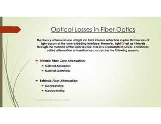
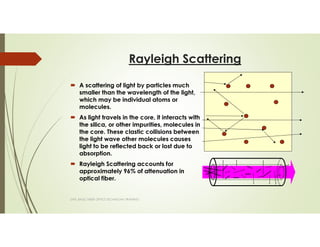
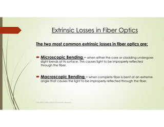
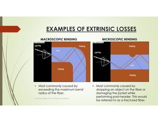
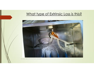
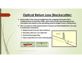
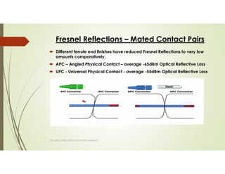
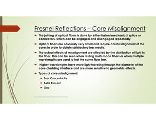
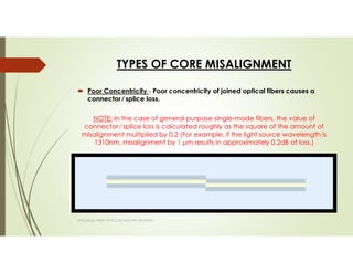
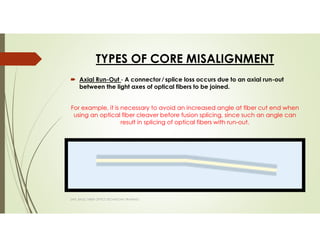
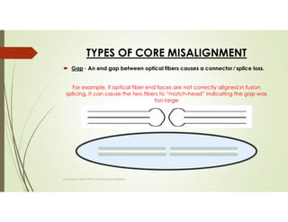
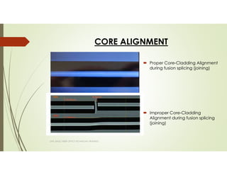
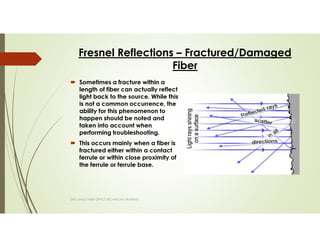
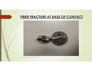
FIBER OPTICS
THEORY AND
APPLICATION
Instructor: Colby Graves
Advantages of Fiber Optics in the Subsea
Oil & Gas Industry
Able to operate in temperature range of -60°C to
+85°C.
Tensile strength of around 100 kpsi for the entire fiber
length
Roughly half the cost of copper wire and
exponentially lighter.
Can easily span over 40 km without amplification
even while subsea.
Non-conductive and completely immune to electro-
magnetic interference.
SAPL BASIC FIBER OPTICS TECHNICIAN TRAINING
Precautions for Fiber Optics
Due to the increased fragility of fiber optics, increased
care must be observed.
The majority of damage caused to fiber optics and fiber
optic connectors is due to external factors otherwise
known as extrinsic absorption.
Technicians should be properly educated on the theory
of fiber optics, as well as, handling and operations, prior
to use.
SAPL BASIC FIBER OPTICS TECHNICIAN TRAINING
Light propagates through optical fibers by the principle of total internal reflection.
Total internal reflection occurs when a core with a higher index of refraction is
encapsulated by a cladding of a lower refractive index.
The velocity at which light travels through in a material is determined by the
refractive index of that material. The refractive index (n) represents the ratio of the
velocity of light in a vacuum to the velocity of light in a material.
Fiber Theory
SAPL BASIC FIBER OPTICS TECHNICIAN TRAINING
The IOR lies typically between 1.4 and 1.5.
The exact value is supplied by the cable manufacturer.
• 1.4677 @1310nm 1.4682 @1550nm
• Water @ 1.33 Diamond @ 2.4
c
v
_
n= Speed of light in the material
Speed of light in a vacuum (299,792,458 meters/sec)
Types of Fiber Optics Used
The HydraLight family of connectors come standard with
either;
Corning SMF-28e+ (Single Mode)
ADC Inc. 900µm HYTREL® tight buffered fiber (Multi
Mode)
SAPL BASIC FIBER OPTICS TECHNICIAN TRAINING
Light Transmission Through Fiber
Single Mode
Multi Mode
SAPL BASIC FIBER OPTICS TECHNICIAN TRAINING
• The radius and index of refraction of the core determines the
number of modes allowed to propagate.
• The larger the core size, the more modes the fiber can transmit.
SAPL BASIC FIBER OPTICS TECHNICIAN TRAINING
Multi-mode
• Lower Cost
• Very small core
• Lower Attenuation
• Higher Bandwidth
• Inexpensive Cable
• Expensive Splicing
• Longer Distance
• High Capacity
• Higher Cost
• Very Large Core
• Higher Attenuation
• Lower Bandwidth
• Expensive Cable
• Inexpensive Splicing
• Shorter Distance
• Lower Capacity
Single Mode
9.0µm 50µm125µm
Corning SMF-28e+ Data Sheet
(Single Mode)
Core Diameter – 8.2 µm
Cladding Diameter – 125.0 ± 0.7µm
1st Coating Diameter - 242 ± 12 µm (Acrylate Coating)
2nd Coating Diameter - 900 µm (Hytrel® Jacket)
SAPL BASIC FIBER OPTICS TECHNICIAN TRAINING
ADC Inc. 900µm HYTREL® tight buffered fiber
Data Sheet
(Multi Mode)
SAPL BASIC FIBER OPTICS TECHNICIAN TRAINING
Core Diameter – 50µm
Cladding Diameter – 125.0µm
1st Coating Diameter - 500µm (Acrylate Coating)
2nd Coating Diameter - 900µm (Hytrel® Jacket)
Transmission Sources for Fiber Testing
Fabry-Perot (FP) and Distributed Feedback (DFB) Lasers
•Used for single mode: 1310 nm, 1550 nm, and 1625nm
•Narrow spectrum (can be less than 1 nm)
•Narrow beam width (does not fill multimode fibers)
•Highest power and fastest switching
•Most expensive (especially DFB)
Light Emitting Diodes (LED)
•Used for multimode: 850 nm or 1300 nm
•Wide beam width fills multimode fibers
•Wider spectrum (typically 50 nm)
•Inexpensive
•Cannot modulate as fast as lasers
SAPL BASIC FIBER OPTICS TECHNICIAN TRAINING
Wavelength
Wavelength
Why do we use certain wavelengths?
SAPL BASIC FIBER OPTICS TECHNICIAN TRAINING
800 900 1000 1100 1200 1300 1400 1500 1600
1st
Window
C -Band 1530 -1560
L -Band 1565 -1610
Wavelength (nm)
0.1
0.7
1.3
1.9
2.5
Reference Point: Visible Light is between 450 and 650 nm
Theoretical Minimum
Attenuation of Single Mode
Fiber
E Band
Optical Loss measurement units - The difference
between dB and dBm.
Loss dB Power Remaining %
0 100
0.2 95.5
0.4 91.2
0.6 87.7
0.8 83.2
1 79.4
2 63.1
3 50.1
4 39.8
5 31.6
6 25.1
7 19.9
8 15.8
9 12.6
10 10
20 1
30 0.1
40 0.01
50 0.001
SAPL BASIC FIBER OPTICS TECHNICIAN TRAINING
• We use the dBm unit when we talk
about POWER which is an absolute
value measured at a specific point
in a link
• Example: The light reflected back to
the laser source can be measured
as an absolute value.
(i.e. -55dBm = 100 nanowatts).
• We use the dB unit when we talk
about a LOSS which is a referenced
value.
• Example: Insertion Loss and
attenuation are measure in dB
because it is actually a ratio
between your beginning and
ending power level.
Optical Losses in Fiber Optics
The theory of transmission of light via total internal reflection implies that no loss of
light occurs at the core-cladding interface. However, light IS lost as it travels
through the material of the optical core. This loss is transmitted power, commonly
called attenuation or insertion loss, occurs for the following reasons:
Intrinsic Fiber Core Attenuation:
Material Absorption
Material Scattering
Extrinsic Fiber Attenuation:
Microbending
Macrobending
SAPL BASIC FIBER OPTICS TECHNICIAN TRAINING
Intrinsic Loss in Fiber Optics
An intrinsic condition is caused by basic fiber-material properties. If an
optical fiber were absolutely pure, with no imperfections or impurities, then
all assimilations would be intrinsic.
In fiber optics, silica (pure glass) fibers are used predominately. Silica fibers
are used because of their low intrinsic material assimilation at the
wavelengths of operation.
Intrinsic loss is unavoidable due to the chemical makeup of the fiber core-
cladding makeup and the science of a powered light source traveling
through a medium.
SAPL BASIC FIBER OPTICS TECHNICIAN TRAINING
Intrinsic Loss in Fiber Optics (Cont.)
Material Absorption – is a loss mechanism which results in the dissipation
of some of the transmitted optical power into heat in the optical fiber.
The main cause of this intrinsic condition in the infrared region is the
characteristic vibration frequency of atomic bonds. In silica glass, this is
caused by the vibration of silicon-oxygen (Si-O) bonds. The interaction
between the vibrating bond and the electromagnetic field of the optical
signal causes the intrinsic condition.
Material Scattering - is the elastic scattering of light by particles much
smaller than the wavelength of the light traveling through the fiber. This
loss mechanism is also referred to Rayleigh Scattering.
The cause of this loss is due to the embedded hydroxyl ions that reflect light
either in a erratic manner allowing it to escape through the fiber or reflect
back to the laser source.
Note: Material Scattering is sometimes referred to as an extrinsic loss due to the intentional
introduction of the hydroxyl ions into the fiber through the manufacture process.
SAPL BASIC FIBER OPTICS TECHNICIAN TRAINING
Rayleigh Scattering
SAPL BASIC FIBER OPTICS TECHNICIAN TRAINING
A scattering of light by particles much
smaller than the wavelength of the light,
which may be individual atoms or
molecules.
As light travels in the core, it interacts with
the silica, or other impurities, molecules in
the core. These clastic collisions between
the light wave other molecules causes
light to be reflected back or lost due to
absorption.
Rayleigh Scattering accounts for
approximately 96% of attenuation in
optical fiber.
Extrinsic Losses in Fiber Optics
The two most common extrinsic losses in fiber optics are;
Microscopic Bending – when either the core or cladding undergoes
slight bends at its surface. This causes light to be improperly reflected
through the fiber.
Macroscopic Bending – when complete fiber is bent at an extreme
angle that causes the light to be improperly reflected through the fiber.
SAPL BASIC FIBER OPTICS TECHNICIAN TRAINING
EXAMPLES OF EXTRINSIC LOSSES
SAPL BASIC FIBER OPTICS TECHNICIAN TRAINING
MACROSCOPIC BENDING MICROSCOPIC BENDING
• Most commonly caused by
exceeding the maximum bend
radius of the fiber.
• Most commonly caused by
dropping an object on the fiber or
damaging the jacket while
performing post-header. This would
be referred to as a fractured fiber.
SAPL BASIC FIBER OPTICS TECHNICIAN TRAINING
What type of Extrinsic Loss is this?
How to avoid Extrinsic Losses
SAPL BASIC FIBER OPTICS TECHNICIAN TRAINING
Do not bend fibers past their maximum bend radius of 25mm.
Do not over-tighten “bundled” fibers with cable-ties of any other securing
device.
Do not pull on the fiber optics, especially at the connector. (Optical
penetrators are only rated at 4-5 lbs. of linear force.)
Take precautions to not drop tooling or equipment on fiber.
Be mindful of the fiber you are working with and the technician next to you.
While extrinsic loss may not always be visible to the naked eye, if you think
you may have damaged it, notify a supervisor immediately for further
investigation.
Optical Return Loss (Backscatter)
Backscatter is the amount of light from the outgoing test pulse that is
scattered back toward the OTDR, which looks at the returning signal and
calculates loss based on the declining amount of light it sees coming back.
The occurrence of the phenomenon is known as Fresnel Reflection Loss and
is commonly caused by:
Mated Contact Pairs (Air Glass Interface)
Bad splice with poor core alignment
Fractured/Damaged Fiber
Open-ended fiber (no index matching gel)
SAPL BASIC FIBER OPTICS TECHNICIAN TRAINING
Loss
Reflection
Fresnel Reflections – Mated Contact Pairs
Different ferrule end finishes have reduced Fresnel Reflections to very low
amounts comparatively.
APC – Angled Physical Contact – average -65dBm Optical Reflective Loss
UPC - Universal Physical Contact - average -55dBm Optical Reflective Loss
SAPL BASIC FIBER OPTICS TECHNICIAN TRAINING
Fresnel Reflections – Core Misalignment
SAPL BASIC FIBER OPTICS TECHNICIAN TRAINING
The joining of optical fibers is done by either fusion/mechanical splice or
connectors, which can be engaged and disengaged repeatedly.
Optical fibers are obviously very small and require careful alignment of the
cores in order to obtain satisfactory loss results.
The actual effects of misalignment are affected by the distribution of light in
the fiber. This can be seen when testing multi-mode fibers or when multiple
wavelengths are used to test the same fiber line.
Higher wavelengths have more light traveling through the diameter of the
core-cladding interface and are more sensitive to geometric effects.
Types of core misalignment:
Poor Concentricity
Axial Run-out
Gap
TYPES OF CORE MISALIGNMENT
Poor Concentricity - Poor concentricity of joined optical fibers causes a
connector ⁄ splice loss.
NOTE: In the case of general purpose single-mode fibers, the value of
connector ⁄ splice loss is calculated roughly as the square of the amount of
misalignment multiplied by 0.2 (For example, if the light source wavelength is
1310nm, misalignment by 1 µm results in approximately 0.2dB of loss.)
SAPL BASIC FIBER OPTICS TECHNICIAN TRAINING
TYPES OF CORE MISALIGNMENT
Axial Run-Out - A connector ⁄ splice loss occurs due to an axial run-out
between the light axes of optical fibers to be joined.
For example, it is necessary to avoid an increased angle at fiber cut end when
using an optical fiber cleaver before fusion splicing, since such an angle can
result in splicing of optical fibers with run-out.
SAPL BASIC FIBER OPTICS TECHNICIAN TRAINING
TYPES OF CORE MISALIGNMENT
Gap - An end gap between optical fibers causes a connector ⁄ splice loss.
For example, if optical fiber end faces are not correctly aligned in fusion
splicing, it can cause the two fibers to “match-head” indicating the gap was
too large
SAPL BASIC FIBER OPTICS TECHNICIAN TRAINING
CORE ALIGNMENT
SAPL BASIC FIBER OPTICS TECHNICIAN TRAINING
Proper Core-Cladding Alignment
during fusion splicing (joining)
Improper Core-Cladding
Alignment during fusion splicing
(joining)
Fresnel Reflections – Fractured/Damaged
Fiber
SAPL BASIC FIBER OPTICS TECHNICIAN TRAINING
Sometimes a fracture within a
length of fiber can actually reflect
light back to the source. While this
is not a common occurrence, the
ability for this phenomenon to
happen should be noted and
taken into account when
performing troubleshooting.
This occurs mainly when a fiber is
fractured either within a contact
ferrule or within close proximity of
the ferrule or ferrule base.
FIBER FRACTURE AT BASE OF CONTACT
SAPL BASIC FIBER OPTICS TECHNICIAN TRAINING
Fresnel Reflections – Open-Ended Fiber
without Index Matching Gel
SAPL BASIC FIBER OPTICS TECHNICIAN TRAINING
If you are testing short cables with
highly reflective connectors or a
cable with an open or
inaccessible end, you will likely
encounter “ghosts.” These are
caused by the reflected light from
the far end connector reflecting
back and forth in the fiber until it is
attenuated to the noise level.
If you have access to the opposite
end, place index matching gel on
the fiber in order to deaden the
light and “clean up” the optical
trace.
Summary
The theory of photonics is just that, a theory. The fiber
optics field is ever-evolving to encompass faster
transmission rates, longer continuous spans without
amplification, and increased durability with lower costs.
The information expressed in this presentation is to inform
you of the basic principles of fiber optic theory and
application for their daily duties. Now that you have seen
the basic functionality of fiber optics, it is up to YOU to
continue to attain the vast amount of knowledge that is
available on countless public forums, literature,
publications and the internet.
SAPL BASIC FIBER OPTICS TECHNICIAN TRAINING
Q & A
Was this block of instruction educational?
Did you understand the subject matter discussed?
What is a topic for future training that you would like to
see discussed?
Where should future efforts be focused in order to
improve the overall education of the Fiber Optics
Technicians?
SAPL BASIC FIBER OPTICS TECHNICIAN TRAINING

Fiber optics theory training

  • 1.
  • 2.
    Advantages of FiberOptics in the Subsea Oil & Gas Industry Able to operate in temperature range of -60°C to +85°C. Tensile strength of around 100 kpsi for the entire fiber length Roughly half the cost of copper wire and exponentially lighter. Can easily span over 40 km without amplification even while subsea. Non-conductive and completely immune to electro- magnetic interference. SAPL BASIC FIBER OPTICS TECHNICIAN TRAINING
  • 3.
    Precautions for FiberOptics Due to the increased fragility of fiber optics, increased care must be observed. The majority of damage caused to fiber optics and fiber optic connectors is due to external factors otherwise known as extrinsic absorption. Technicians should be properly educated on the theory of fiber optics, as well as, handling and operations, prior to use. SAPL BASIC FIBER OPTICS TECHNICIAN TRAINING
  • 4.
    Light propagates throughoptical fibers by the principle of total internal reflection. Total internal reflection occurs when a core with a higher index of refraction is encapsulated by a cladding of a lower refractive index. The velocity at which light travels through in a material is determined by the refractive index of that material. The refractive index (n) represents the ratio of the velocity of light in a vacuum to the velocity of light in a material. Fiber Theory SAPL BASIC FIBER OPTICS TECHNICIAN TRAINING The IOR lies typically between 1.4 and 1.5. The exact value is supplied by the cable manufacturer. • 1.4677 @1310nm 1.4682 @1550nm • Water @ 1.33 Diamond @ 2.4 c v _ n= Speed of light in the material Speed of light in a vacuum (299,792,458 meters/sec)
  • 5.
    Types of FiberOptics Used The HydraLight family of connectors come standard with either; Corning SMF-28e+ (Single Mode) ADC Inc. 900µm HYTREL® tight buffered fiber (Multi Mode) SAPL BASIC FIBER OPTICS TECHNICIAN TRAINING
  • 6.
    Light Transmission ThroughFiber Single Mode Multi Mode SAPL BASIC FIBER OPTICS TECHNICIAN TRAINING • The radius and index of refraction of the core determines the number of modes allowed to propagate. • The larger the core size, the more modes the fiber can transmit.
  • 7.
    SAPL BASIC FIBEROPTICS TECHNICIAN TRAINING Multi-mode • Lower Cost • Very small core • Lower Attenuation • Higher Bandwidth • Inexpensive Cable • Expensive Splicing • Longer Distance • High Capacity • Higher Cost • Very Large Core • Higher Attenuation • Lower Bandwidth • Expensive Cable • Inexpensive Splicing • Shorter Distance • Lower Capacity Single Mode 9.0µm 50µm125µm
  • 8.
    Corning SMF-28e+ DataSheet (Single Mode) Core Diameter – 8.2 µm Cladding Diameter – 125.0 ± 0.7µm 1st Coating Diameter - 242 ± 12 µm (Acrylate Coating) 2nd Coating Diameter - 900 µm (Hytrel® Jacket) SAPL BASIC FIBER OPTICS TECHNICIAN TRAINING
  • 9.
    ADC Inc. 900µmHYTREL® tight buffered fiber Data Sheet (Multi Mode) SAPL BASIC FIBER OPTICS TECHNICIAN TRAINING Core Diameter – 50µm Cladding Diameter – 125.0µm 1st Coating Diameter - 500µm (Acrylate Coating) 2nd Coating Diameter - 900µm (Hytrel® Jacket)
  • 10.
    Transmission Sources forFiber Testing Fabry-Perot (FP) and Distributed Feedback (DFB) Lasers •Used for single mode: 1310 nm, 1550 nm, and 1625nm •Narrow spectrum (can be less than 1 nm) •Narrow beam width (does not fill multimode fibers) •Highest power and fastest switching •Most expensive (especially DFB) Light Emitting Diodes (LED) •Used for multimode: 850 nm or 1300 nm •Wide beam width fills multimode fibers •Wider spectrum (typically 50 nm) •Inexpensive •Cannot modulate as fast as lasers SAPL BASIC FIBER OPTICS TECHNICIAN TRAINING Wavelength Wavelength
  • 11.
    Why do weuse certain wavelengths? SAPL BASIC FIBER OPTICS TECHNICIAN TRAINING 800 900 1000 1100 1200 1300 1400 1500 1600 1st Window C -Band 1530 -1560 L -Band 1565 -1610 Wavelength (nm) 0.1 0.7 1.3 1.9 2.5 Reference Point: Visible Light is between 450 and 650 nm Theoretical Minimum Attenuation of Single Mode Fiber E Band
  • 12.
    Optical Loss measurementunits - The difference between dB and dBm. Loss dB Power Remaining % 0 100 0.2 95.5 0.4 91.2 0.6 87.7 0.8 83.2 1 79.4 2 63.1 3 50.1 4 39.8 5 31.6 6 25.1 7 19.9 8 15.8 9 12.6 10 10 20 1 30 0.1 40 0.01 50 0.001 SAPL BASIC FIBER OPTICS TECHNICIAN TRAINING • We use the dBm unit when we talk about POWER which is an absolute value measured at a specific point in a link • Example: The light reflected back to the laser source can be measured as an absolute value. (i.e. -55dBm = 100 nanowatts). • We use the dB unit when we talk about a LOSS which is a referenced value. • Example: Insertion Loss and attenuation are measure in dB because it is actually a ratio between your beginning and ending power level.
  • 13.
    Optical Losses inFiber Optics The theory of transmission of light via total internal reflection implies that no loss of light occurs at the core-cladding interface. However, light IS lost as it travels through the material of the optical core. This loss is transmitted power, commonly called attenuation or insertion loss, occurs for the following reasons: Intrinsic Fiber Core Attenuation: Material Absorption Material Scattering Extrinsic Fiber Attenuation: Microbending Macrobending SAPL BASIC FIBER OPTICS TECHNICIAN TRAINING
  • 14.
    Intrinsic Loss inFiber Optics An intrinsic condition is caused by basic fiber-material properties. If an optical fiber were absolutely pure, with no imperfections or impurities, then all assimilations would be intrinsic. In fiber optics, silica (pure glass) fibers are used predominately. Silica fibers are used because of their low intrinsic material assimilation at the wavelengths of operation. Intrinsic loss is unavoidable due to the chemical makeup of the fiber core- cladding makeup and the science of a powered light source traveling through a medium. SAPL BASIC FIBER OPTICS TECHNICIAN TRAINING
  • 15.
    Intrinsic Loss inFiber Optics (Cont.) Material Absorption – is a loss mechanism which results in the dissipation of some of the transmitted optical power into heat in the optical fiber. The main cause of this intrinsic condition in the infrared region is the characteristic vibration frequency of atomic bonds. In silica glass, this is caused by the vibration of silicon-oxygen (Si-O) bonds. The interaction between the vibrating bond and the electromagnetic field of the optical signal causes the intrinsic condition. Material Scattering - is the elastic scattering of light by particles much smaller than the wavelength of the light traveling through the fiber. This loss mechanism is also referred to Rayleigh Scattering. The cause of this loss is due to the embedded hydroxyl ions that reflect light either in a erratic manner allowing it to escape through the fiber or reflect back to the laser source. Note: Material Scattering is sometimes referred to as an extrinsic loss due to the intentional introduction of the hydroxyl ions into the fiber through the manufacture process. SAPL BASIC FIBER OPTICS TECHNICIAN TRAINING
  • 16.
    Rayleigh Scattering SAPL BASICFIBER OPTICS TECHNICIAN TRAINING A scattering of light by particles much smaller than the wavelength of the light, which may be individual atoms or molecules. As light travels in the core, it interacts with the silica, or other impurities, molecules in the core. These clastic collisions between the light wave other molecules causes light to be reflected back or lost due to absorption. Rayleigh Scattering accounts for approximately 96% of attenuation in optical fiber.
  • 17.
    Extrinsic Losses inFiber Optics The two most common extrinsic losses in fiber optics are; Microscopic Bending – when either the core or cladding undergoes slight bends at its surface. This causes light to be improperly reflected through the fiber. Macroscopic Bending – when complete fiber is bent at an extreme angle that causes the light to be improperly reflected through the fiber. SAPL BASIC FIBER OPTICS TECHNICIAN TRAINING
  • 18.
    EXAMPLES OF EXTRINSICLOSSES SAPL BASIC FIBER OPTICS TECHNICIAN TRAINING MACROSCOPIC BENDING MICROSCOPIC BENDING • Most commonly caused by exceeding the maximum bend radius of the fiber. • Most commonly caused by dropping an object on the fiber or damaging the jacket while performing post-header. This would be referred to as a fractured fiber.
  • 19.
    SAPL BASIC FIBEROPTICS TECHNICIAN TRAINING What type of Extrinsic Loss is this?
  • 20.
    How to avoidExtrinsic Losses SAPL BASIC FIBER OPTICS TECHNICIAN TRAINING Do not bend fibers past their maximum bend radius of 25mm. Do not over-tighten “bundled” fibers with cable-ties of any other securing device. Do not pull on the fiber optics, especially at the connector. (Optical penetrators are only rated at 4-5 lbs. of linear force.) Take precautions to not drop tooling or equipment on fiber. Be mindful of the fiber you are working with and the technician next to you. While extrinsic loss may not always be visible to the naked eye, if you think you may have damaged it, notify a supervisor immediately for further investigation.
  • 21.
    Optical Return Loss(Backscatter) Backscatter is the amount of light from the outgoing test pulse that is scattered back toward the OTDR, which looks at the returning signal and calculates loss based on the declining amount of light it sees coming back. The occurrence of the phenomenon is known as Fresnel Reflection Loss and is commonly caused by: Mated Contact Pairs (Air Glass Interface) Bad splice with poor core alignment Fractured/Damaged Fiber Open-ended fiber (no index matching gel) SAPL BASIC FIBER OPTICS TECHNICIAN TRAINING Loss Reflection
  • 22.
    Fresnel Reflections –Mated Contact Pairs Different ferrule end finishes have reduced Fresnel Reflections to very low amounts comparatively. APC – Angled Physical Contact – average -65dBm Optical Reflective Loss UPC - Universal Physical Contact - average -55dBm Optical Reflective Loss SAPL BASIC FIBER OPTICS TECHNICIAN TRAINING
  • 23.
    Fresnel Reflections –Core Misalignment SAPL BASIC FIBER OPTICS TECHNICIAN TRAINING The joining of optical fibers is done by either fusion/mechanical splice or connectors, which can be engaged and disengaged repeatedly. Optical fibers are obviously very small and require careful alignment of the cores in order to obtain satisfactory loss results. The actual effects of misalignment are affected by the distribution of light in the fiber. This can be seen when testing multi-mode fibers or when multiple wavelengths are used to test the same fiber line. Higher wavelengths have more light traveling through the diameter of the core-cladding interface and are more sensitive to geometric effects. Types of core misalignment: Poor Concentricity Axial Run-out Gap
  • 24.
    TYPES OF COREMISALIGNMENT Poor Concentricity - Poor concentricity of joined optical fibers causes a connector ⁄ splice loss. NOTE: In the case of general purpose single-mode fibers, the value of connector ⁄ splice loss is calculated roughly as the square of the amount of misalignment multiplied by 0.2 (For example, if the light source wavelength is 1310nm, misalignment by 1 µm results in approximately 0.2dB of loss.) SAPL BASIC FIBER OPTICS TECHNICIAN TRAINING
  • 25.
    TYPES OF COREMISALIGNMENT Axial Run-Out - A connector ⁄ splice loss occurs due to an axial run-out between the light axes of optical fibers to be joined. For example, it is necessary to avoid an increased angle at fiber cut end when using an optical fiber cleaver before fusion splicing, since such an angle can result in splicing of optical fibers with run-out. SAPL BASIC FIBER OPTICS TECHNICIAN TRAINING
  • 26.
    TYPES OF COREMISALIGNMENT Gap - An end gap between optical fibers causes a connector ⁄ splice loss. For example, if optical fiber end faces are not correctly aligned in fusion splicing, it can cause the two fibers to “match-head” indicating the gap was too large SAPL BASIC FIBER OPTICS TECHNICIAN TRAINING
  • 27.
    CORE ALIGNMENT SAPL BASICFIBER OPTICS TECHNICIAN TRAINING Proper Core-Cladding Alignment during fusion splicing (joining) Improper Core-Cladding Alignment during fusion splicing (joining)
  • 28.
    Fresnel Reflections –Fractured/Damaged Fiber SAPL BASIC FIBER OPTICS TECHNICIAN TRAINING Sometimes a fracture within a length of fiber can actually reflect light back to the source. While this is not a common occurrence, the ability for this phenomenon to happen should be noted and taken into account when performing troubleshooting. This occurs mainly when a fiber is fractured either within a contact ferrule or within close proximity of the ferrule or ferrule base.
  • 29.
    FIBER FRACTURE ATBASE OF CONTACT SAPL BASIC FIBER OPTICS TECHNICIAN TRAINING
  • 30.
    Fresnel Reflections –Open-Ended Fiber without Index Matching Gel SAPL BASIC FIBER OPTICS TECHNICIAN TRAINING If you are testing short cables with highly reflective connectors or a cable with an open or inaccessible end, you will likely encounter “ghosts.” These are caused by the reflected light from the far end connector reflecting back and forth in the fiber until it is attenuated to the noise level. If you have access to the opposite end, place index matching gel on the fiber in order to deaden the light and “clean up” the optical trace.
  • 31.
    Summary The theory ofphotonics is just that, a theory. The fiber optics field is ever-evolving to encompass faster transmission rates, longer continuous spans without amplification, and increased durability with lower costs. The information expressed in this presentation is to inform you of the basic principles of fiber optic theory and application for their daily duties. Now that you have seen the basic functionality of fiber optics, it is up to YOU to continue to attain the vast amount of knowledge that is available on countless public forums, literature, publications and the internet. SAPL BASIC FIBER OPTICS TECHNICIAN TRAINING
  • 32.
    Q & A Wasthis block of instruction educational? Did you understand the subject matter discussed? What is a topic for future training that you would like to see discussed? Where should future efforts be focused in order to improve the overall education of the Fiber Optics Technicians? SAPL BASIC FIBER OPTICS TECHNICIAN TRAINING