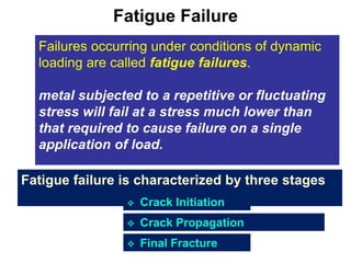
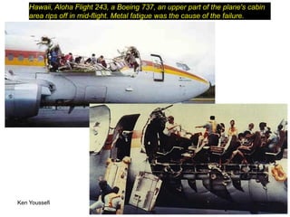
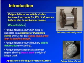
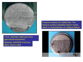
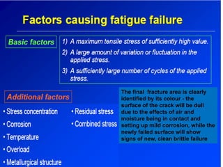
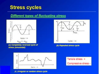
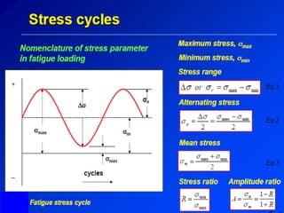
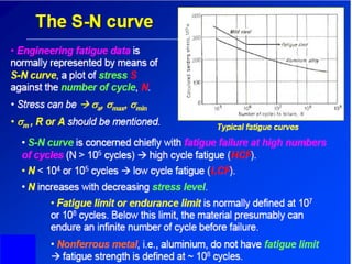
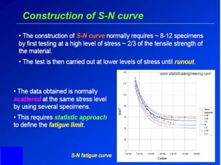
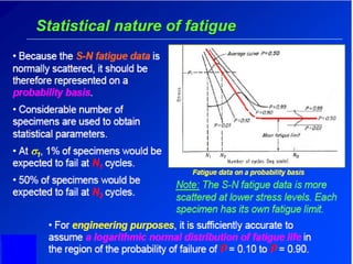
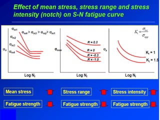
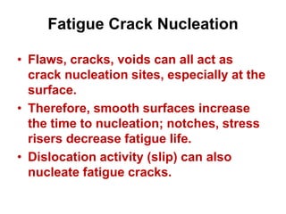
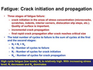
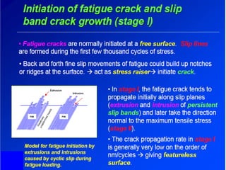
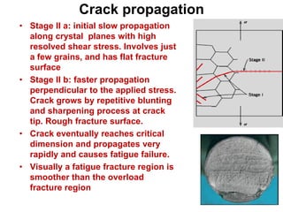
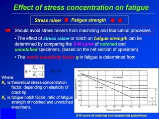
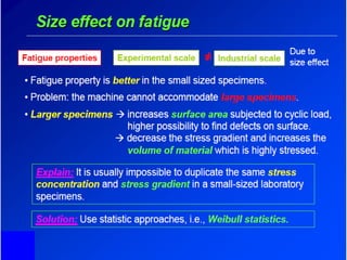
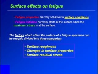
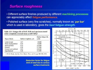
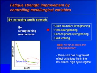
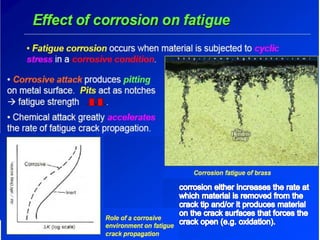
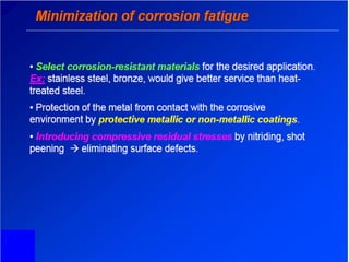
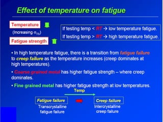
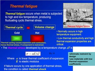
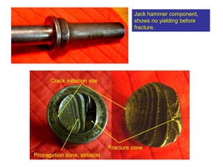
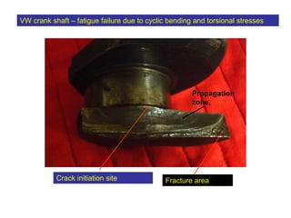
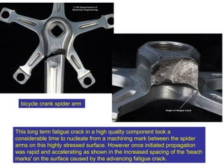
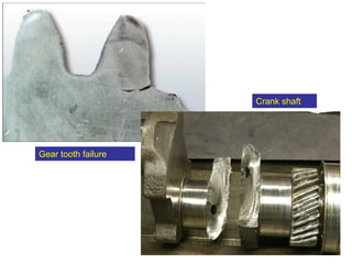
BMFB 4283
NDT & FAILURE ANALYSIS
Lectures for Week 10
Prof. Qumrul Ahsan, PhD
Department of Engineering Materials
Faculty of Manufacturing Engineering
10.0 Fatigue Failure
10.1 Introduction
10.2 Factors Causing Fatigue Failure
10.3 S-N Curve
10.4 Fatigue Crack Growth
10.5 Factors Influence Fatigue Properties
Issues to address
Failures occurring under conditions of dynamic
loading are called fatigue failures.
metal subjected to a repetitive or fluctuating
stress will fail at a stress much lower than
that required to cause failure on a single
application of load.
Fatigue Failure
Fatigue failure is characterized by three stages
 Crack Initiation
 Crack Propagation
 Final Fracture
Ken Youssefi MAE dept., SJSU 4
Hawaii, Aloha Flight 243, a Boeing 737, an upper part of the plane's cabin
area rips off in mid-flight. Metal fatigue was the cause of the failure.
Appearance of Fatigue Fracture Surface
1.0-in. diameter steel pins from
agricultural equipment.
Material; AISI/SAE 4140 low
allow carbon steel
Fracture surface of a failed bolt. The
fracture surface exhibited beach marks,
which is characteristic of a fatigue failure.
The final fracture area is clearly
identified by its colour - the
surface of the crack will be dull
due to the effects of air and
moisture being in contact and
setting up mild corrosion, while the
newly failed surface will show
signs of new, clean brittle failure
Fatigue Crack Nucleation
• Flaws, cracks, voids can all act as
crack nucleation sites, especially at the
surface.
• Therefore, smooth surfaces increase
the time to nucleation; notches, stress
risers decrease fatigue life.
• Dislocation activity (slip) can also
nucleate fatigue cracks.
Fatigue: Crack initiation and propagation
• Three stages of fatigue failure:
– crack initiation in the areas of stress concentration (microcracks,
scratches, indents, interior corners, dislocation slip steps, etc.).
Quality of surface is important.
– incremental crack propagation
– final rapid crack propagation after crack reaches critical size
• The total number of cycles to failure is the sum of cycles at the first
and the second stages:
– Nf = Ni + Np
– Nf : Number of cycles to failure
– Ni : Number of cycles for crack initiation
– Np : Number of cycles for crack propagation
High cycle fatigue (low loads): Ni is relatively high. With increasing stress
level, Ni decreases and Np dominates
Crack propagation
• Stage II a: initial slow propagation
along crystal planes with high
resolved shear stress. Involves just
a few grains, and has flat fracture
surface
• Stage II b: faster propagation
perpendicular to the applied stress.
Crack grows by repetitive blunting
and sharpening process at crack
tip. Rough fracture surface.
• Crack eventually reaches critical
dimension and propagates very
rapidly and causes fatigue failure.
• Visually a fatigue fracture region is
smoother than the overload
fracture region
Indication of Fatigue Failure Surface
Crack initiation site
Fracture zone
Beach Mark
Both marks indicate the
position of the crack tip. It
appears as concentric ridges
(circular or semicircular
Beach Mark
•Also called calmshell marks
•Can be observed using unaided eye
•Components experienced interruption
during the crack propagation
•Each beachmark band represents a
time over which crack growth occured
Striations
• Microscopic in size
•Each striation represents crack
growth rate
• stress range  striations width
• Multiple strations within a beach
mark
25
928 Porsche timing pulley
Crack started at the fillet
Fatigue at Stress Raiser
• Notches decrease fatigue life
through stress concentration
• Remove stress concentrators.
bad
bad
better
better
Thermal cycling causes expansion and contraction,
hence thermal stress, if component is restrained.
•eliminate restraint by
design
•use materials with low
thermal expansion
coefficients
MAE dept., SJSU
Jack hammer component,
shows no yielding before
fracture.
Crack initiation site
Fracture zone
Propagation zone, striation
VW crank shaft – fatigue failure due to cyclic bending and torsional stresses
Fracture area
Crack initiation site
Propagation
zone,
This long term fatigue crack in a high quality component took a
considerable time to nucleate from a machining mark between the spider
arms on this highly stressed surface. However once initiated propagation
was rapid and accelerating as shown in the increased spacing of the 'beach
marks' on the surface caused by the advancing fatigue crack.
bicycle crank spider arm
MAE dept., SJSU 42
Gear tooth failure
Crank shaft
43
Fatigue: summary
• Initiated at surface
• Fatigue failure controlled either by initiation or by
propagation
• Fatigue Fracture Features: Beachmark and
Striation
• Intrinsic and Extrinsic features control fatigue
failure and fatigue life.

fatigue-failures_compress.pdf

  • 1.
    BMFB 4283 NDT &FAILURE ANALYSIS Lectures for Week 10 Prof. Qumrul Ahsan, PhD Department of Engineering Materials Faculty of Manufacturing Engineering
  • 2.
    10.0 Fatigue Failure 10.1Introduction 10.2 Factors Causing Fatigue Failure 10.3 S-N Curve 10.4 Fatigue Crack Growth 10.5 Factors Influence Fatigue Properties Issues to address
  • 3.
    Failures occurring underconditions of dynamic loading are called fatigue failures. metal subjected to a repetitive or fluctuating stress will fail at a stress much lower than that required to cause failure on a single application of load. Fatigue Failure Fatigue failure is characterized by three stages  Crack Initiation  Crack Propagation  Final Fracture
  • 4.
    Ken Youssefi MAEdept., SJSU 4 Hawaii, Aloha Flight 243, a Boeing 737, an upper part of the plane's cabin area rips off in mid-flight. Metal fatigue was the cause of the failure.
  • 5.
    Appearance of FatigueFracture Surface
  • 6.
    1.0-in. diameter steelpins from agricultural equipment. Material; AISI/SAE 4140 low allow carbon steel Fracture surface of a failed bolt. The fracture surface exhibited beach marks, which is characteristic of a fatigue failure.
  • 7.
    The final fracturearea is clearly identified by its colour - the surface of the crack will be dull due to the effects of air and moisture being in contact and setting up mild corrosion, while the newly failed surface will show signs of new, clean brittle failure
  • 14.
    Fatigue Crack Nucleation •Flaws, cracks, voids can all act as crack nucleation sites, especially at the surface. • Therefore, smooth surfaces increase the time to nucleation; notches, stress risers decrease fatigue life. • Dislocation activity (slip) can also nucleate fatigue cracks.
  • 15.
    Fatigue: Crack initiationand propagation • Three stages of fatigue failure: – crack initiation in the areas of stress concentration (microcracks, scratches, indents, interior corners, dislocation slip steps, etc.). Quality of surface is important. – incremental crack propagation – final rapid crack propagation after crack reaches critical size • The total number of cycles to failure is the sum of cycles at the first and the second stages: – Nf = Ni + Np – Nf : Number of cycles to failure – Ni : Number of cycles for crack initiation – Np : Number of cycles for crack propagation High cycle fatigue (low loads): Ni is relatively high. With increasing stress level, Ni decreases and Np dominates
  • 17.
    Crack propagation • StageII a: initial slow propagation along crystal planes with high resolved shear stress. Involves just a few grains, and has flat fracture surface • Stage II b: faster propagation perpendicular to the applied stress. Crack grows by repetitive blunting and sharpening process at crack tip. Rough fracture surface. • Crack eventually reaches critical dimension and propagates very rapidly and causes fatigue failure. • Visually a fatigue fracture region is smoother than the overload fracture region
  • 19.
    Indication of FatigueFailure Surface Crack initiation site Fracture zone Beach Mark Both marks indicate the position of the crack tip. It appears as concentric ridges (circular or semicircular Beach Mark •Also called calmshell marks •Can be observed using unaided eye •Components experienced interruption during the crack propagation •Each beachmark band represents a time over which crack growth occured Striations • Microscopic in size •Each striation represents crack growth rate • stress range  striations width • Multiple strations within a beach mark
  • 25.
    25 928 Porsche timingpulley Crack started at the fillet Fatigue at Stress Raiser • Notches decrease fatigue life through stress concentration • Remove stress concentrators. bad bad better better
  • 38.
    Thermal cycling causesexpansion and contraction, hence thermal stress, if component is restrained. •eliminate restraint by design •use materials with low thermal expansion coefficients
  • 39.
    MAE dept., SJSU Jackhammer component, shows no yielding before fracture. Crack initiation site Fracture zone Propagation zone, striation
  • 40.
    VW crank shaft– fatigue failure due to cyclic bending and torsional stresses Fracture area Crack initiation site Propagation zone,
  • 41.
    This long termfatigue crack in a high quality component took a considerable time to nucleate from a machining mark between the spider arms on this highly stressed surface. However once initiated propagation was rapid and accelerating as shown in the increased spacing of the 'beach marks' on the surface caused by the advancing fatigue crack. bicycle crank spider arm
  • 42.
    MAE dept., SJSU42 Gear tooth failure Crank shaft
  • 43.
    43 Fatigue: summary • Initiatedat surface • Fatigue failure controlled either by initiation or by propagation • Fatigue Fracture Features: Beachmark and Striation • Intrinsic and Extrinsic features control fatigue failure and fatigue life.