The document presents a static and normal mode analysis of an aircraft's avionics compartment door, detailing its structural design and safety considerations. Using CAD software and finite element method (FEM), the analysis iteratively tests various stiffener configurations to ensure the door meets safety and displacement requirements. Results indicate that the final design effectively withstands applied loads without risk of resonance, ensuring flight safety and structural integrity.
![International Journal of Engineering Science Invention
ISSN (Online): 2319 – 6734, ISSN (Print): 2319 – 6726
www.ijesi.org Volume 3 Issue 8 ǁ August 2014 ǁ PP.37-43
www.ijesi.org 37 | Page
Static and Normal Mode Analysis of Aircraft Avionics Compartment Door Veerbhadrappa prabhushetty1, Sunil Mangshetty2 1. Post graduate student, Department of Mechanical Engineering, PDA College of Engineering, Gulbarga, Karnataka, India. 2. Associate Professor, Department of Mechanical Engineering, PDA College of Engineering, Gulbarga, Karnataka, India ABSTRACT : The aircraft has the following fuselage doors like Passenger door, Galley service door two overawing emergency exits, Flight compartment overhead escape hatch, Cargo door, Avionics compartment door, aft equipment compartment door. The avionics compartment door is used to gain access to the equipment in the avionics Compartment. It is located on the centerline of the lower forward fuselage. The door opens inward and moves up on four spring--loaded roller arms. The door is an important part of the airplane, and the reliability of opening the door has a great effect on flight safety. The inadvertent opening could lead to terrible consequence during flight. In this present work a conceptual design of aircraft door is done using cad software meshing using FEM and analysis using MSc Nastran. The static and normal mode analysis of aircraft door frame and stiffeners is done using aluminum material. KEYWORDS: Aircraft door, Static Analysis, Normal Analysis, Finite Element Model
I. INTRODUCTION
Passenger door
The passenger door is located at the forward left side of the fuselage and is the main entrance and exit to the cabin area The passenger door incorporates integral stairs with a retractable lower step and folding handrails. The door is hinged at the cabin floor level and opens outward. A counter--balance mechanism with gas springs is used to take the weight of the door and to dampen the door movement at the fully open position, the door rests on a support wheel. Handrails are provided to assist passengers in boarding and disembarking. Mechanical linkages raise the handrails when the door is opened and collapse them when the door is closed. When a jet way is used, the handrails must be collapsed. Collapsing of the handrails is done by removing the forward and aft handrail quick--release pins (Refer to Lowering the Stair Handrails).Closing the passenger door from inside the aircraft is normally accomplished using the power assist system which is controlled from a DOOR ASSIST switch light on the forward flight attendants panel. The passenger door status is displayed on the EICAS primary page in the form of warning and caution messages and on the DOOR synoptic page. The DOOR synoptic page is displayed when selected from the EICAS control panel [1]. A. Static Analysis A static analysis calculates the effects of steady loading conditions on a structure, while ignoring inertia and damping effects, such as those caused by time-varying loads. A static analysis can, however, include steady inertia loads (such as gravity and rotational velocity), and time-varying loads that can be approximated as static equivalent loads (such as the static equivalent wind and seismic loads commonly defined in many building codes).Static analysis is used to determine the displacements, stresses, strains, and forces in structures or components caused by loads that do not induce significant inertia and damping effects.
B. Normal Mode Analysis
We use Normal mode analysis to determine the vibration characteristics (natural frequencies and mode shapes) of a structure or a machine component while it is being designed. It also can be a starting point for another, more detailed, dynamic analysis, such as a transient dynamic analysis, a harmonic response analysis, or a spectrum analysis. The natural frequencies and mode shapes are important parameters in the design of a structure for dynamic loading conditions,](https://image.slidesharecdn.com/f0382037043-140906052743-phpapp02/85/Static-and-Normal-Mode-Analysis-of-Aircraft-Avionics-Compartment-Door-1-320.jpg)


![Static And Normal Mode Analysis…
www.ijesi.org 42 | Page
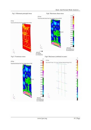
Table1: Conclusion for static analysis
Table 2: Conclusion for normal mode analysis
MODE
FREQUENCY
DISPLACEMENT
1
2.9881
0.655
2
4.05
1.23
3
4.27
1.35
4
4.86
1.16
5
5.04
1.62
V. CONCLUSION From the above static and normal mode analysis we have seen that stress, displacement and frequency are within the limit. In static analysis Z-shape stiffeners are provided for the door skin to provide resistance to the door and import strength to the door for the applied forces and pressure and for the normal mode analysis we have seen that the obtained frequency is in the range of 2-6 Hz less than that of the normal aircraft frequency i.e. 10-15 Hz. So there is no resonance which will not cause heavy vibration and catastrophic failure of the door structure. VI. FUTURE SCOPE OF THE PROJECT In this project the door skin and stiffeners are analyzed using the metallic material .In order to reduce the cost of the door assembly and weight .further the door skin along with stiffeners are made of composite so that there is an overall cost reduction and weight of the door structure.
REFERENCES
[1] Bombardier CRJ-200; WWW2. Bombardie.com
[2] MICHAEL CHUN-YUNG NIU “Airframe structural design” practical design information and data on aircraft structures.
[3] Muniyasamy Kalanchiam and Baskar Mannai “Topology Optimization of Aircraft Fuselage Structure”.
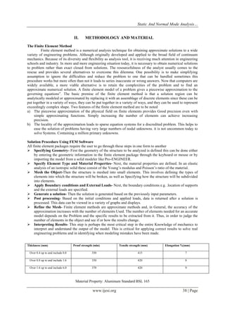
SL.No
Structure component
Material Specification
Type of stress
Developed Stress(Mpa)
Allowable stress(Mpa)
Reserve Factor (RF)
Remarks
1
Door skin with stiffeners
Aluminum Standard: BSL 165
Max Principal Stress
334
415
1.24
RF>1 structure is safe
Minimum principal Stress
367
415
1.13
RF>1 structure is safe
Max shear stress
187
247
1.32
RF>1 structure is safe
Vonmises stress
346
415
1.19
RF>1 structure is safe
Max combined at center
403
415
1.02
RF>1 structure is safe](https://image.slidesharecdn.com/f0382037043-140906052743-phpapp02/85/Static-and-Normal-Mode-Analysis-of-Aircraft-Avionics-Compartment-Door-6-320.jpg)
![Static And Normal Mode Analysis…
www.ijesi.org 43 | Page
[4] KHAIRI YUSUF, NUKMAN Y., S. Z. DAWAL,DEVI CHANDRA, N. SOFIA Conceptual Design of Fuselage Structure of Very Light Jet Aircraft”.
[5] KANG JIANXIONG, GAO HANGSHAN, WANG FUSHENG, AND YUE ZHUFENG “Effect of Detail Design on Fatigue Performance of Aircraft Door Frame” Department of Engineering Mechanics, Northwestern Polytechnical University, Xi'an 710129, China [6] UKADGAONKER, VG; AWASARE, PJ; GADE, SV “Stress analysis of door and window of a passenger aircraft”
[7] Z K Awad1, F Gonzalez2 and T Aravinthan “Advanced robust design optimization of FRP sandwich floor panels”. 1 Centre of Excellence in Engineering Fibre Composite (CEEFC), University of Southern Queensland (USQ), Toowoomba QLD 4350, AU 2 Faculty of Built Environment & Engineering, Queensland University of Technology (QUT), Brisbane, AU [8] SHAH, K., KANG, H., AND DESHMUKH, U., "Design of Dual Sliding Door for a Small-size Car and Its Validation Using CAE Tools," SAE Technical Paper 2007-01-0889, 2007, doi:10.4271/2007-01-0889. [9] DARYL GRUAR “AUTOMATION PROCESS OF „KING AIR‟ AIRCRAFT - CARGO DOOR DESIGN” C/o- Vaughn College of Aeronautics and Technology 86-01 23rd Ave Flushing, NY 11369 [10] BONNIE ROGERS, CHRIS HAMBLIN, & ALEX CHAPARRO “A Comparison of Two Evaluation Techniques for Technical Documentation” National Institute for Aviation](https://image.slidesharecdn.com/f0382037043-140906052743-phpapp02/85/Static-and-Normal-Mode-Analysis-of-Aircraft-Avionics-Compartment-Door-7-320.jpg)