Downloaded 13 times
![IOSR Journal of Mechanical and Civil Engineering (IOSR-JMCE)
e-ISSN: 2278-1684,p-ISSN: 2320-334X, Volume 10, Issue 1 (Nov. - Dec. 2013), PP 31-34
www.iosrjournals.org
www.iosrjournals.org 31 | Page
CFD Simulation and Analysis of Fluid Flow Parameters within
a Y-Shaped Branched Pipe
Aslam A. Hirani1
, C. Udaya Kiran2
,
1
(Department of Mechanical Engineering, J. B. Institute of Engineering and Technology, Yenkapally,
Moinabad,, India)
2
(Department of Mechanical Engineering, J. B. Institute of Engineering and Technology, Yenkapally,
Moinabad,, India)
Abstract: Plumbing system use pipe fittings to connect straight pipe or tubing section for regulating or
measuring fluid flow. Y (wye)-shape fitting is one of the important component in the plumbing system. A wye
branch allows splitting a branch line equally in two directions. The opening sizes can vary for different
situations for instance in situation where a large main line needs to be split into two smaller branches. The wye
shape fitting will convert into T shape fitting when the included angle between two pipe branches is 180°. In the
present work, effect of angle of turn/bend for a Y-shape pipe will be studied computationally using ANSYS CFX
software. For the analysis, all the three pipe branches of 1 inch internal diameter are selected along with equal
length so that only the effect of bend angle at 450
, 600
, 900
and 1800
can be studied. Water as a fluid is selected
which flows through the plumbing system. The effect of bend angle, pipe diameter, pipe length, Reynolds
number on the resistance coefficient is studied. It was observed that resistance coefficient vary with the change
in flow
Keywords: Y (wye)-shape, effect of bend angle, pipe diameter, resistance coefficient, ANSYS CFX.
I. INTRODUCTION
Pipe networks are very common in industries, where fluid or gases to be transported from one
location to the other. The pressure loss may vary depending on the type of components coming across in the
network, material of the pipe, the fluid that is being transported through the network and pipe fitting. The
analysis of pipe network is very important in engineering point of view. A lot of engineering problem dealt with
it. Due to rigorous engineering application and implications the analysis is important. Fittings are used in pipe
and plumbing systems to connect straight pipe or tubing sections, to adapt to different sizes or shapes, and for
other purposes, such as regulating or measuring fluid flow. A wye branch (as the name implies, this fitting
device is "Y" shaped) allows splitting a branch line equally in two directions. It is a fitting with three openings
and is used to create branch lines [2]. A standard wye allows one pipe to be joined to another at a 45 degree
angle. Wyes are similar to this except that the branch line is angled to reduce friction that could hamper the flow
and that the connection is typically at a 45-degree angle rather than a 90-degree angle [1]. Economy wyes are
often spot welded together; industrial wyes have a continuous weld at each seam. In the present work, fluid
dynamic analysis for different Y- shape connections will be done, for laminar. Effect of angle of turn/bend for a
Yshape pipe for different Reynolds number will be studied.
II. PROBLEM SPECIFICATION
Figure (1) shows a schematic representation of the flow distribution through pipe and a general
physical setup. Fluid enters the pipe at one end and exit from the two pipes at other end placed at different bend
angle. To analyse the fundamental system properties and flow patterns, a simplified flow model was employed
in this study [3]. All the three pipe branches of 1 inch internal diameter are selected along with equal length so
that only the effect of bend angle at 450
, 600
, 900
and 1800
can be studied [4]. The area ratio between the main
pipe and branch pipe considered as A1/A2=1. Water as a fluid is selected which flows through the plumbing
system. Water enters at a uniform temperature at T = 25 0
C and at constant velocity of 0.05 m/s2
at inlet. In this
work, we are investigating the following effect of bend angle, pipe diameter, pipe length, Reynolds number on
the resistance coefficient.](https://image.slidesharecdn.com/f01013134-150120223643-conversion-gate02/85/CFD-Simulation-and-Analysis-of-Fluid-Flow-Parameters-within-a-Y-Shaped-Branched-Pipe-1-320.jpg)
![IOSR Journal of Mechanical and Civil Engineering (IOSR-JMCE)
e-ISSN: 2278-1684,p-ISSN: 2320-334X, Volume 10, Issue 1 (Nov. - Dec. 2013), PP 31-34
www.iosrjournals.org
www.iosrjournals.org 31 | Page
CFD Simulation and Analysis of Fluid Flow Parameters within
a Y-Shaped Branched Pipe
Aslam A. Hirani1
, C. Udaya Kiran2
,
1
(Department of Mechanical Engineering, J. B. Institute of Engineering and Technology, Yenkapally,
Moinabad,, India)
2
(Department of Mechanical Engineering, J. B. Institute of Engineering and Technology, Yenkapally,
Moinabad,, India)
Abstract: Plumbing system use pipe fittings to connect straight pipe or tubing section for regulating or
measuring fluid flow. Y (wye)-shape fitting is one of the important component in the plumbing system. A wye
branch allows splitting a branch line equally in two directions. The opening sizes can vary for different
situations for instance in situation where a large main line needs to be split into two smaller branches. The wye
shape fitting will convert into T shape fitting when the included angle between two pipe branches is 180°. In the
present work, effect of angle of turn/bend for a Y-shape pipe will be studied computationally using ANSYS CFX
software. For the analysis, all the three pipe branches of 1 inch internal diameter are selected along with equal
length so that only the effect of bend angle at 450
, 600
, 900
and 1800
can be studied. Water as a fluid is selected
which flows through the plumbing system. The effect of bend angle, pipe diameter, pipe length, Reynolds
number on the resistance coefficient is studied. It was observed that resistance coefficient vary with the change
in flow
Keywords: Y (wye)-shape, effect of bend angle, pipe diameter, resistance coefficient, ANSYS CFX.
I. INTRODUCTION
Pipe networks are very common in industries, where fluid or gases to be transported from one
location to the other. The pressure loss may vary depending on the type of components coming across in the
network, material of the pipe, the fluid that is being transported through the network and pipe fitting. The
analysis of pipe network is very important in engineering point of view. A lot of engineering problem dealt with
it. Due to rigorous engineering application and implications the analysis is important. Fittings are used in pipe
and plumbing systems to connect straight pipe or tubing sections, to adapt to different sizes or shapes, and for
other purposes, such as regulating or measuring fluid flow. A wye branch (as the name implies, this fitting
device is "Y" shaped) allows splitting a branch line equally in two directions. It is a fitting with three openings
and is used to create branch lines [2]. A standard wye allows one pipe to be joined to another at a 45 degree
angle. Wyes are similar to this except that the branch line is angled to reduce friction that could hamper the flow
and that the connection is typically at a 45-degree angle rather than a 90-degree angle [1]. Economy wyes are
often spot welded together; industrial wyes have a continuous weld at each seam. In the present work, fluid
dynamic analysis for different Y- shape connections will be done, for laminar. Effect of angle of turn/bend for a
Yshape pipe for different Reynolds number will be studied.
II. PROBLEM SPECIFICATION
Figure (1) shows a schematic representation of the flow distribution through pipe and a general
physical setup. Fluid enters the pipe at one end and exit from the two pipes at other end placed at different bend
angle. To analyse the fundamental system properties and flow patterns, a simplified flow model was employed
in this study [3]. All the three pipe branches of 1 inch internal diameter are selected along with equal length so
that only the effect of bend angle at 450
, 600
, 900
and 1800
can be studied [4]. The area ratio between the main
pipe and branch pipe considered as A1/A2=1. Water as a fluid is selected which flows through the plumbing
system. Water enters at a uniform temperature at T = 25 0
C and at constant velocity of 0.05 m/s2
at inlet. In this
work, we are investigating the following effect of bend angle, pipe diameter, pipe length, Reynolds number on
the resistance coefficient.](https://image.slidesharecdn.com/f01013134-150120223643-conversion-gate02/75/CFD-Simulation-and-Analysis-of-Fluid-Flow-Parameters-within-a-Y-Shaped-Branched-Pipe-1-2048.jpg)
![CFD Simulation and Analysis of Fluid Flow Parameters withina Y-Shaped Branched Pipe
www.iosrjournals.org 32 | Page
Fig. 1 Schematic representation of the flow distribution through Y shape branch
III. MODELING AND SIMULATION OF Y SHAPE BRANCH IN ANSYS CFX
The Y shape branch in modelled in ANSYS CFX. Diameter of each pipe is 1 inch and have equal
length. Inlet pipe is horizontal and outlet pipes are at angle of 450
, 600
, 900
and 1800
are modelled [7]. Meshing
is done using tetrahedrons element which in as shown in figure 2. Total number of tetrahedrons element
generated are 18179 [5]. The fluid used in the simulation is water with constant density 997 kg/m3
and dynamic
viscosity 0.0008 kg/ms. The fluid is assumed to be incompressible. The boundary condition were set as mass
flow at inlet and pressure at two outlets. Fluid enter at a uniform temperature at T = 25 0
C and at constant
velocity of 0.05 m/s2
at inlet and outlet condition are NTP [6].
Fig. 2 Meshing of Y shaped branch at an angle of 450
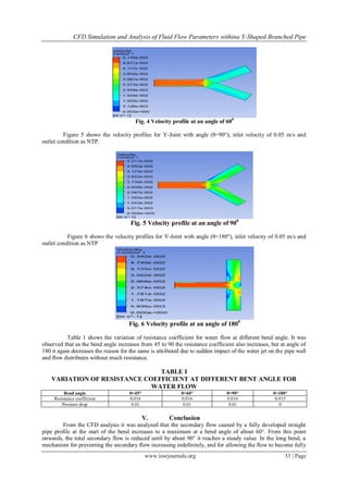
IV. CFD RESULT AND DISCUSSION
The CFD analysis for the Y shape pipe joint was done using ANSYS CFX, for four angles 450
, 60°,
90° and 180° was selected in the current work. The angle 180°converts the wye joint into T- joint. Figure 3
shows the velocity profiles for Y-Joint with angle (θ=45°), inlet velocity of 0.05 m/s and outlet condition as
NTP.
Fig. 3 Velocity profile at an angle of 450
Figure 4 shows the velocity profiles for Y-Joint with angle (θ=60°), inlet velocity of 0.05 m/s and
outlet condition as NTP.](https://image.slidesharecdn.com/f01013134-150120223643-conversion-gate02/85/CFD-Simulation-and-Analysis-of-Fluid-Flow-Parameters-within-a-Y-Shaped-Branched-Pipe-2-320.jpg)
![CFD Simulation and Analysis of Fluid Flow Parameters withina Y-Shaped Branched Pipe
www.iosrjournals.org 34 | Page
developed, is provided by the formation of total pressure gradients, opposite in sign to those at the start of the
bend, and the consequent production of vorticity of opposite rotational sense.When the bend is increases beyond
90° so that this negative vorticity becomes positive, the secondary flow tends to increase. An important outcome
of the CFD analysis which validates the practical application of wye pipe at bend angle of 45° was the resistance
coefficient which comes out to be zero
REFERENCES
[1] Romero-Gomez, P., C. K. Ho, and C. Y. Choi. (2008). Mixing at Cross Junctions in Water Distribution Systems – Part I. A
Numerical Study, ASCE Journal of Water Resources Planning and Management, 134:3, pp. 284-294.
[2] Austin, R. G., B. van B. Wanders, S. McKenna and C. Y. Choi. (2008) Mixing at Cross Junctions in Water Distribution Systems –
Part II. An Experimental Study, ASCE Journal of Water Resources Planning and Management 134:3 pp. 295-302.
[3] Ho, C. K. Solute Mixing Models for Water Distribution Pipe Networks. ASCE Journal of Hydraulic Engineering. Vol. 33, Issue 3,
pp.830-836, 2008
[4] Anand, R.B., Sandeep, Reflect of angle of turn on flow characteristics of Y-shaped diffusing duct using CFD, Frontiers in
Automobile and Mechanical Engineering (FAME), 2010, 25-27 Nov. 2010.
[5] R.B. Anand, A. Chandraprabhu, X.J.A. Richards, N. Hares ram, Flow and performance characteristics of a Y-shaped diffusing duct
using CFD, International Journal of Aerodynamics 2010 - Vol. 1, No.2 pp. 115 - 129.
[6] B.J.Mc Keon, M.V.Zagarola, A.J.Smits, A new friction factor relationship for fully developed pipe flow, J. Fluid Mech. (2005), vol.
538, pp. 429–443
[7] Gyorgy, Pinho, and Maia, 2006. “The effect of corner radius on the energy loss in 90 ̊ tee junction turbulent flows”. Department of
civil engineering, Faculty of Engineering, University of Porto](https://image.slidesharecdn.com/f01013134-150120223643-conversion-gate02/85/CFD-Simulation-and-Analysis-of-Fluid-Flow-Parameters-within-a-Y-Shaped-Branched-Pipe-4-320.jpg)

This document presents a computational fluid dynamics (CFD) simulation and analysis of fluid flow parameters within a Y-shaped branched pipe. The study models a Y-shaped pipe branch with three 1-inch diameter pipes of equal length and analyzes flow at bend angles of 45°, 60°, 90°, and 180° using ANSYS CFX software. The results show that the resistance coefficient, which indicates pressure loss, increases with bend angle from 45° to 90° but then decreases at 180° due to flow redistributing with less resistance. In conclusion, the CFD analysis validates the practical application of a Y-pipe at a 45° bend angle which results in a resistance coefficient of zero.