Downloaded 58 times
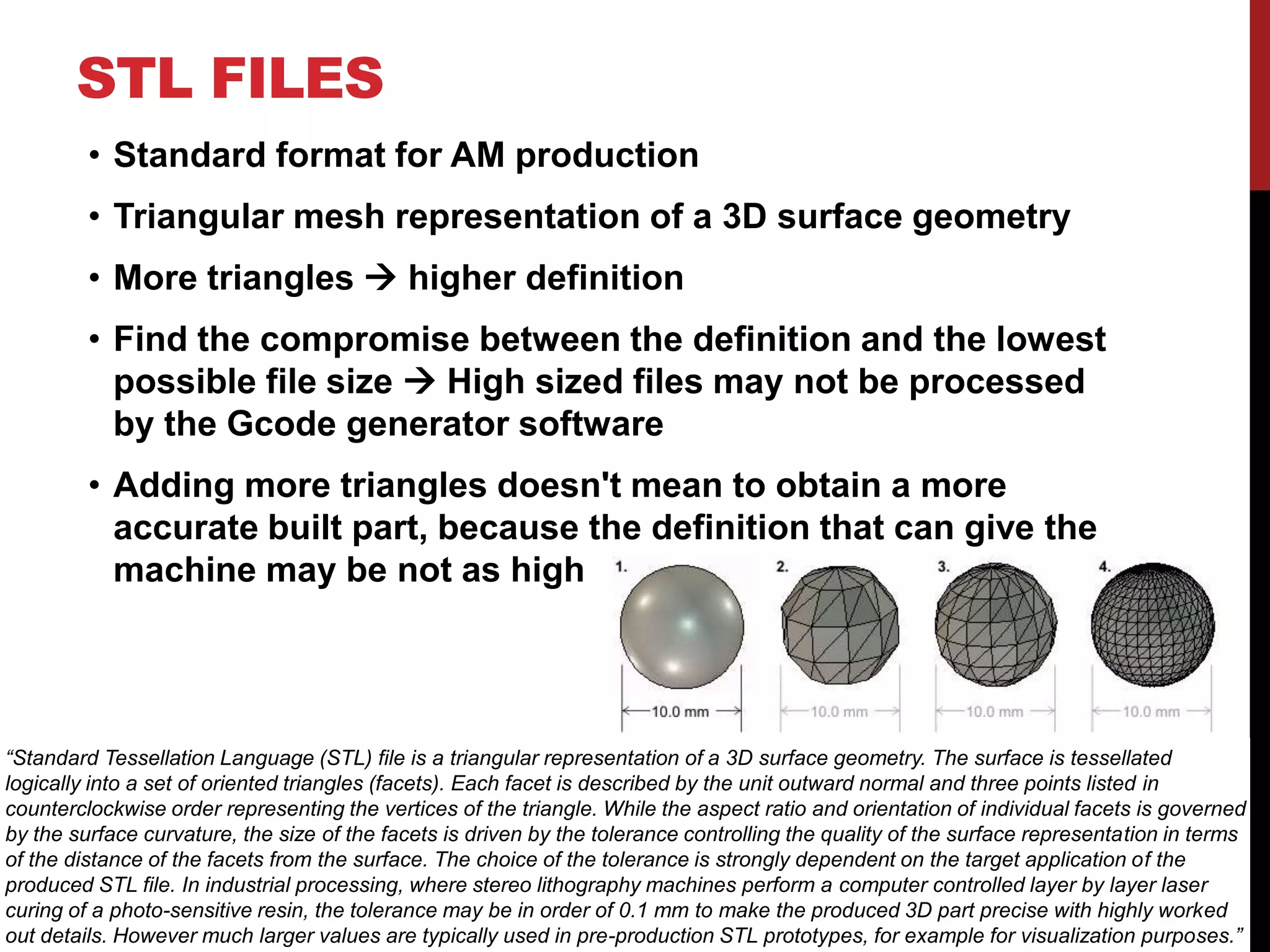
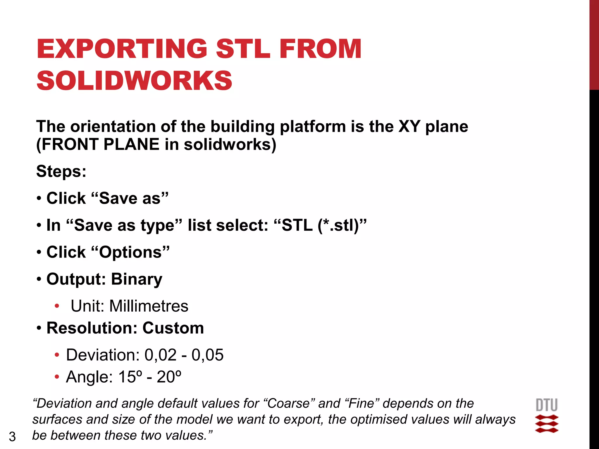
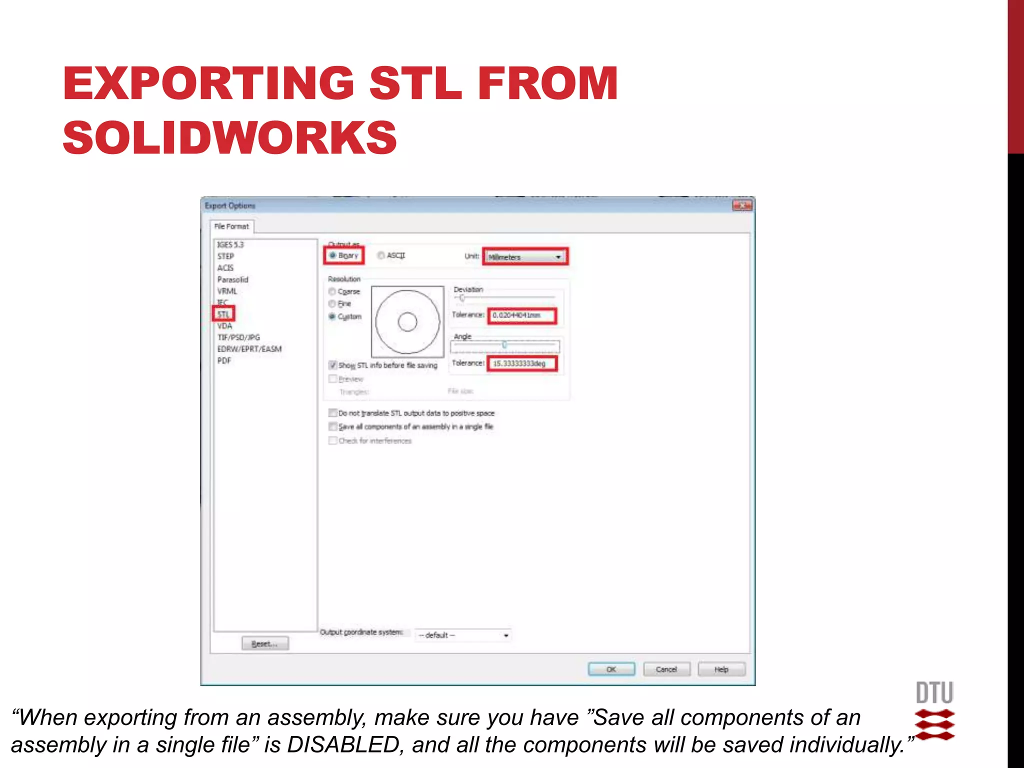
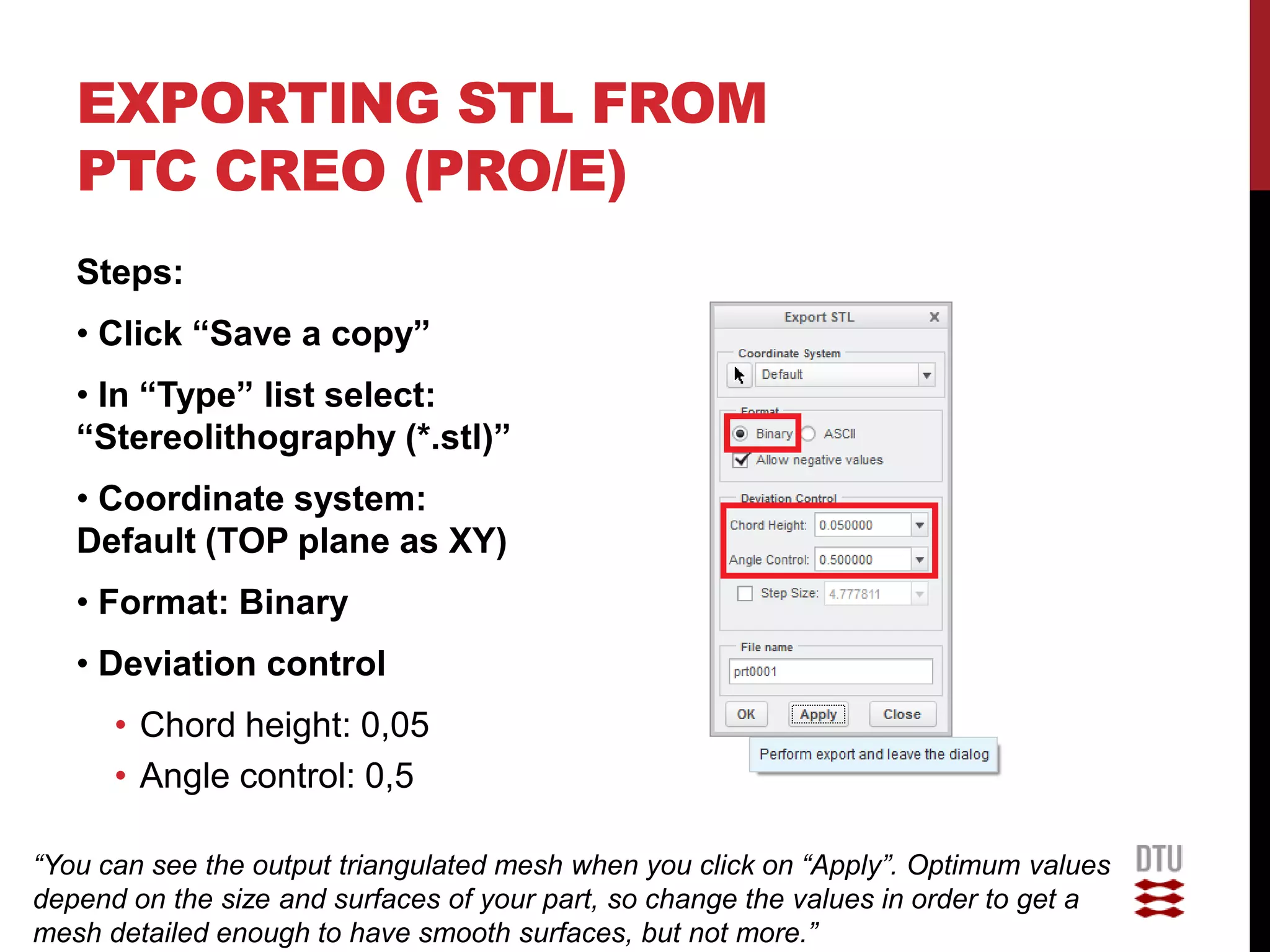

Standard Tessellation Language (STL) files represent a 3D surface as a set of triangular facets and are commonly used for 3D printing and additive manufacturing. When exporting a CAD model to an STL file, it is important to balance the triangle count and file size by adjusting the resolution settings. A higher resolution with more triangles provides more detail but a larger file, while too low a resolution risks losing important surface details in the 3D printed part. Proper STL export settings depend on the complexity of the model surfaces and size.