Download as PDF, PPTX
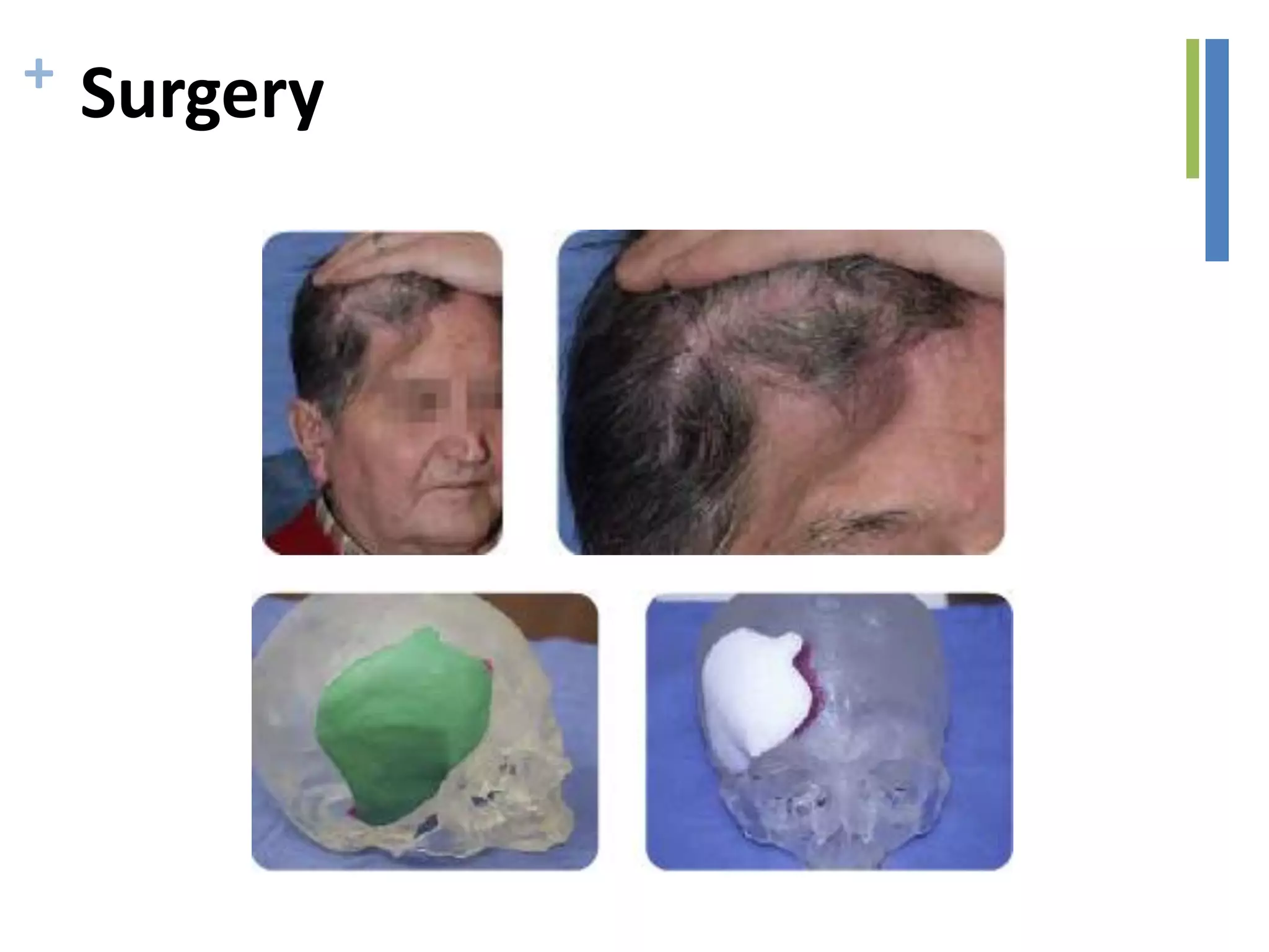
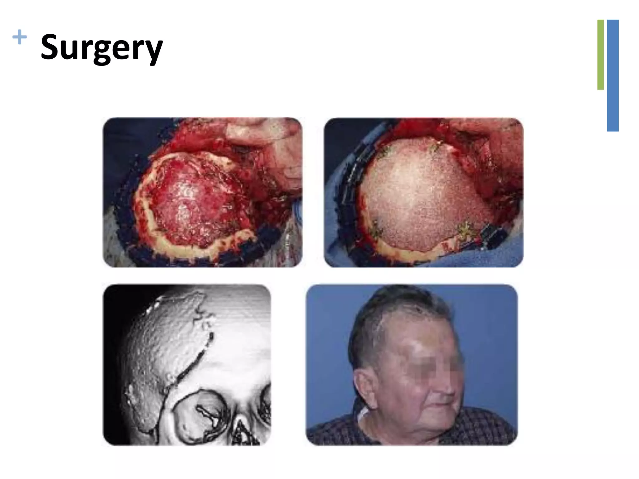
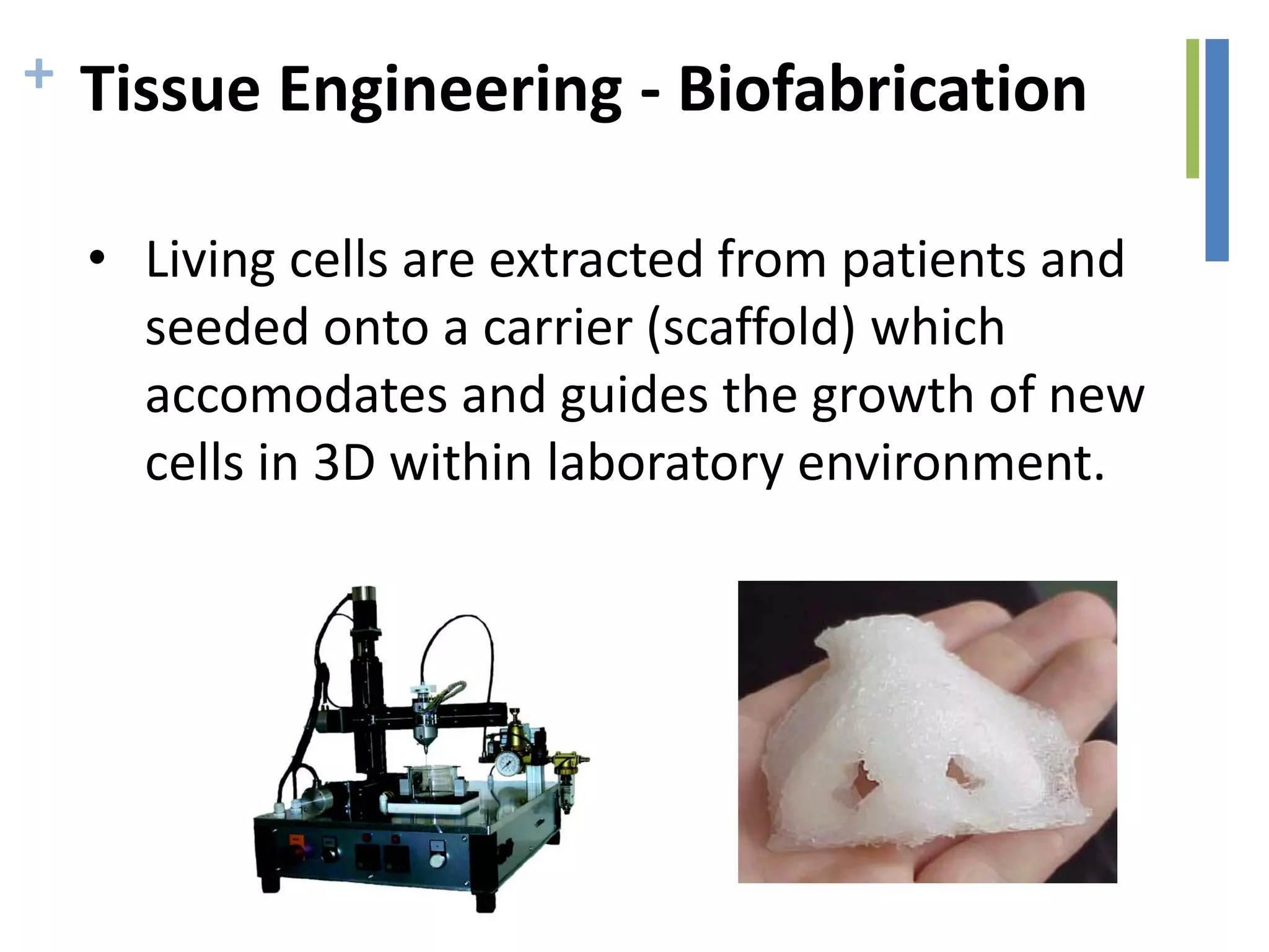
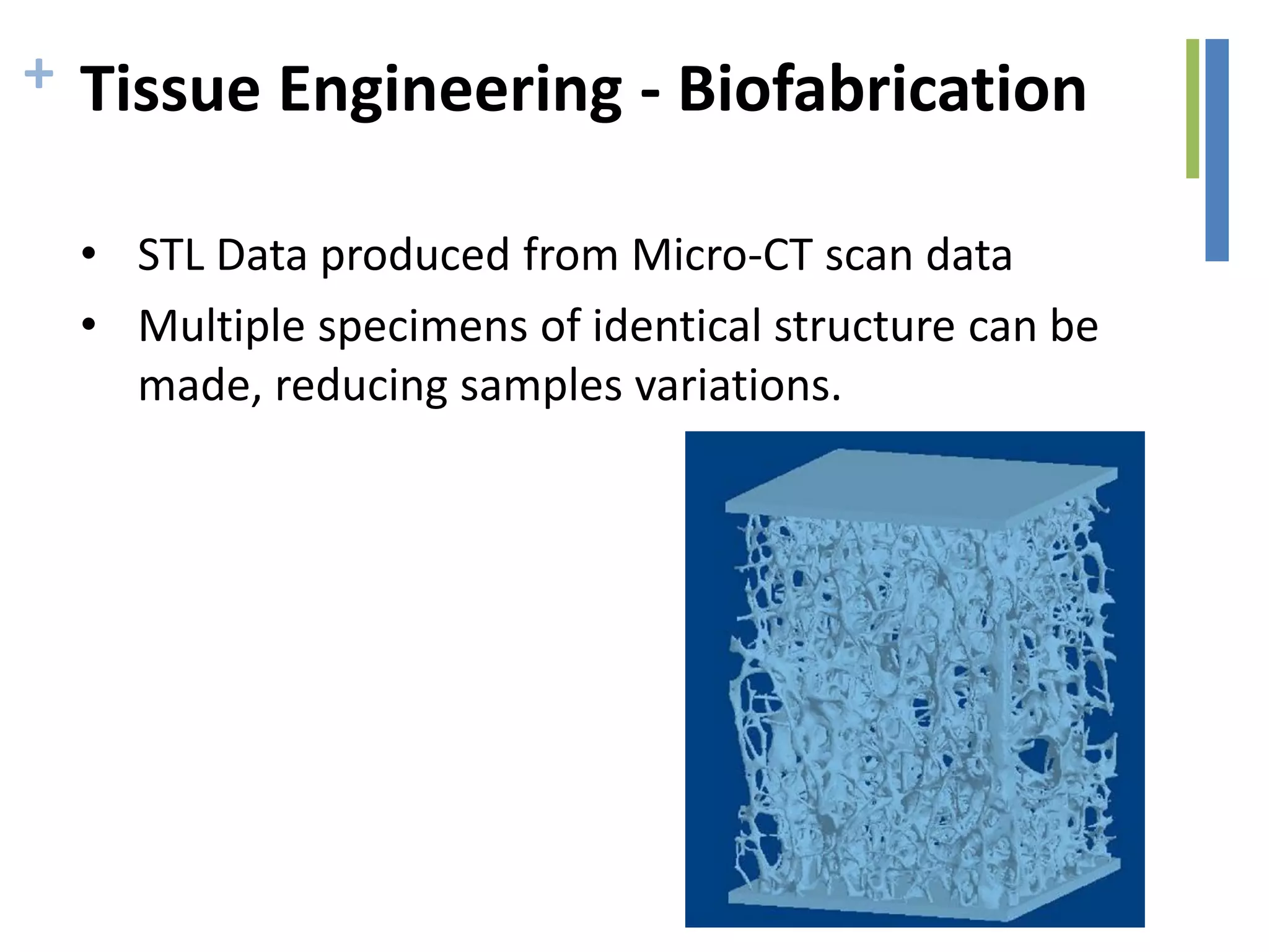

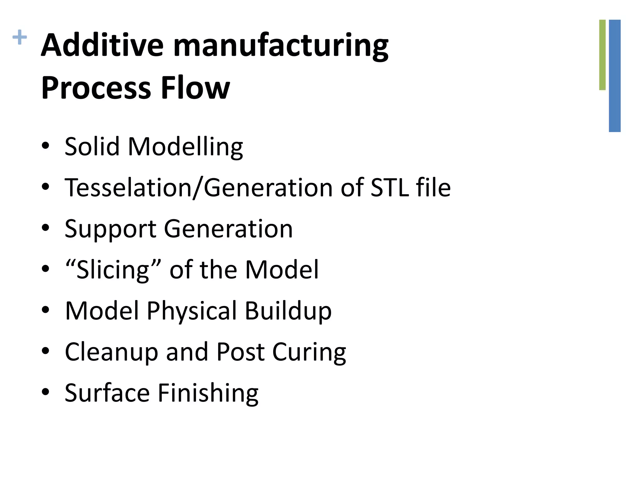
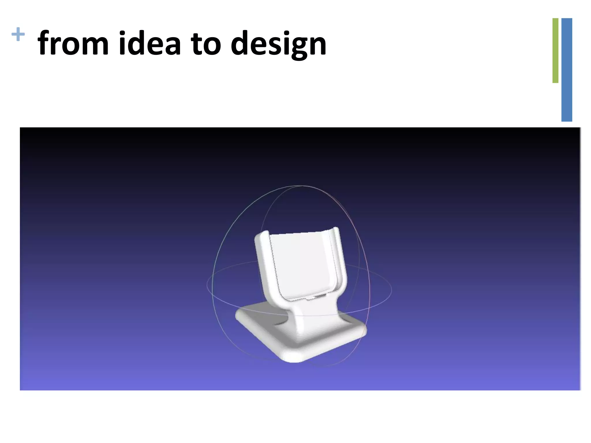
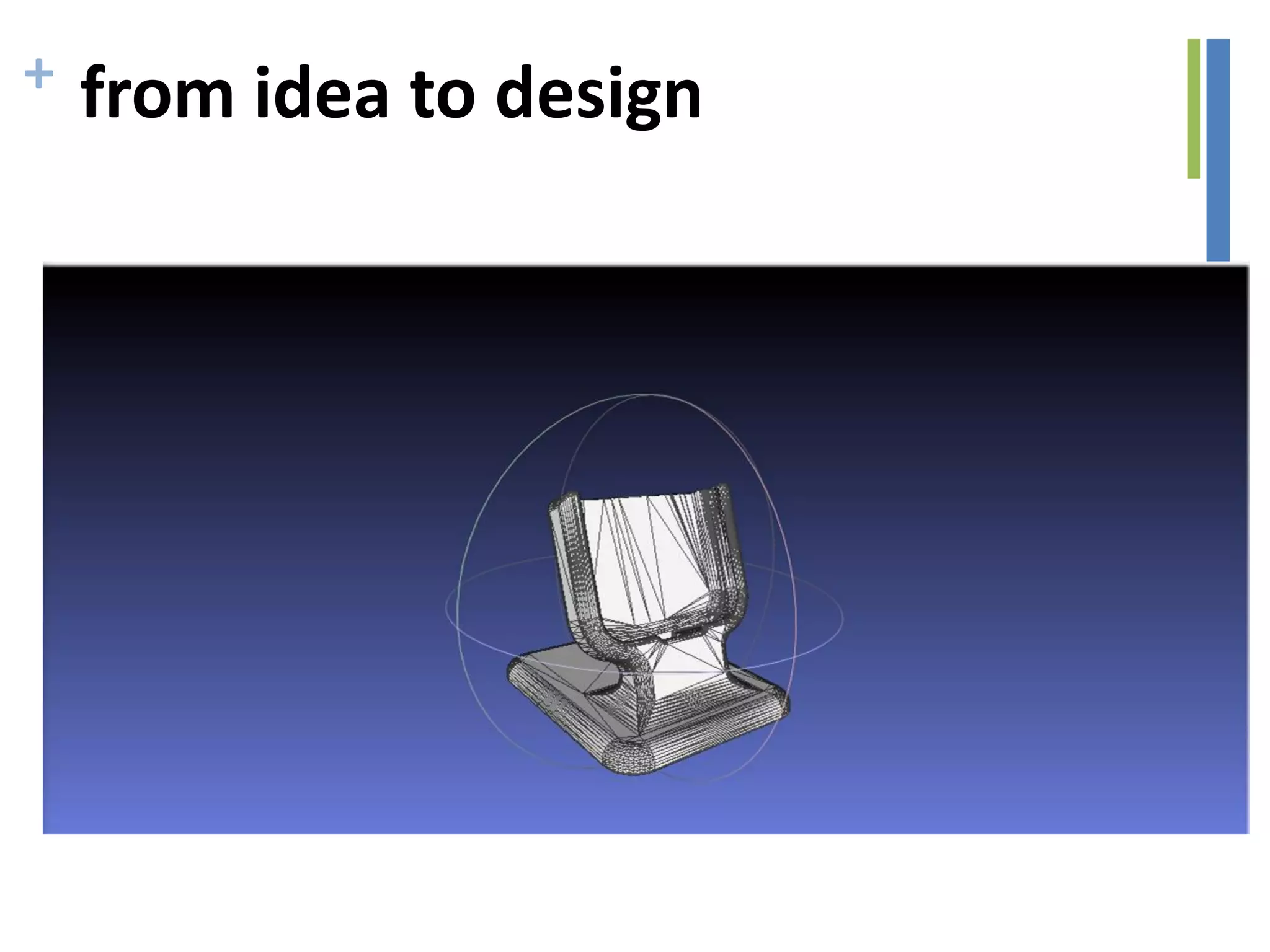
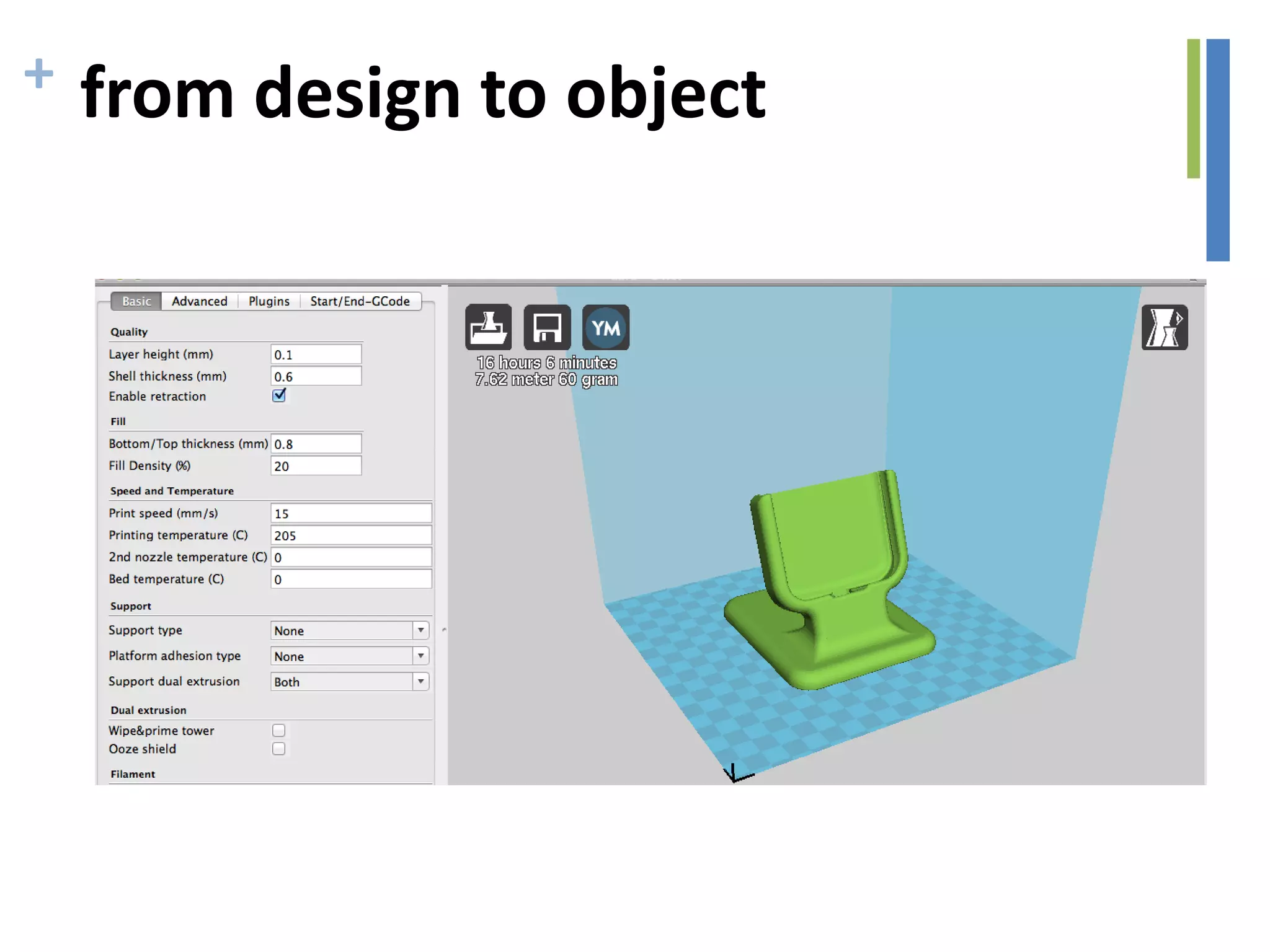
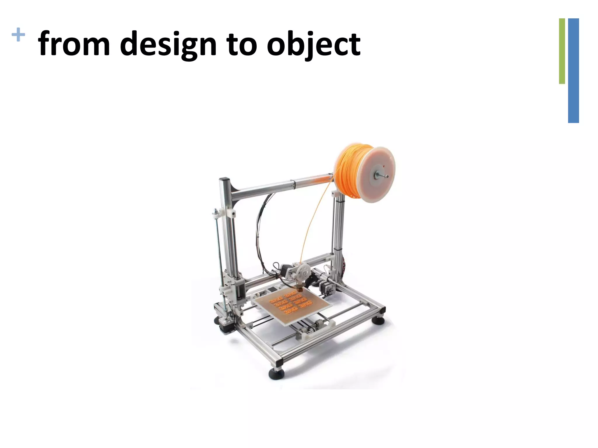
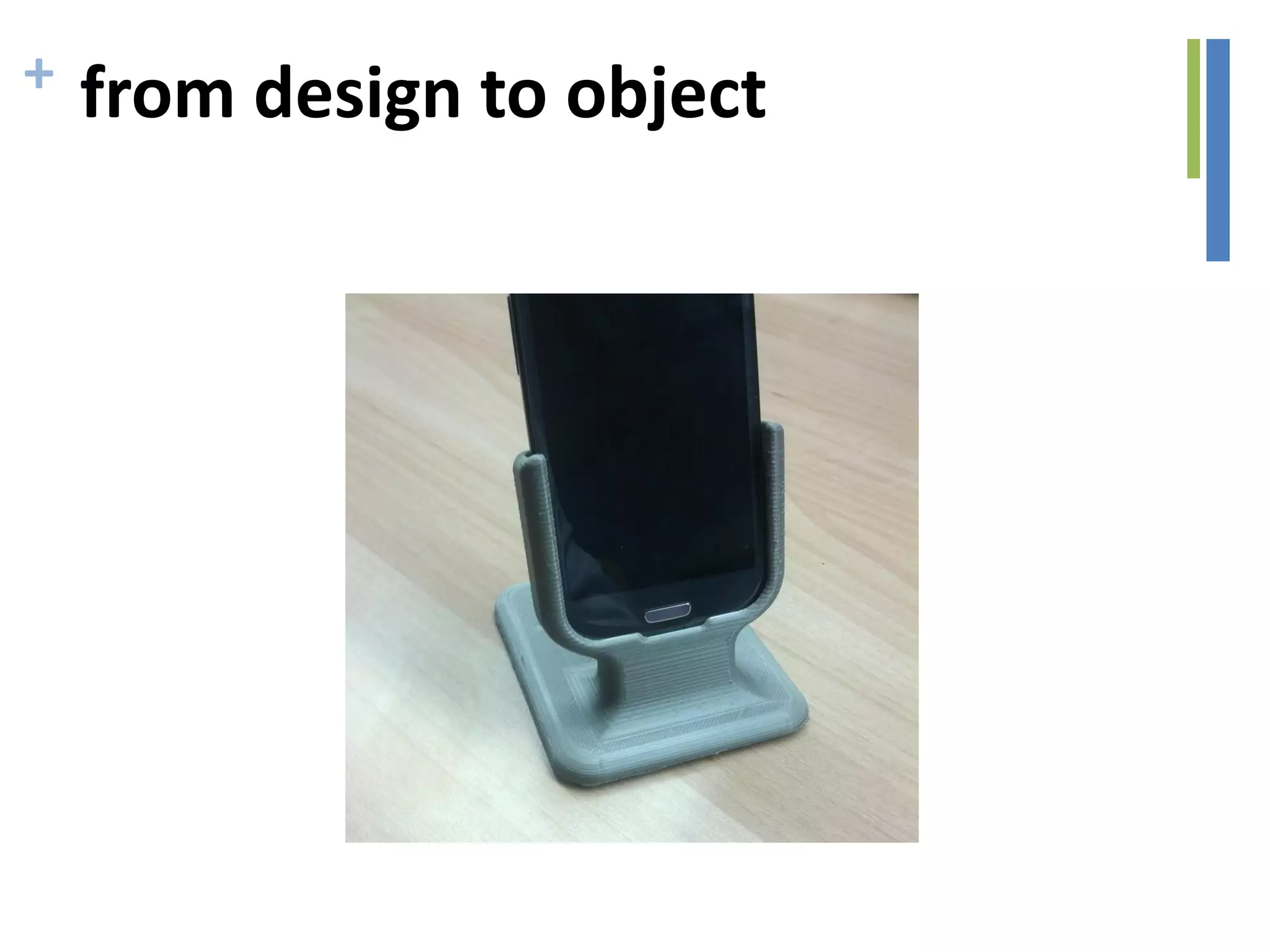
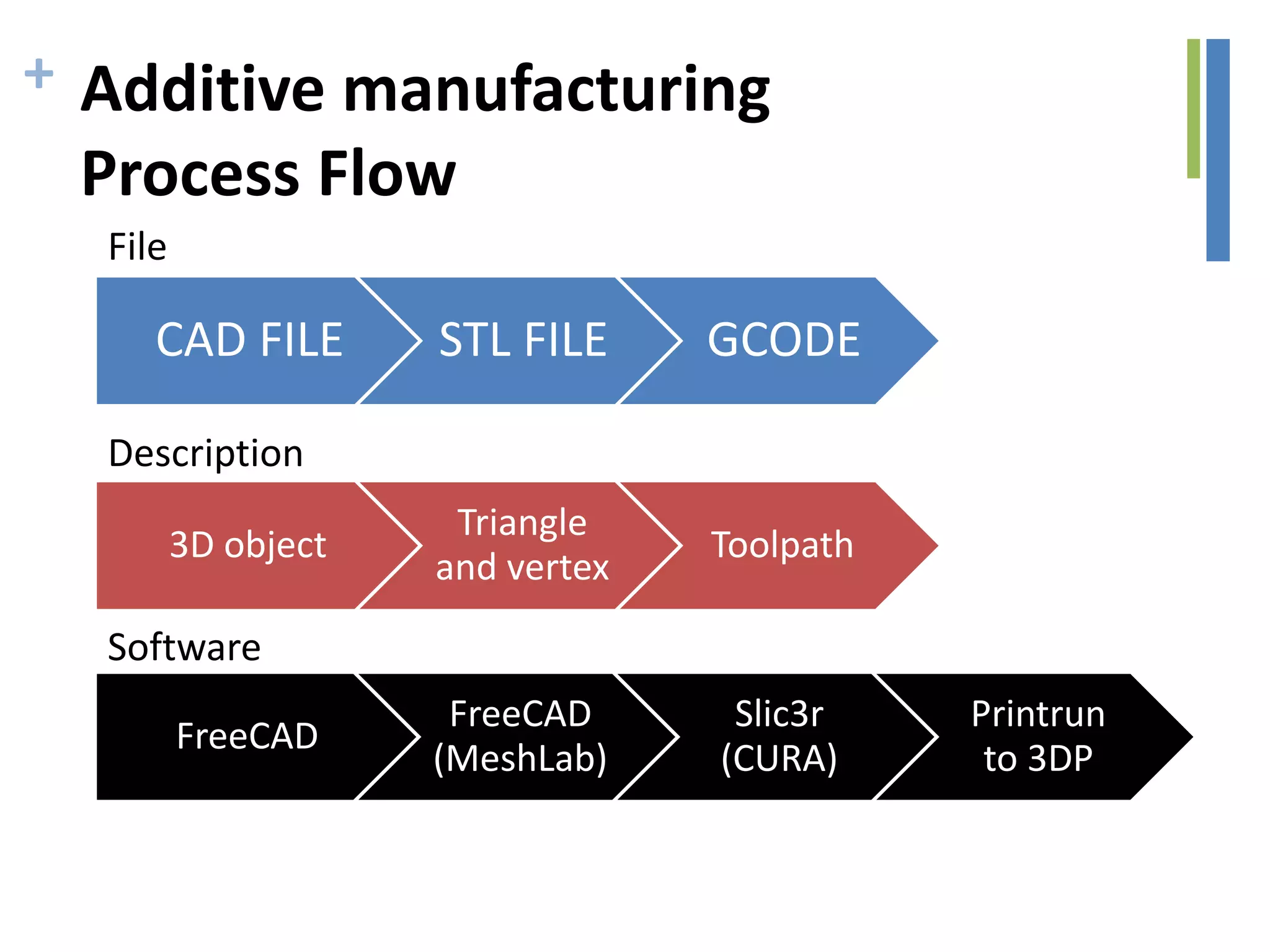
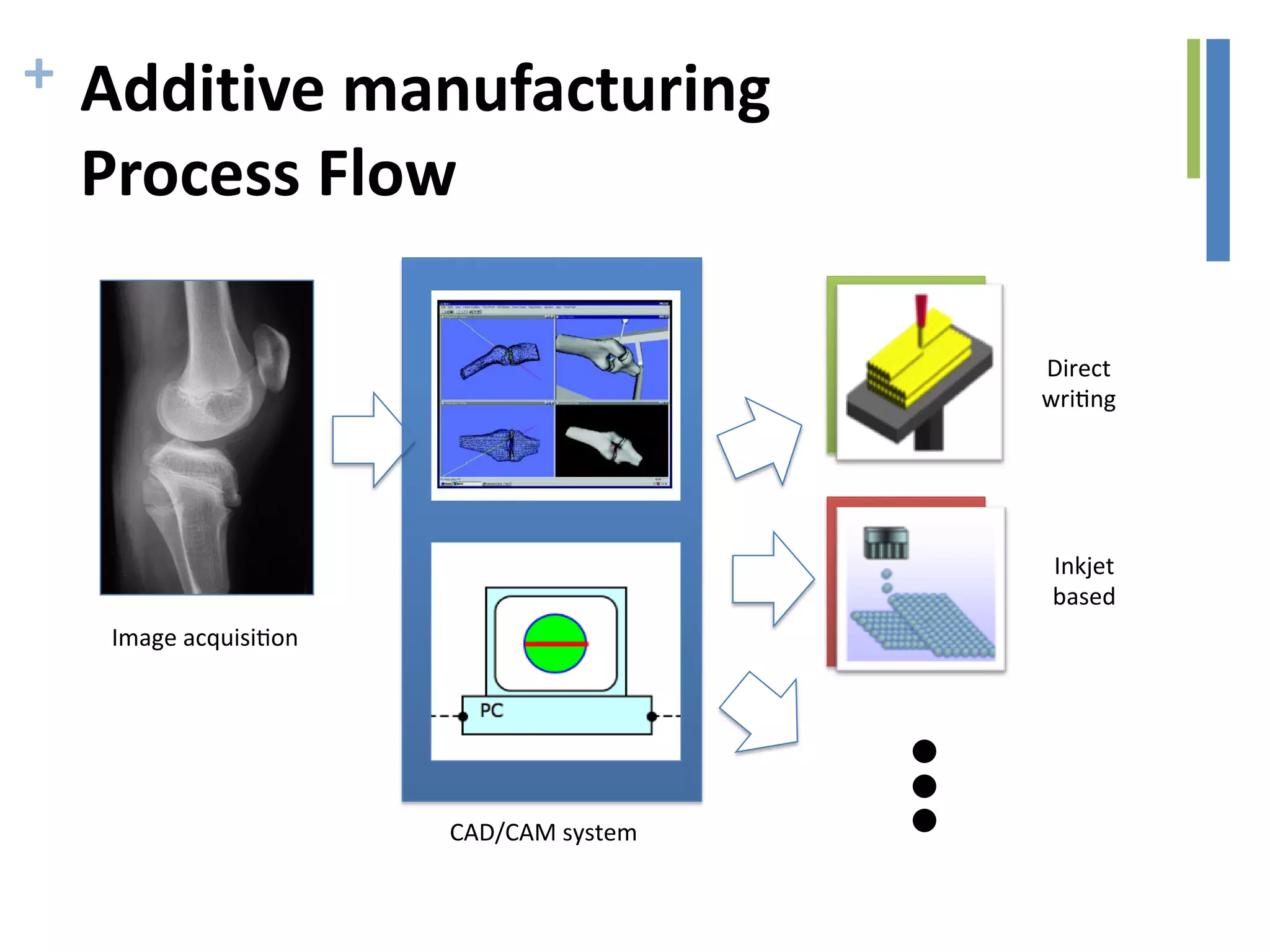

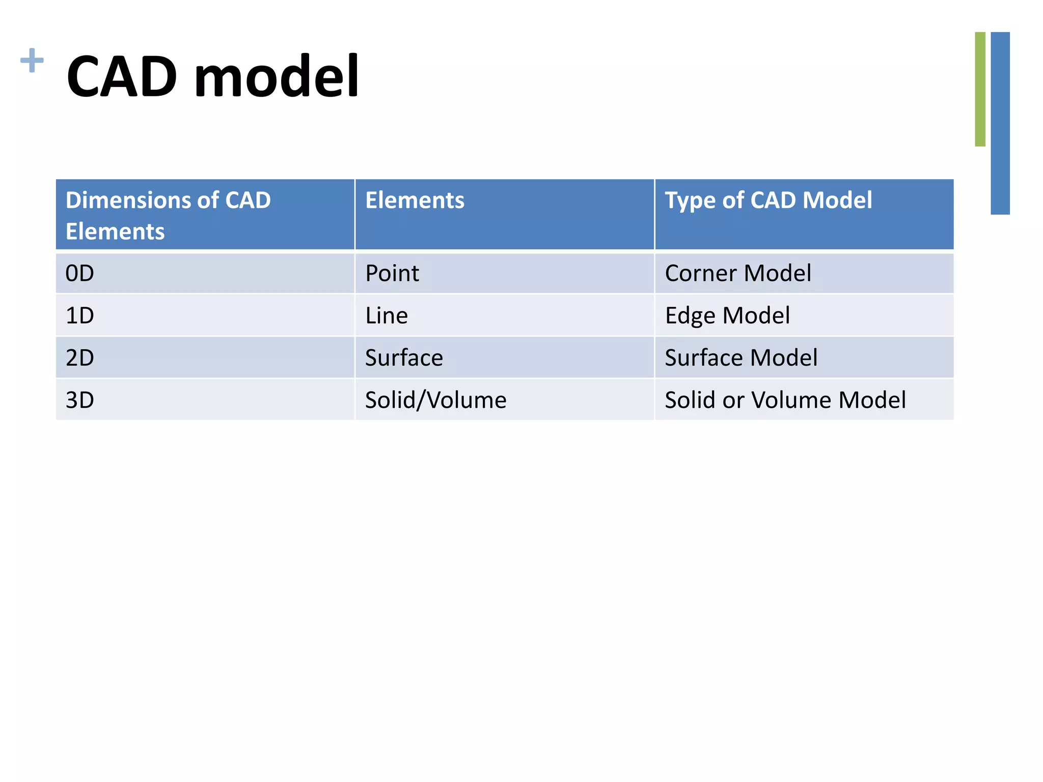
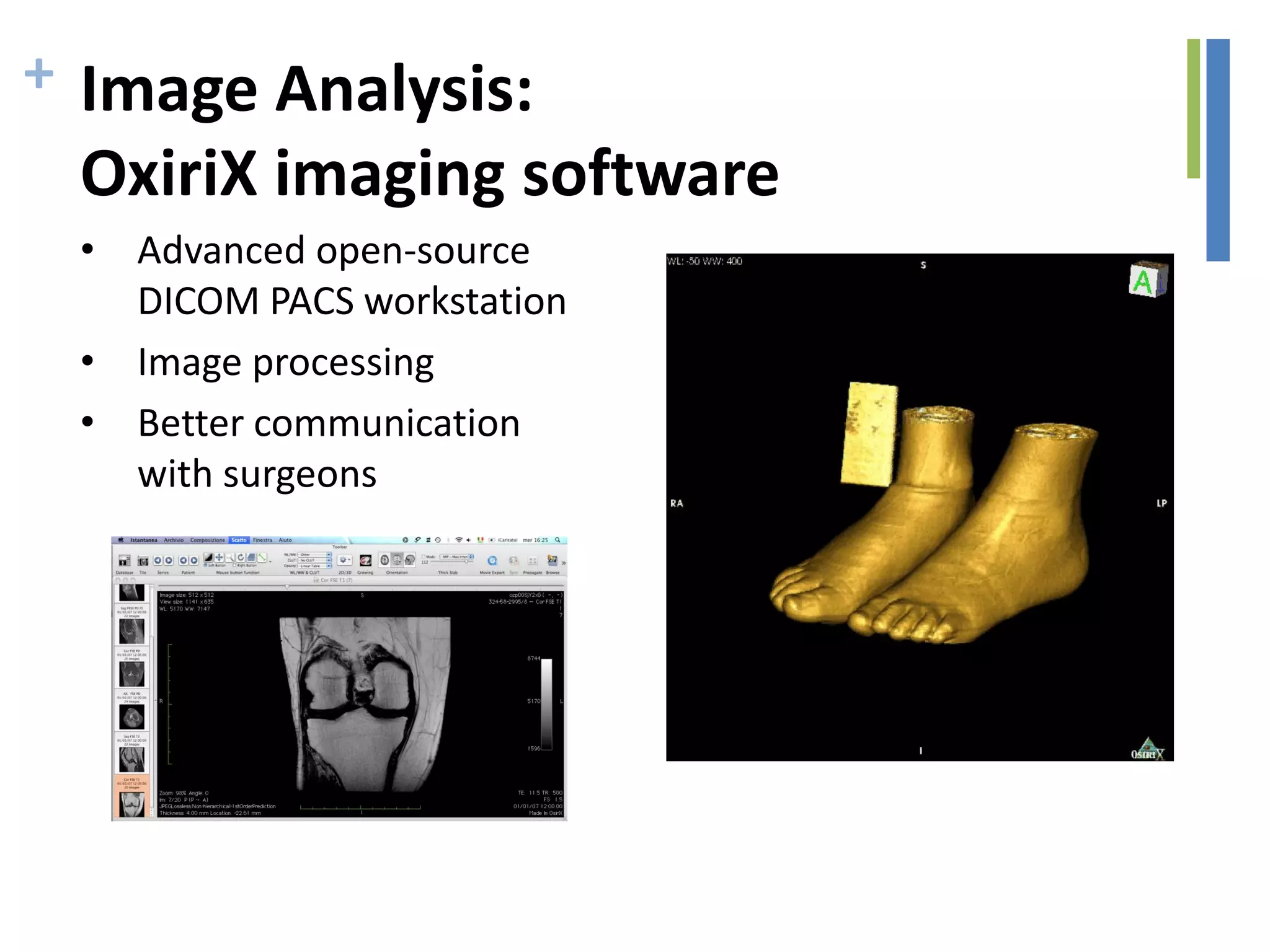
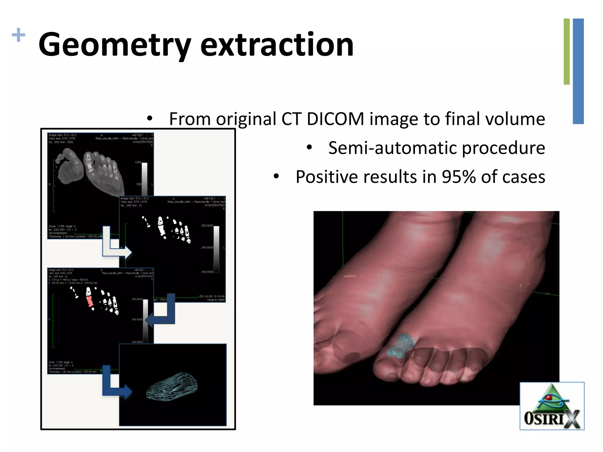


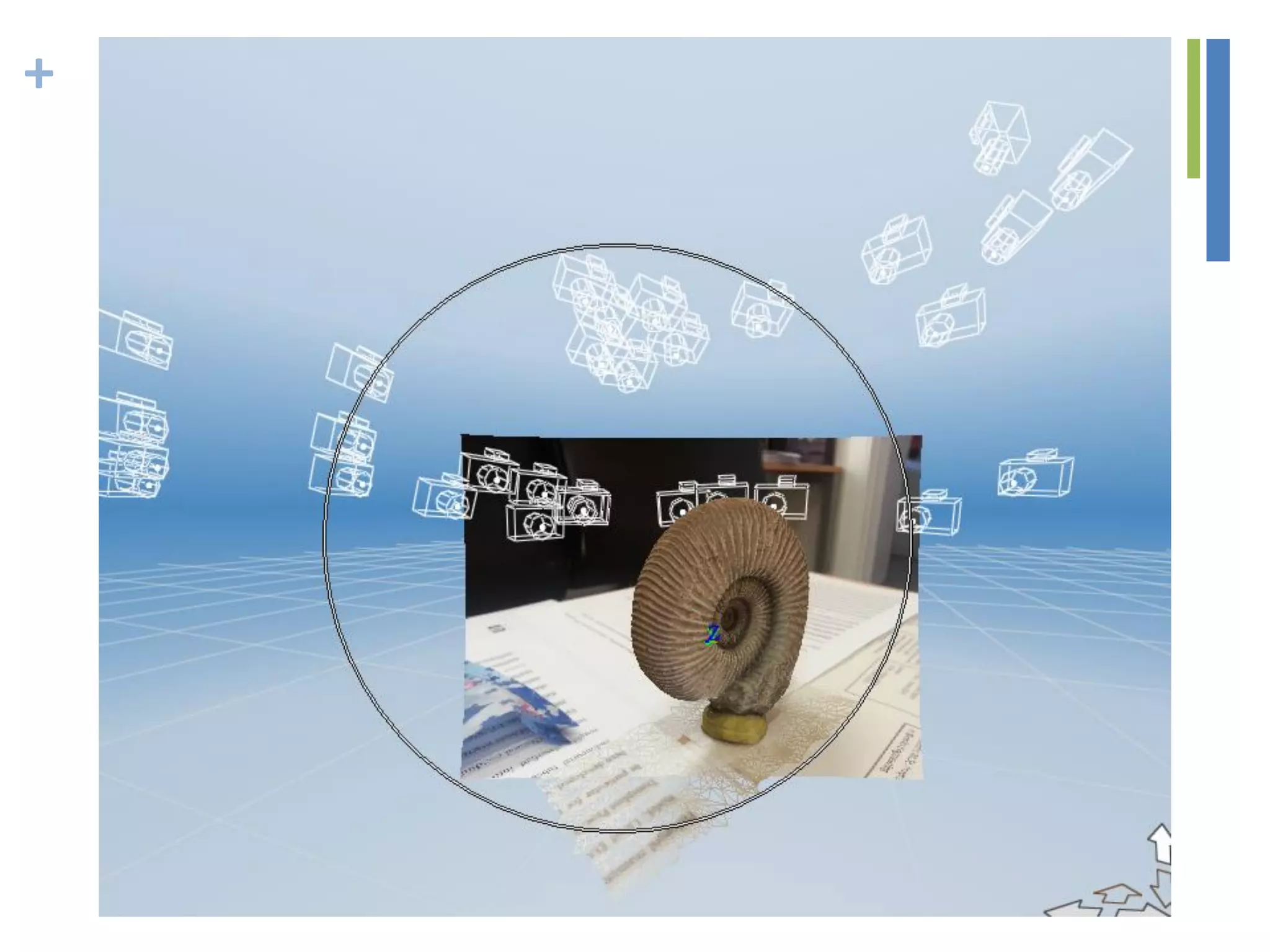
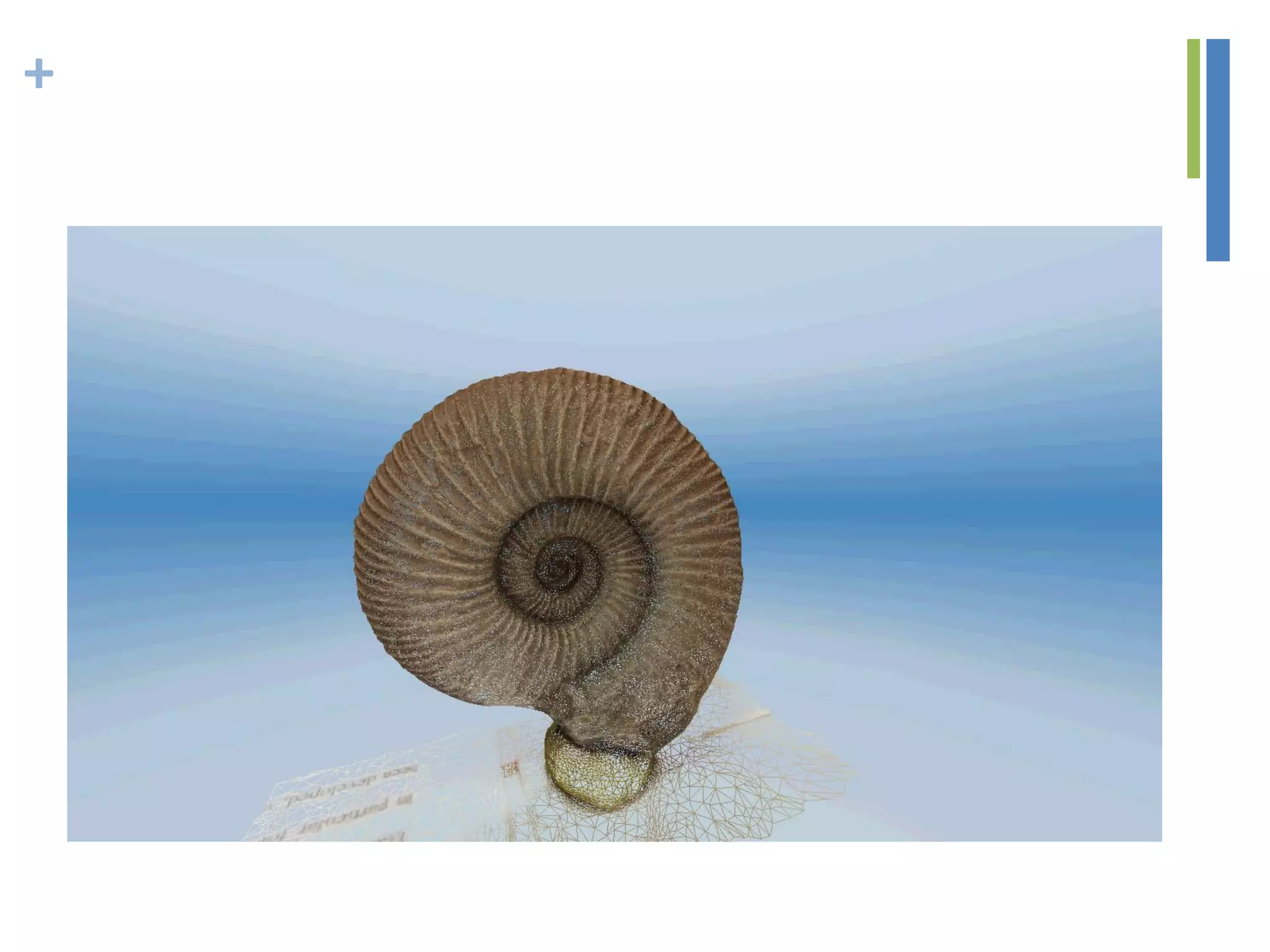
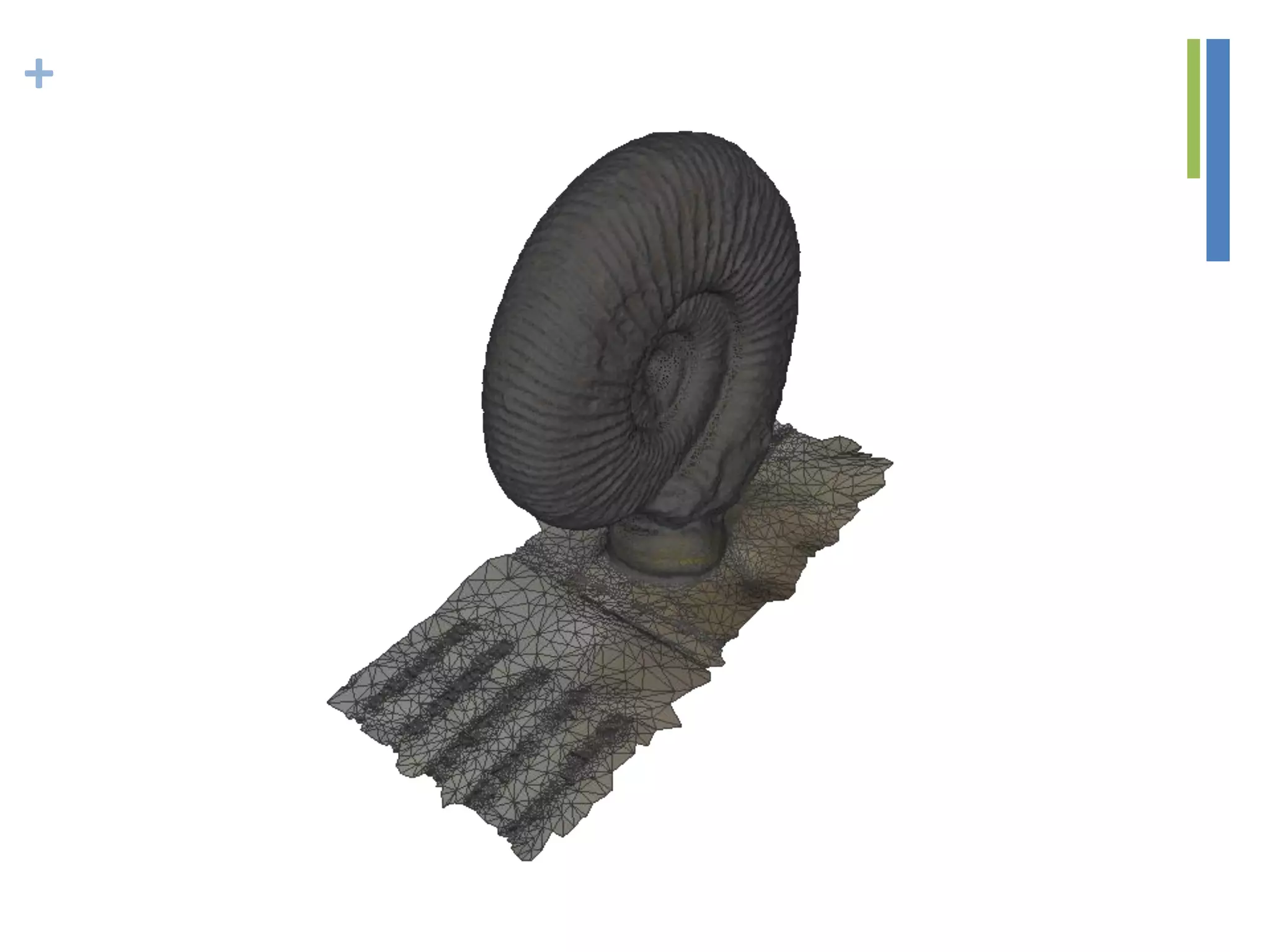
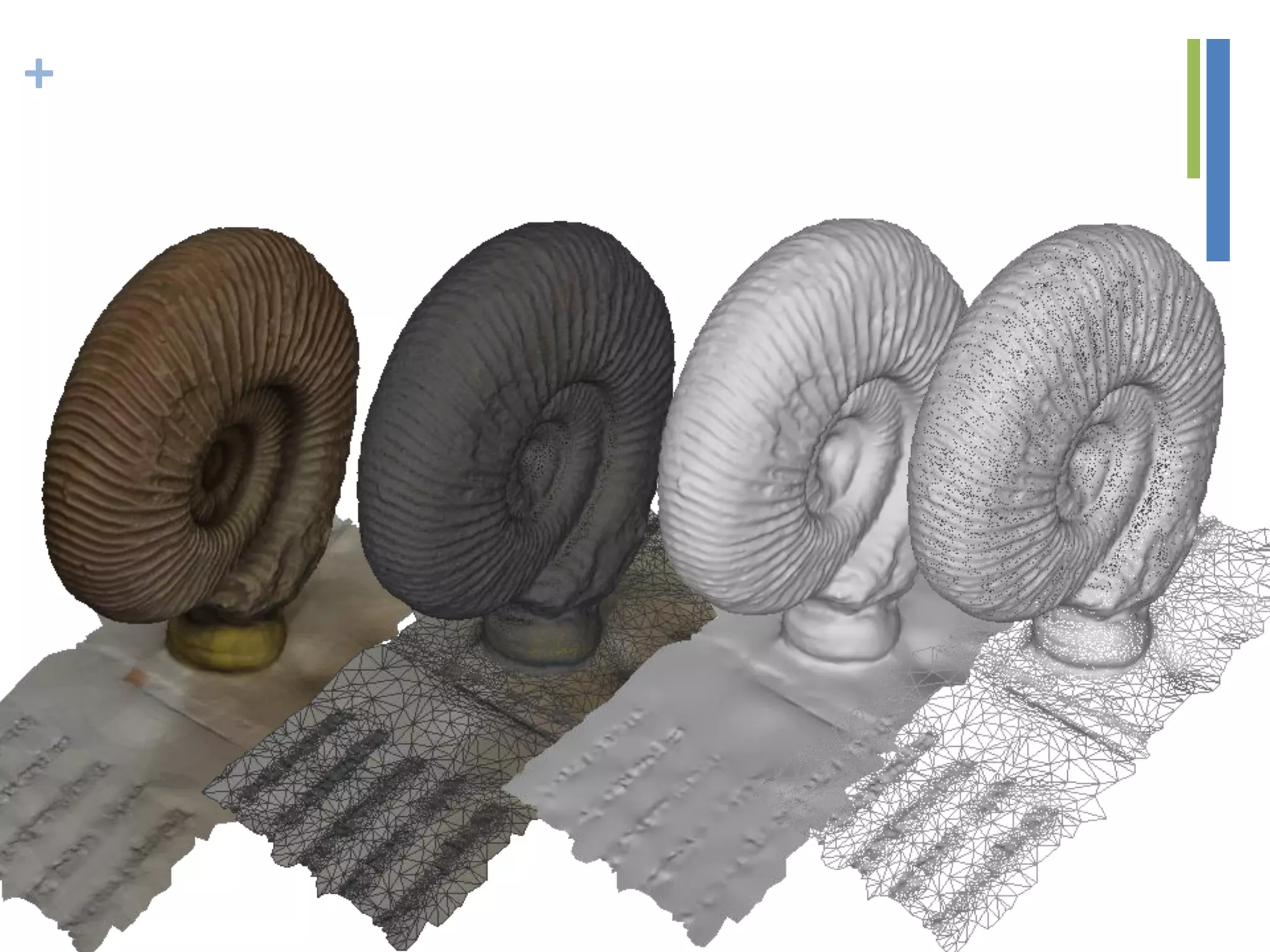
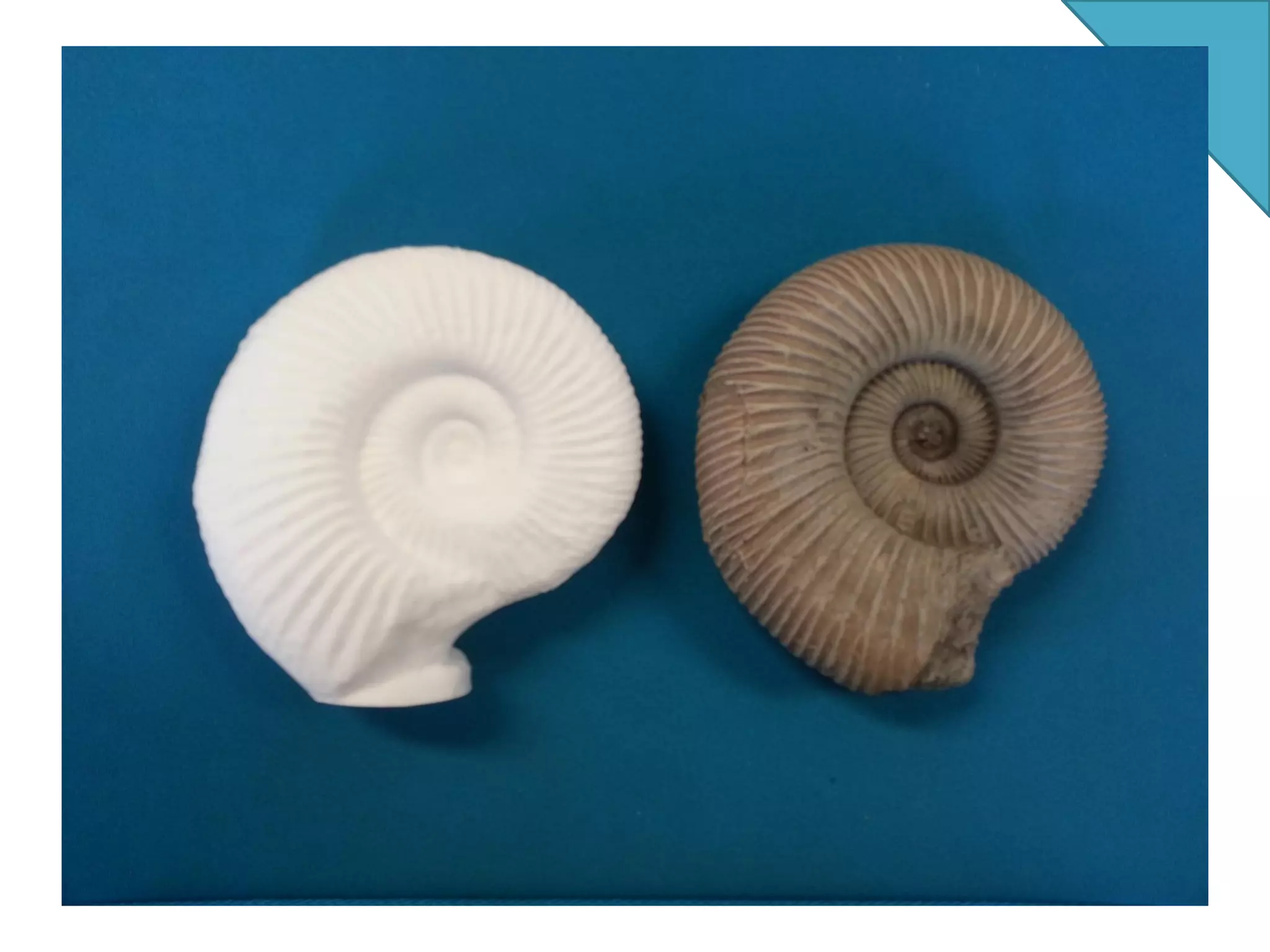
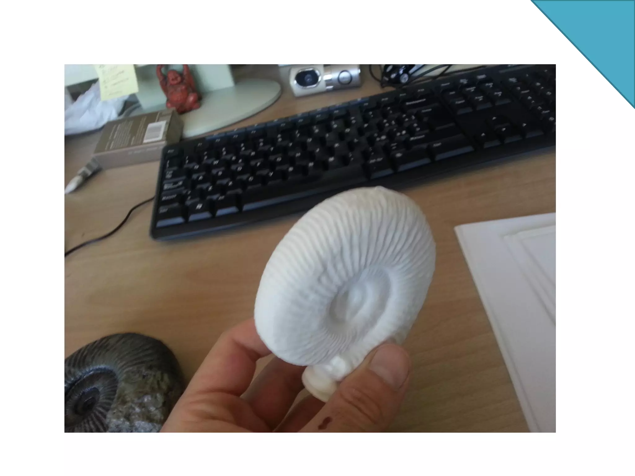

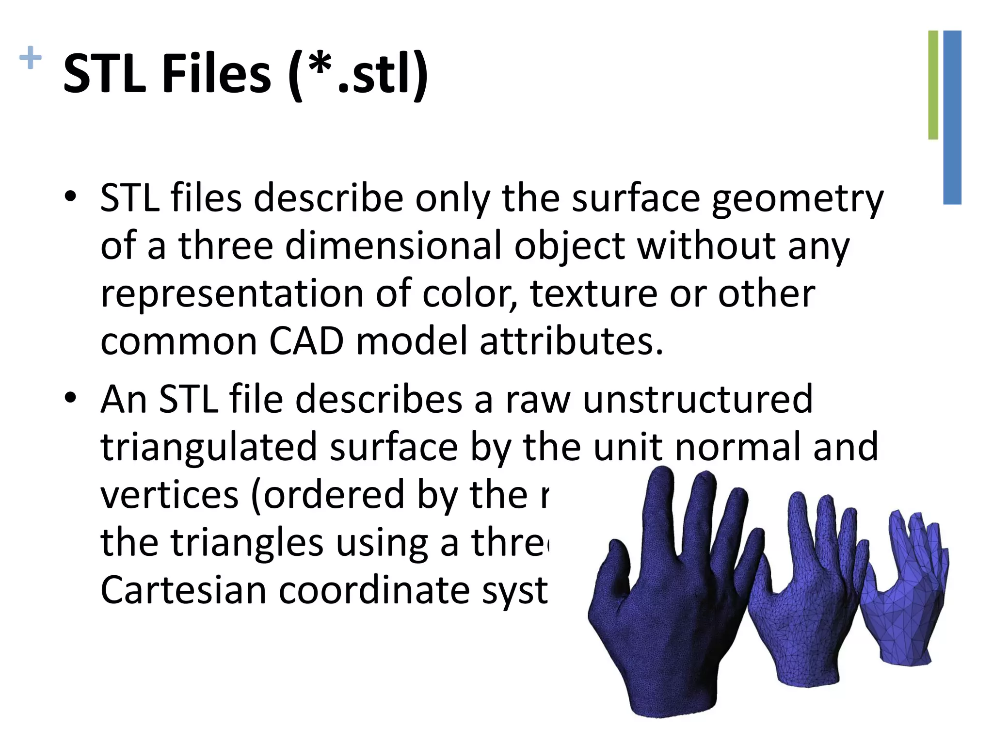
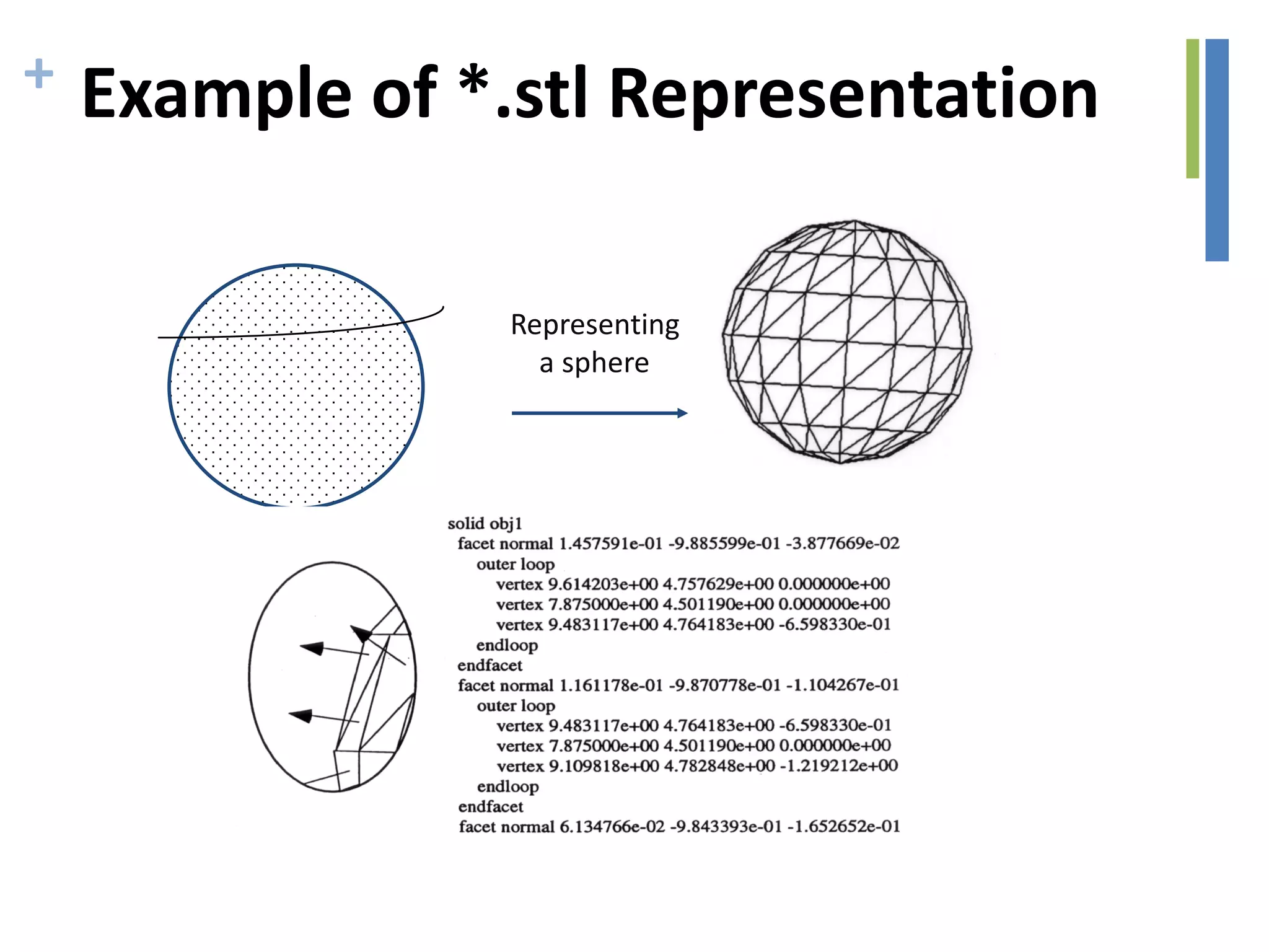
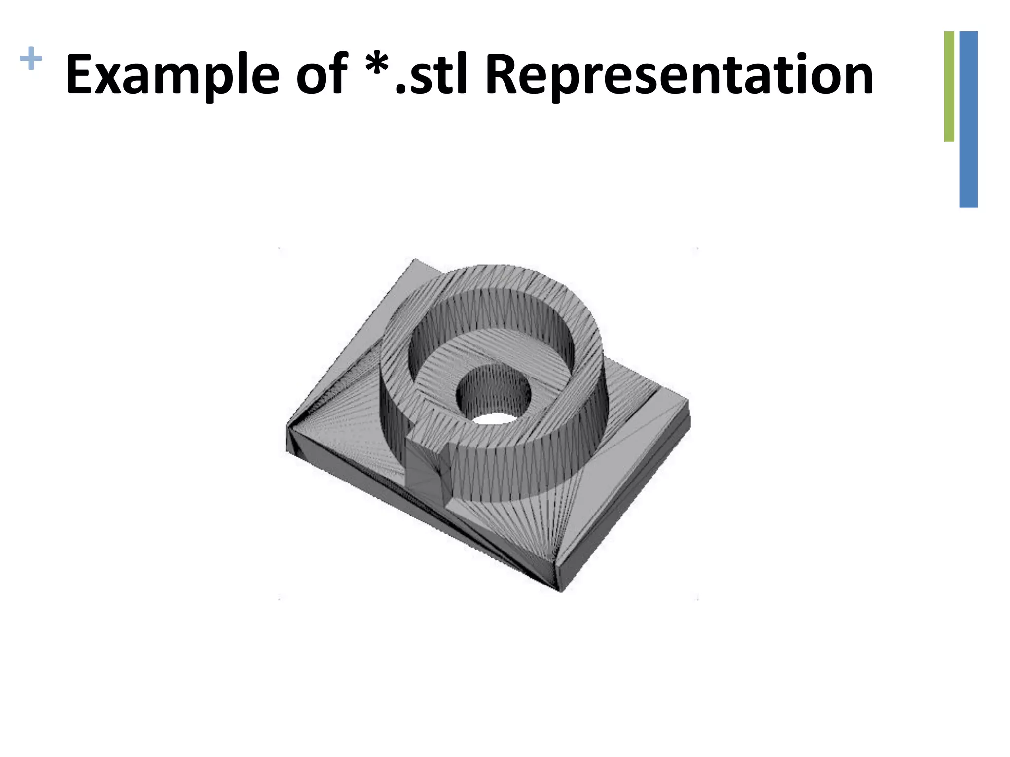
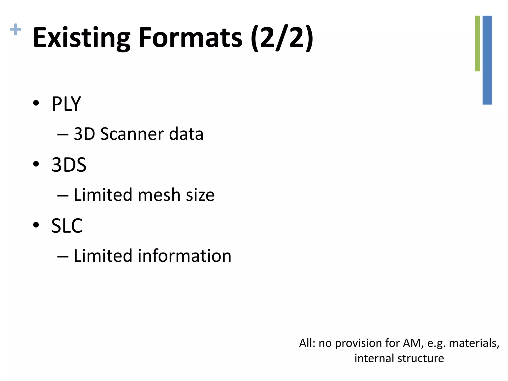
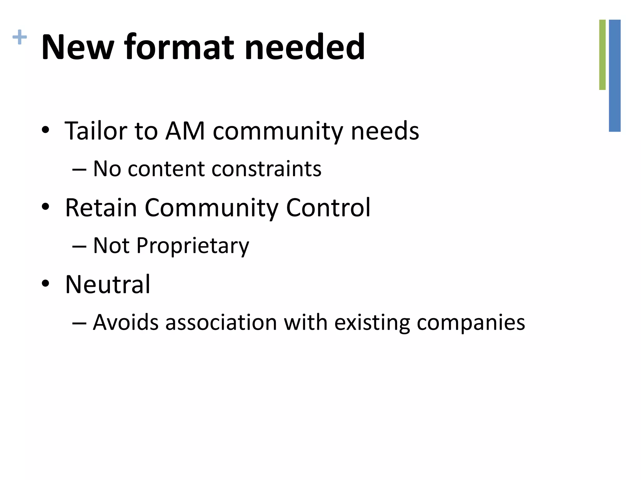
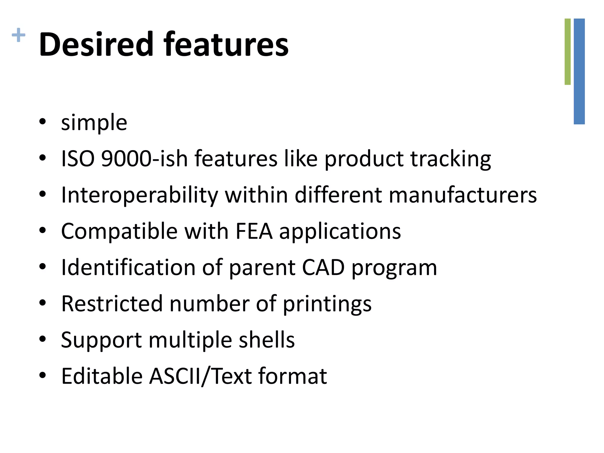
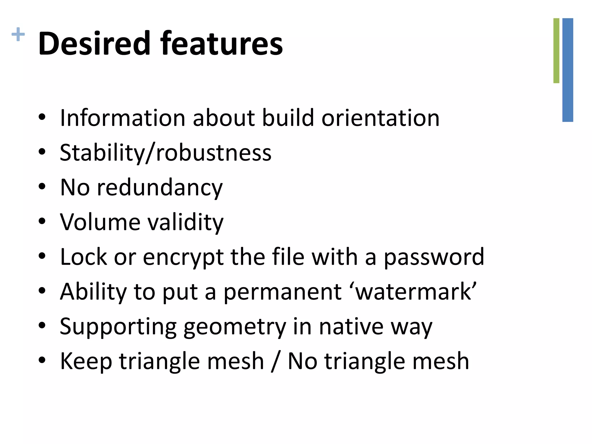
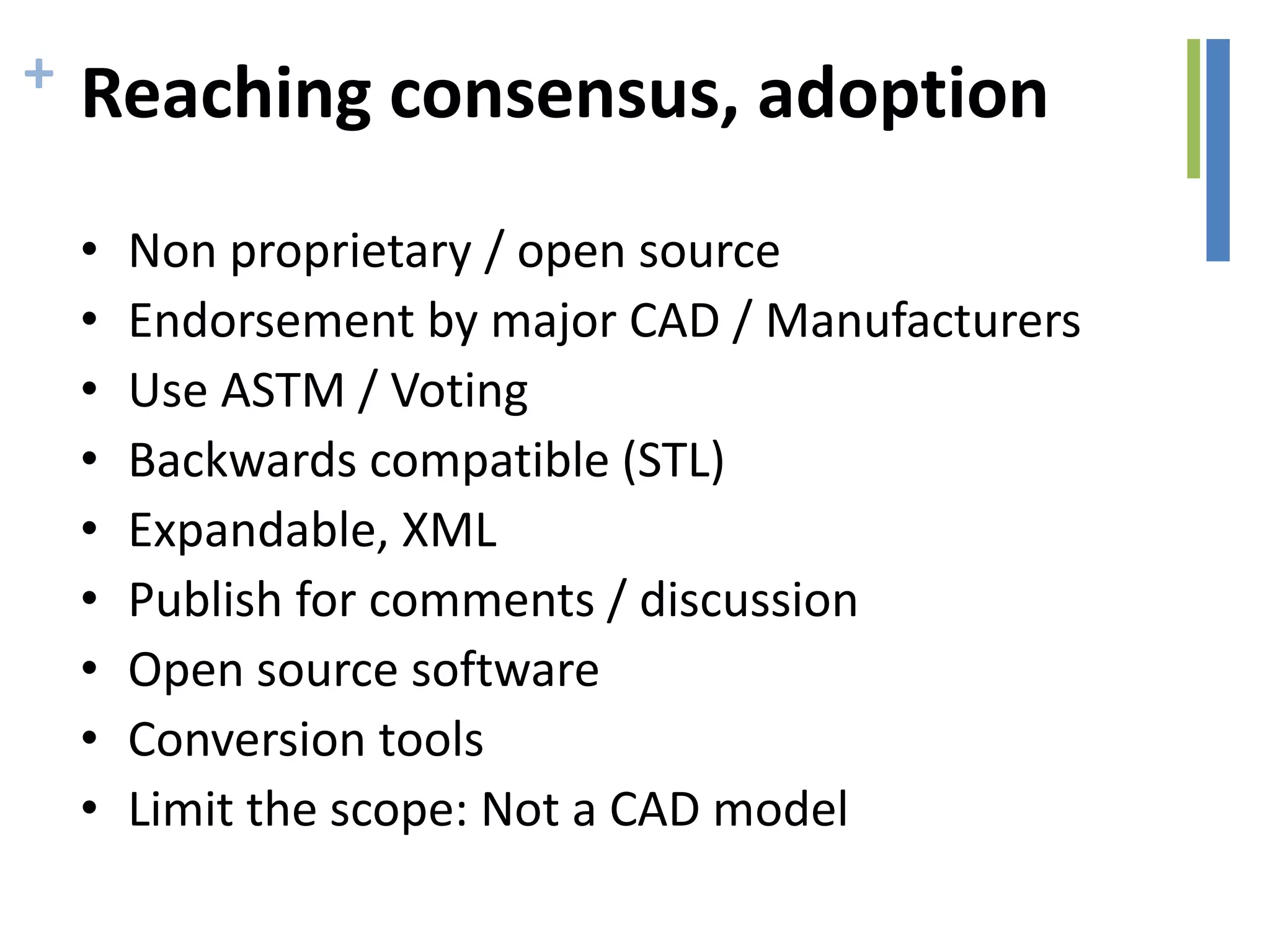
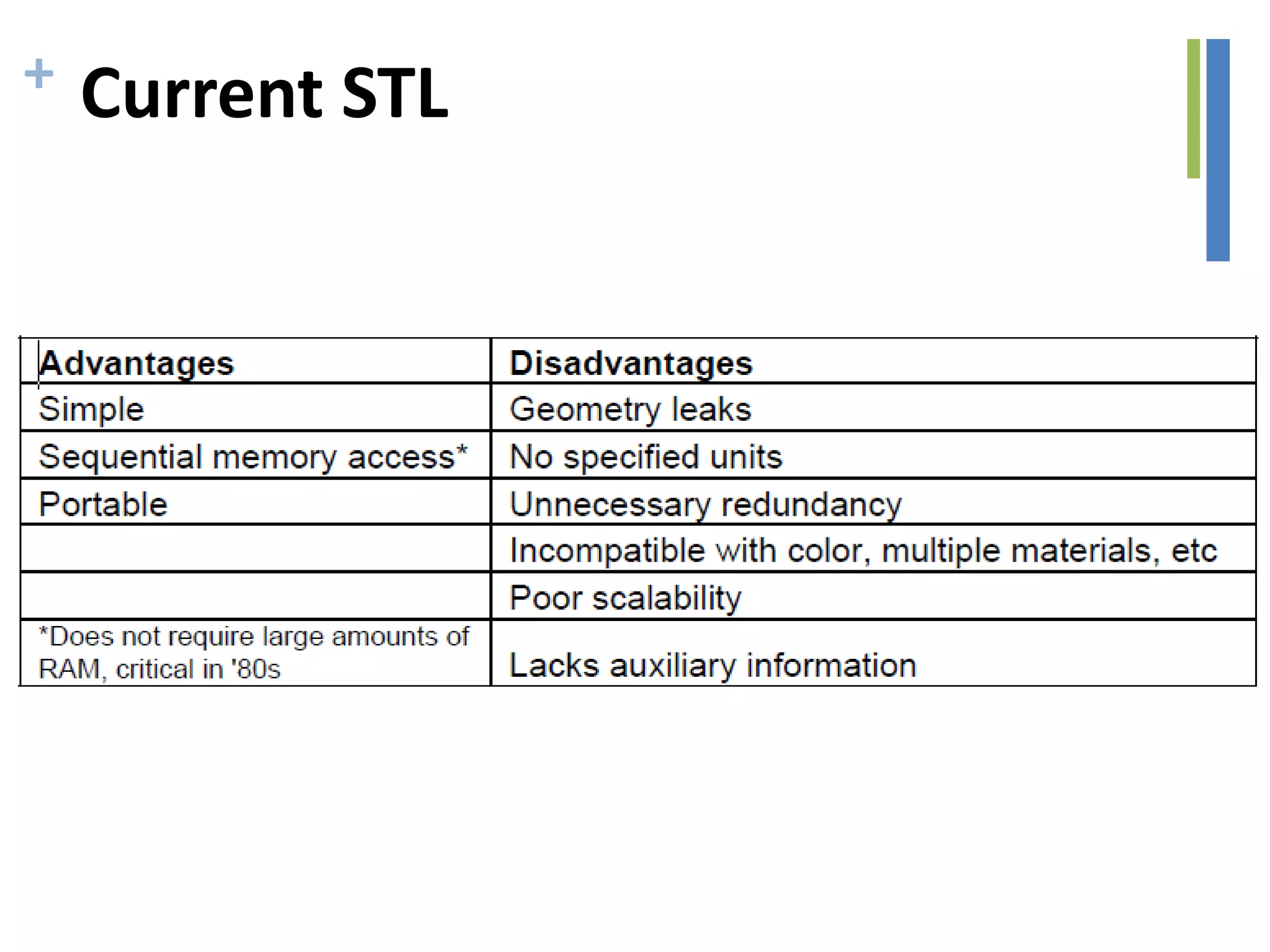
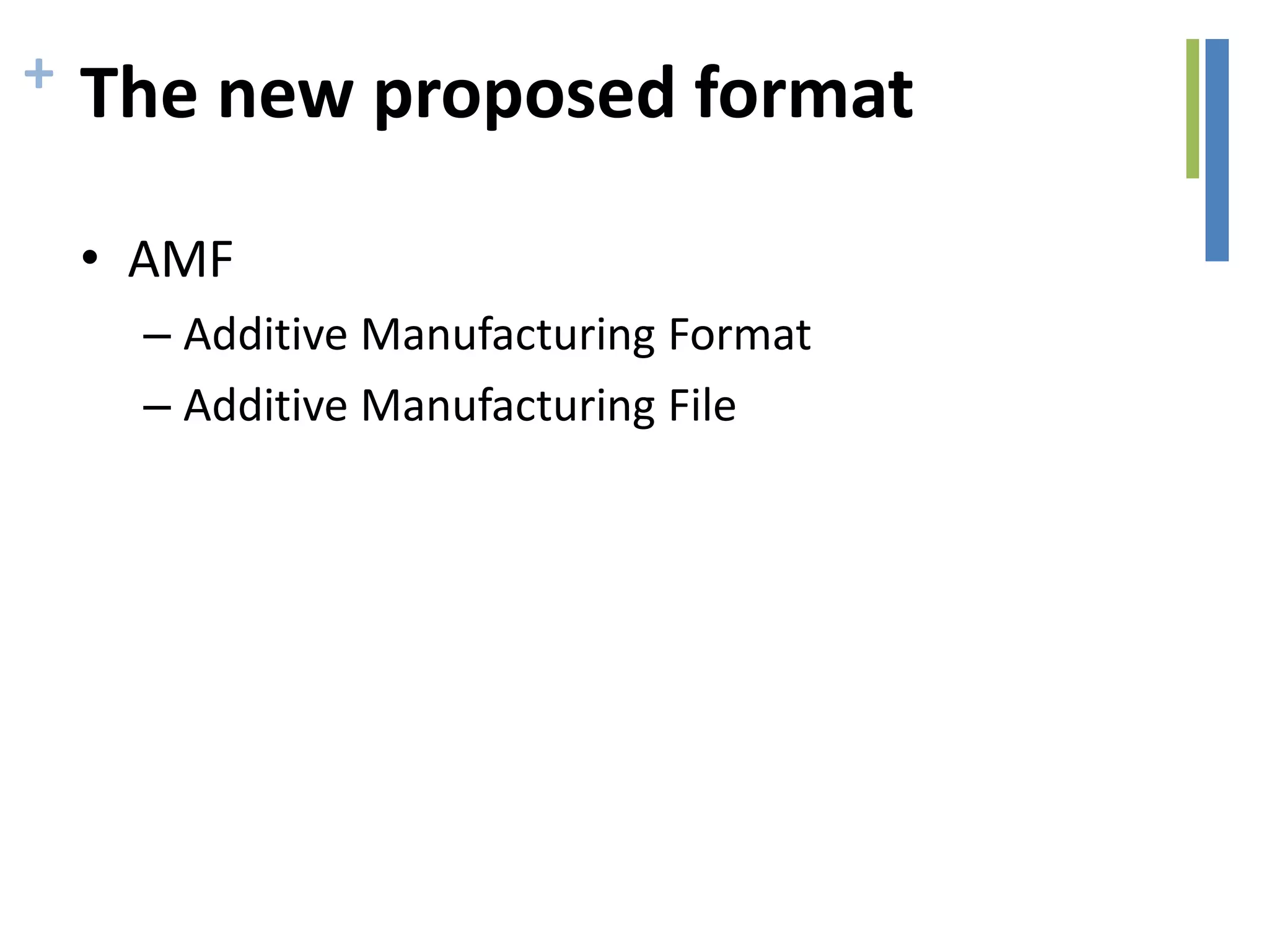
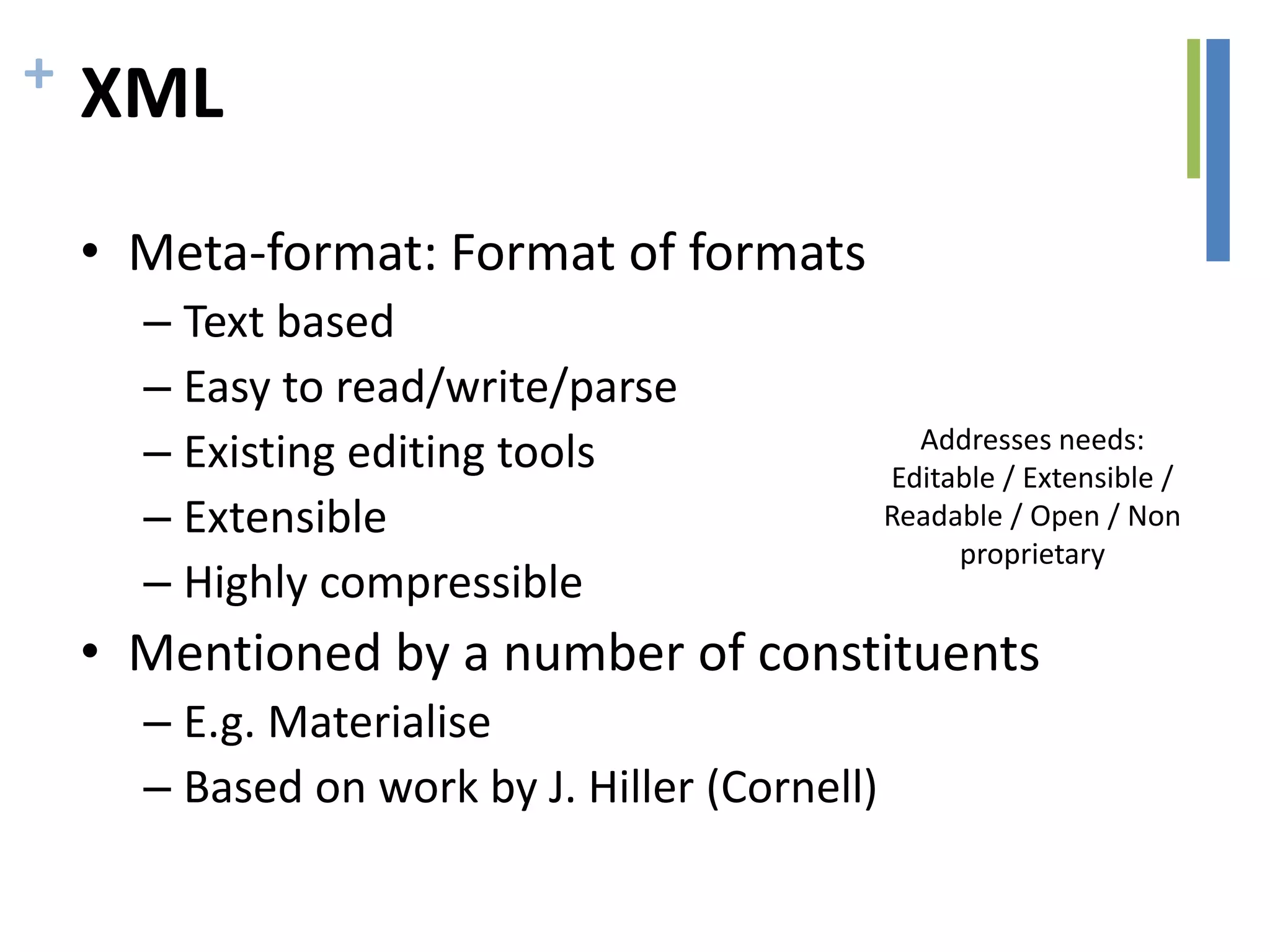
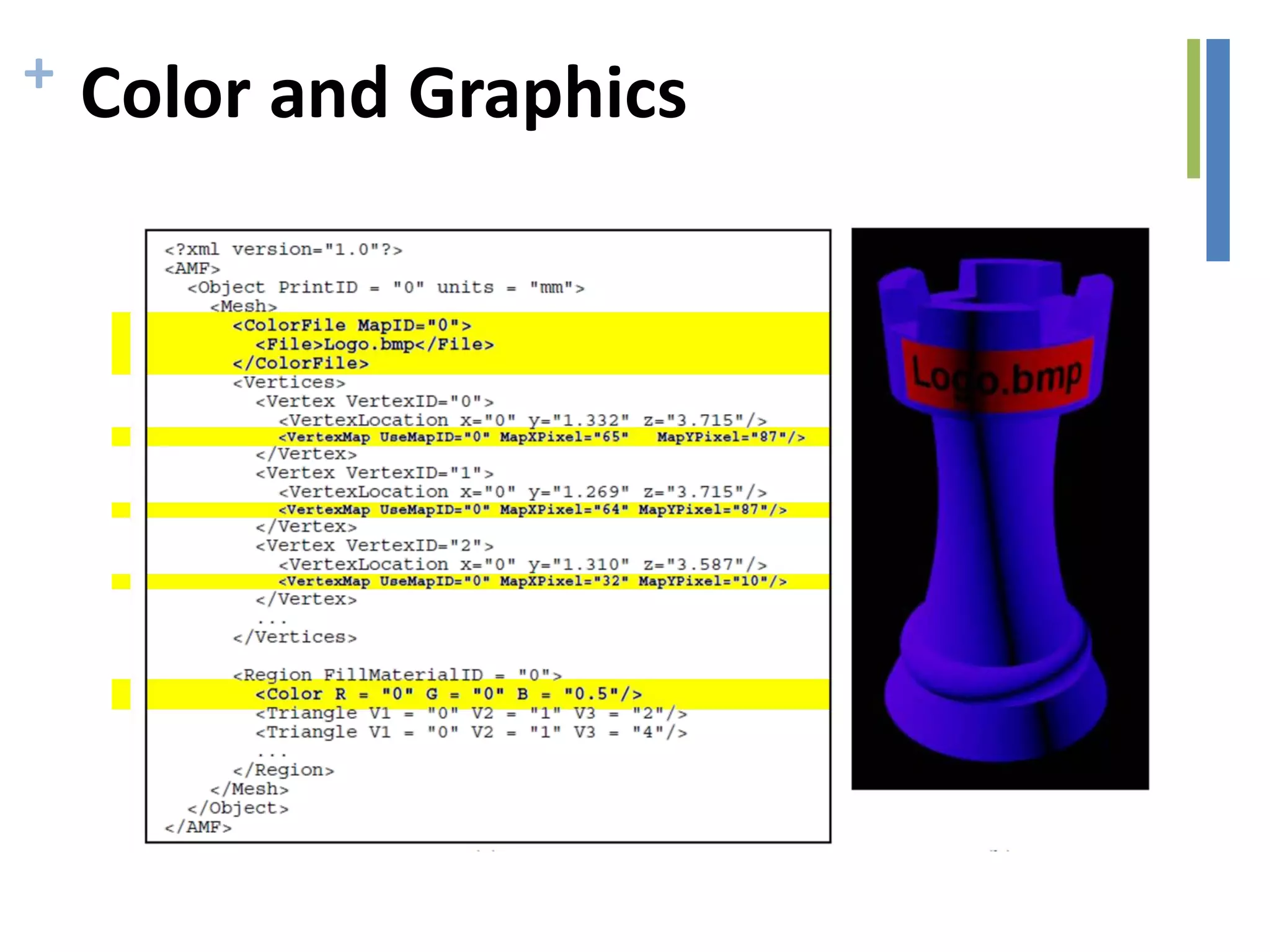
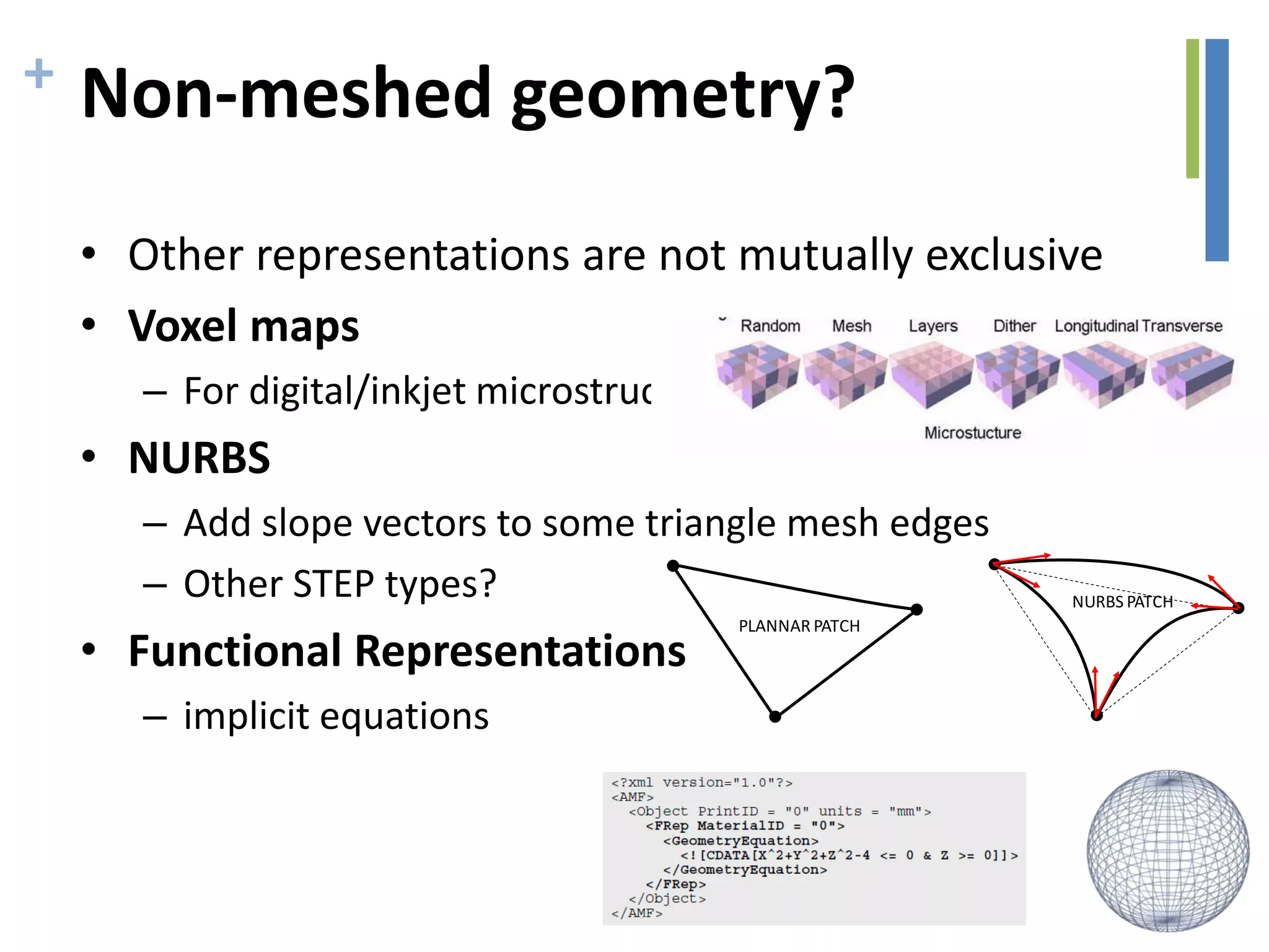
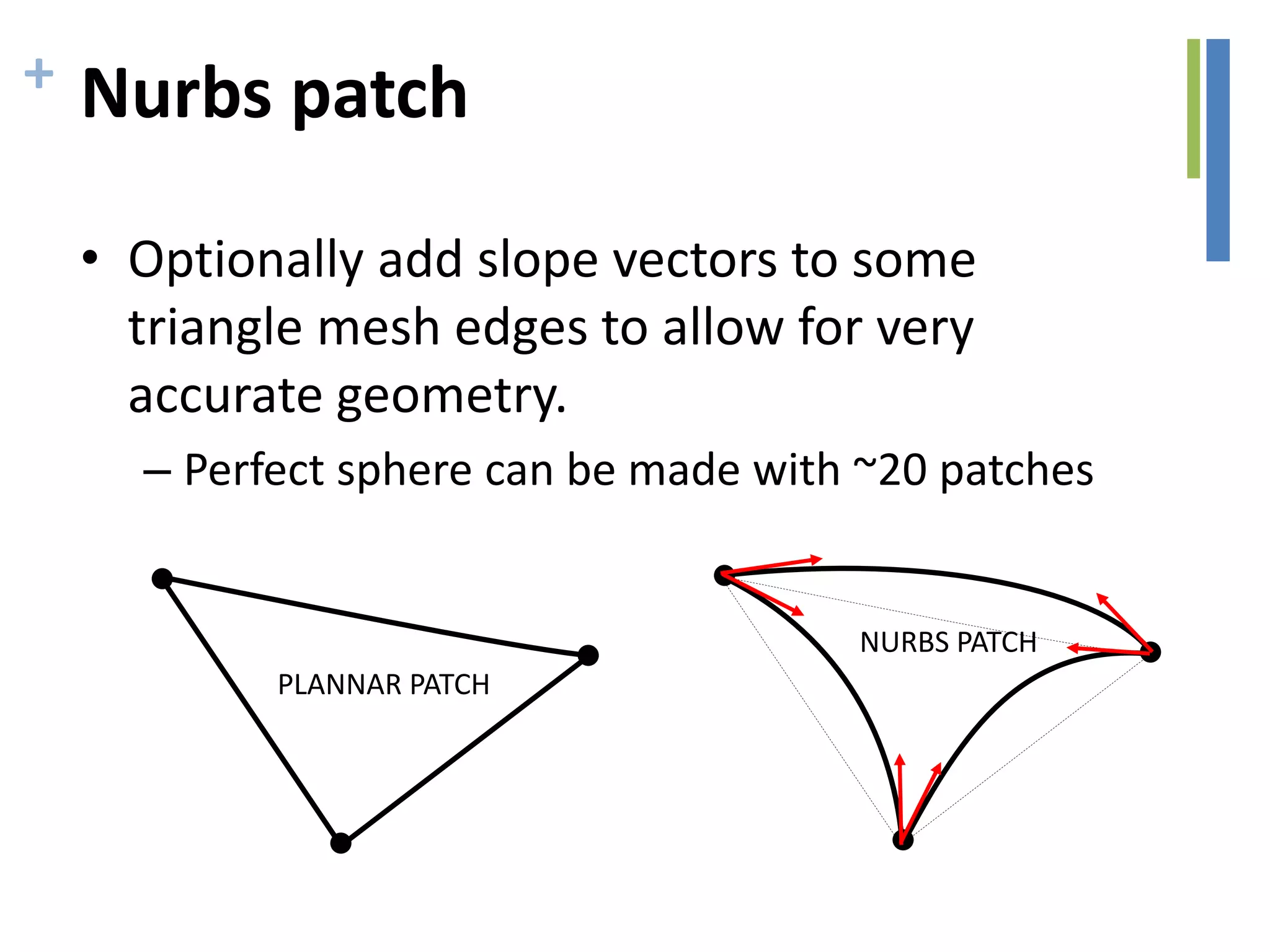
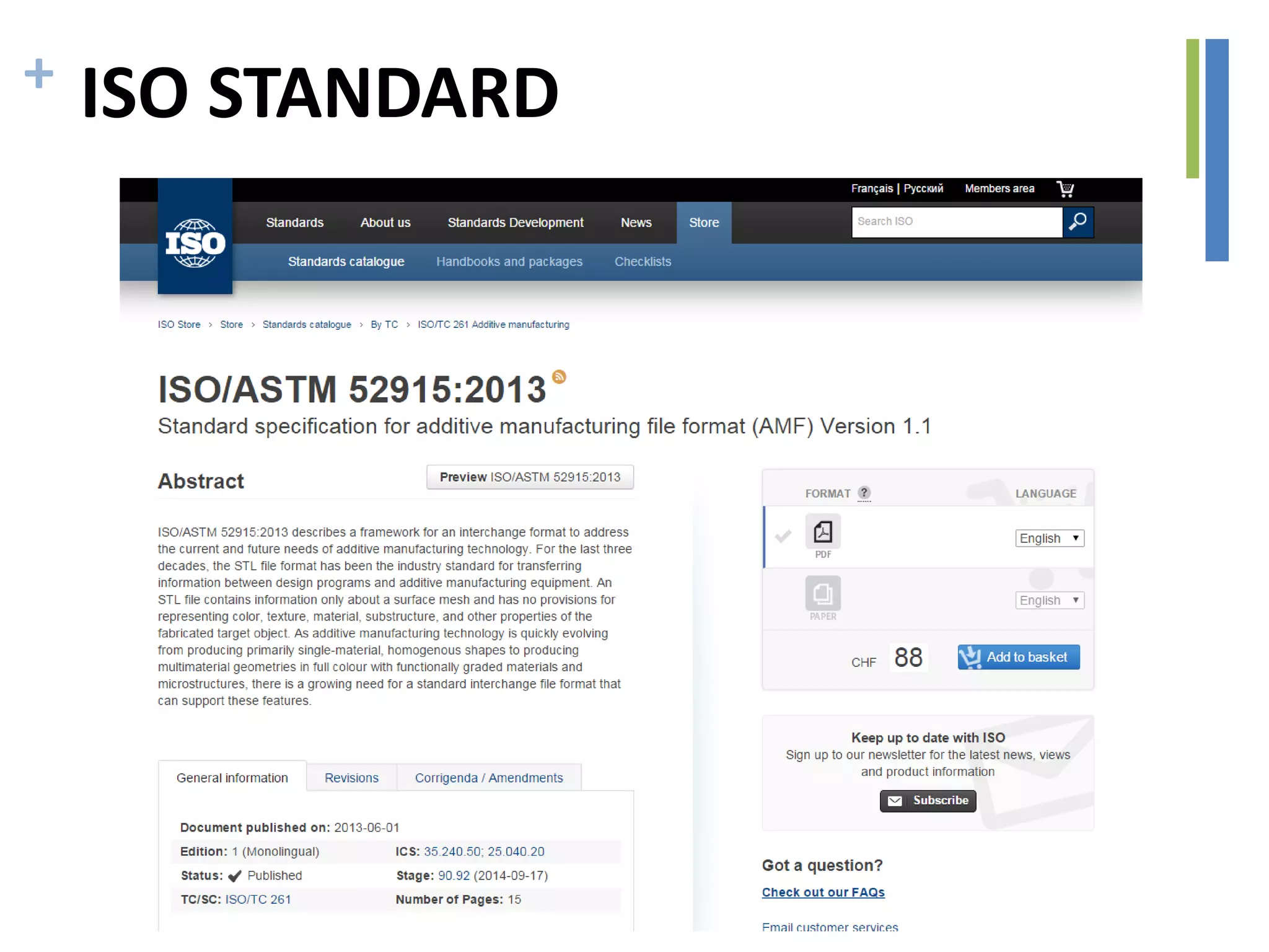

The document discusses the advancements in additive manufacturing and its applications in medical fields such as orthodontics and tissue engineering. It outlines the process flow for additive manufacturing, including software used for CAD modeling, STL file generation, and image analysis for biofabrication. Additionally, it highlights the need for new file formats tailored to the additive manufacturing community to improve interoperability and functionality.