Introduction
Prototype: Itis a model fabricated to prove out a
concept or an idea.
Solid Modelling: It’s a branch of CAD that produces
2D or 3D objects in an electronic format.
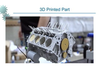
Rapid prototyping is basically a additive
manufacturing process used to quickly fabricate a
model of a part using 3-D CAM data.
It can also be defined as layer by layer fabrication of
3D physical models directly from CAD.
3.
Need for RapidPrototyping
To increase effective communication.
To decrease development time.
To decrease costly mistakes.
To minimise sustaining engineering changes.
To extend product life time by adding necessary
features & eliminating redundant features early in
the design.
4.
Trends in manufacturingindustries
emphasis the following
Increasing the no of variants of products.
Increase in product complexity.
Decrease in product lifetime before obsolescence.
Decrease in delivery time.
Product development by Rapid prototyping by
enabling better communication.
5.
Conventional Machining
Itsnot suitable for complex shapes because they are
difficult to machine.
Time consuming
Very costly
Tedious or very laborious.
Skilled operator is required.
Accuracy will be less.
Increased product development time.
6.
Pre-processing:- CADmodel slicing & setting algorithms
applied for various RP systems.
Post-processing:-Cleaning operations required to finish a
part after removing it from RP machine.
Materials for Rapid Prototyping: Paper, Wax, Plastics,
Resins, Metallic powders.
7.
History of RapidPrototyping
It started in 1980’s
First technique is Stereolithography (SLA)
It was developed by 3D systems of Valencia in California, USA in
1986.
Fused deposition modelling (FDM) developed by stratasys company
in 1988.
Laminated object manufacturing (LOM) developed by Helisis (USA).
Solid ground Curing developed by Cubitol corporation of Israel.
Selective laser sintering developed by DTM of Austin, Texas (USA)
in 1989.
Sanders Model maker developed by Wilton incorporation USA in
1990.
Multi Jet Modelling by 3D systems.
3-D Printing by Solygen incorporation, MIT, USA.
8.
Rapid Prototyping and
Tooling
Inthe development of a new product, there is a need to produce a
single prototype, of a designed part or system before allocating large
amounts of capital to new production facilities or assembly lines.
Consequently, a working prototype is needed for design evaluation
and troubleshooting before a complex product or system is ready to be
produced and marketed.
The traditional method of fabricating a prototype part is machining,
which can require significant lead times.
A virtual prototype, which is a computer model of the part design on a
CAD system, may not be adequate for the designer to visualize the
part.
It certainly is not sufficient to conduct real physical tests on the part,
although it is possible to perform simulated tests by finite element
analysis or other methods.
9.
Advantages of RPT
Rapidprototyping serves as an important tool for visualization and for concept
verification.
With suitable materials, the prototype can be used in subsequent manufacturing
operations to produce the final parts. Sometimes called direct prototyping, this approach
can serve as an important manufacturing technology.
Rapid-prototyping operations can be used in some applications to produce actual tooling
for manufacturing operations. Thus, one can obtain tooling in a matter of a few days.
10.
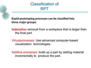
Rapid-prototyping processes canbe classified into
three major groups:
Subtractive: removal from a workpiece that is larger than
the final part.
Virtualprocesses: Use advanced computer-based
visualization technologies.
Additive processes: build up a part by adding material
incrementally to produce the part.
Classification of
RPT
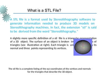
What is aSTL File?
A STL file is a format used by Stereolithography software to
generate information needed to produce 3D models on
Stereolithography machines. In fact, the extension "stl" is said
to be derived from the word "Stereolithography."
A slightly more specific definition of a stl file is a triangular representation
of a 3D object. The surface of an object is broken into a logical series of
triangles (see illustration at right). Each triangle is uniquely defined by its
normal and three points representing its vertices.
The stl file is a complete listing of the xyz coordinates of the vertices and normals
for the triangles that describe the 3D object.
14.
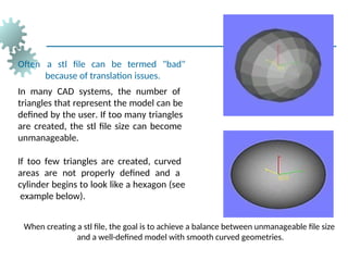
Often a stlfile can be termed "bad"
because of translation issues.
In many CAD systems, the number of
triangles that represent the model can be
defined by the user. If too many triangles
are created, the stl file size can become
unmanageable.
If too few triangles are created, curved
areas are not properly defined and a
cylinder begins to look like a hexagon (see
example below).
When creating a stl file, the goal is to achieve a balance between unmanageable file size
and a well-defined model with smooth curved geometries.
15.
How to createa STL file?
Most CAD software packages offer stl conversion add-ins.
If we have access to conversion software, stl translation is relatively
simple as long as you have a clean-surfaced 3D model and a high-end
computer.
Traditionally when converting to a stl file, the user is given several
options for resolution (sometimes called chord height, triangle
tolerance, etc.). Depending upon the size of the model, the geometry
of small details, and the overall curvature of the part, the tolerance can
typically be set to .001 inch for average models.
Small parts or models with fine details may require a tighter
tolerance.
16.
RP Applications
Applicationsof rapid prototyping can be classified
into three categories:
1. Design
2. Engineering analysis and planning
3. Tooling and manufacturing
17.
Problems with RapidPrototyping
Part accuracy:
Staircase appearance for a sloping part surface
due to layering
Shrinkage and distortion of RP parts
Limited variety of materials in RP
Mechanical performance of the fabricated parts is
limited by the materials that must be used in the
RP process