Downloaded 165 times


![MATERIAL PROPERTIES
• Ultimaker uses 3mm PLA
PLA filament Polymer
• Biodegradable Physical property
thermoplastic Specific Gravity [g/cm3] 1,25
Melt Index [g/10min]
• Highly anisotropic (190º/2,16kg)
4-8
mechanical properties
• Several colors available
5](https://image.slidesharecdn.com/designforultimakerrev2-130304144052-phpapp01/85/Design-for-ultimaker-rev2-5-320.jpg)


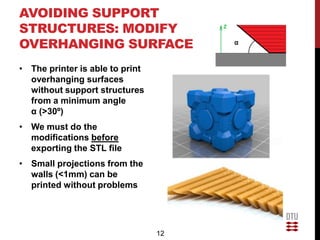
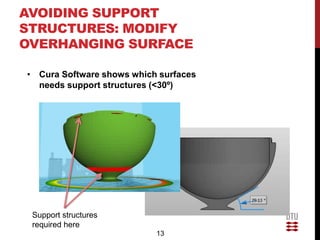
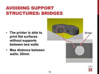
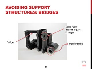

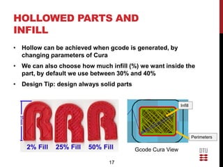


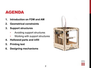
This document provides guidelines for designing parts to be 3D printed on an Ultimaker FDM printer. Key points covered include geometric constraints like minimum wall thicknesses and accuracy tolerances, using support structures effectively by modifying part orientation and features, hollowing parts and optimizing infill, printing clear text, and designing mechanisms with proper clearances between moving parts. The document outlines strategies for preparing CAD models and generating Gcode files to produce high quality 3D prints.


