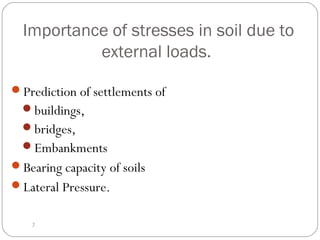
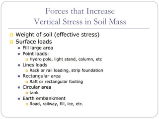
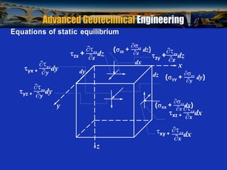
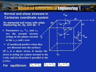
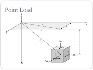
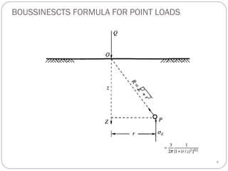
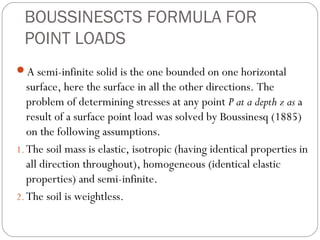
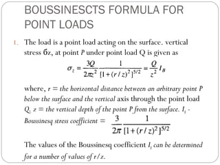
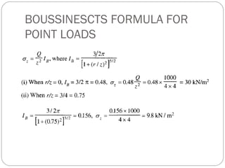
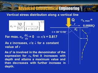
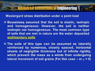
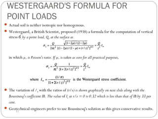
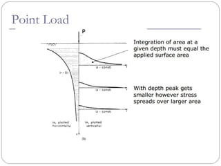
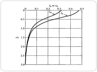
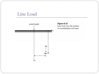
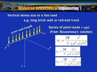
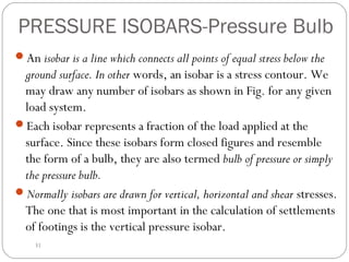
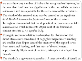
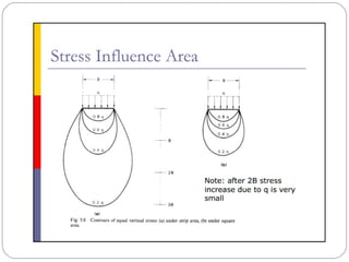
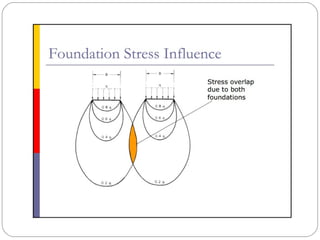
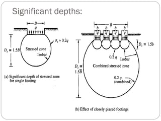
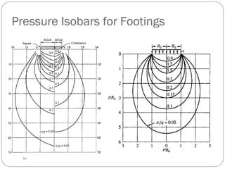
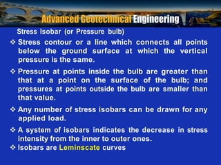
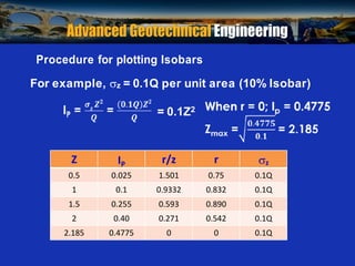
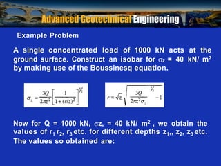
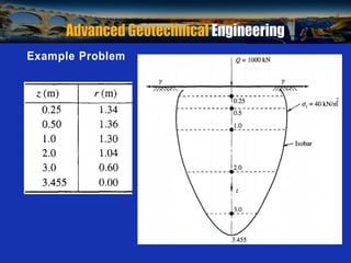
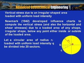
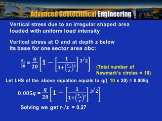
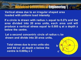
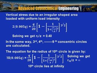
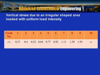
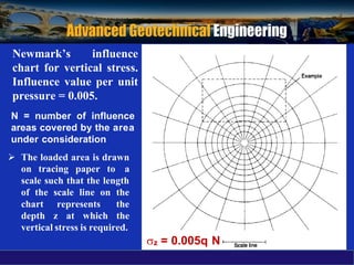
1. Importance of stresses in soil due to
external loads.
Prediction of settlements of
buildings,
bridges,
Embankments
Bearing capacity of soils
Lateral Pressure.
2
2.
3. Prof. B V S Viswanadham, Department of Civil Engineering, IIT Bombay
dx
dy
y
xy +
x
z
Equations of static equilibrium
dz
4. Prof. B V S Viswanadham, Department of Civil Engineering, IIT Bombay
Normal and shear stresses in
Cartesian coordinate system
An elemental soil mass with sides dy
measuring dx, dy, and dz:
zx
zz
dx
x
zy
dz
Parameters xx
yy, and zz
yx
yy
are the normal stresses
acting on the planes normal y
to the x, y, and z axes
yz
xy
xz
xx
(Considered positive when they
are directed onto the surface)
(If ij is a shear stress, it means the
stress is acting on a plane normal to the z
i axis, and its direction is parallel to the
j axis.)
For equilibrium:
7. BOUSSINESCTS FORMULA FOR
POINT LOADS
A semi-infinite solid is the one bounded on one horizontal
surface, here the surface in all the other directions. The
problem of determining stresses at any point P at a depth z as a
result of a surface point load was solved by Boussinesq (1885)
on the following assumptions.
1. The soil mass is elastic, isotropic (having identical properties in
all direction throughout), homogeneous (identical elastic
properties) and semi-infinite.
2. The soil is weightless.
8. BOUSSINESCTS FORMULA FOR
POINT LOADS
1. The load is a point load acting on the surface. vertical
stress бz, at point P under point load Q is given as
where, r = the horizontal distance between an arbitrary point P
below the surface and the vertical axis through the point load
Q. z = the vertical depth of the point P from the surface. IB -
Boussinesq stress coefficient =
The values of the Boussinesq coefficient IB can be determined
for a number of values of r/z.
10. Prof. B V S Viswanadham, Department of Civil Engineering, IIT Bombay
Vertical stress distribution along a vertical line
Q z, max =
r
z
= 391350
0.0888Q
As z increases, r/z for a constant
value of r
As z2 is involved in the denominator of the
expression for z, first it increases with
depth and attains a maximum value and
then decreases with further increase in
depth.
11. Prof. B V S Viswanadham, Department of Civil Engineering, IIT Bombay
Westergard stress distribution under a point load
Boussinesq assumed that the soil is elastic, isotropic
and homogeneous; However, the soil is neither
isotropic nor homogeneous. The most common type
of soils that are met in nature are the water deposited
sedimentary soils
The soils of this type can be assumed as laterally
reinforced by numerous, closely spaced, horizontal
sheets of negligible thickness but of infinite rigidity,
which prevent the mass as a whole from undergoing
lateral movement of soil grains (For this case or = 0)
12. WESTERGAARD'S FORMULA FOR
POINT LOADS
Actual soil is neither isotropic nor homogenous.
Westergaard, a British Scientist, proposed (1938) a formula for the computation of vertical
stress бz by a point load, Q, at the surface as
in which µ, is Poisson's ratio. If µ, is taken as zero for all practical purposes,
The variation of /B with the ratios of (r/z) is shown graphically on next slide along with the
Boussinesq's coefficient IB. The value of Iw at r/z = 0 is 0.32 which is less than that of IB by 33 per
cent.
Geotechnical engineers prefer to use Boussinesq's solution as this gives conservative results.
12
13.
14.
15.
16. Prof. B V S Viswanadham, Department of Civil Engineering, IIT Bombay
Vertical stress due to a line load
e.g, long brick wall or railroad track
Series of point loads (~qdy)
- (From Boussinesq’s solution)
y x
z
17.
18.
19.
20.
21.
22.
23.
24.
25.
26.
27.
28.
29.
30.
31.
32. PRESSURE ISOBARS-Pressure Bulb
An isobar is a line which connects all points of equal stress below the
ground surface. In other words, an isobar is a stress contour. We
may draw any number of isobars as shown in Fig. for any given
load system.
Each isobar represents a fraction of the load applied at the
surface. Since these isobars form closed figures and resemble
the form of a bulb, they are also termed bulb of pressure or simply
the pressure bulb.
Normally isobars are drawn for vertical, horizontal and shear stresses.
The one that is most important in the calculation of settlements
of footings is the vertical pressure isobar.
31
33. we may draw any number of isobars for any given load system, but
the one that is of practical significance is the one which encloses a
soil mass which is responsible for the settlement of the structure.
The depth of this stressed zone may be termed as the significant
depth Ds which is responsible for the settlement of the structure.
Terzaghi recommended that for all practical purposes one can take
a stress contour which represents 20 per cent of the foundation
contact pressure q, i.e, equal to 0.2q.
Terzaghi's recommendation was based on his observation that
direct stresses are considered of negligible magnitude when they
are smaller than 20 per cent of the intensity of the applied stress
from structural loading, and that most of the settlement,
approximately 80 per cent of the total, takes place at a depth less
than Ds.
The depth Ds is approximately equal to 1.5 times the width of square or
32
38. Prof. B V S Viswanadham, Department of Civil Engineering, IIT Bombay
Stress Isobar (or Pressure bulb)
Stress contour or a line which connects all points
below the ground surface at which the vertical
pressure is the same.
Pressure at points inside the bulb are greater than
that at a point on the surface of the bulb; and
pressures at points outside the bulb are smaller than
that value.
Any number of stress isobars can be drawn for any
applied load.
A system of isobars indicates the decrease in stress
intensity from the inner to outer ones.
Isobars are Leminscate curves
39. Prof. B V S Viswanadham, Department of Civil Engineering, IIT Bombay
= 0.1Z2
Procedure for plotting Isobars
For example, z = 0.1Q per unit area (10% Isobar)
Z IP r/z r z
0.5 0.025 1.501 0.75 0.1Q
1 0.1 0.9332 0.832 0.1Q
1.5 0.255 0.593 0.890 0.1Q
2 0.40 0.271 0.542 0.1Q
2.185 0.4775 0 0 0.1Q
40. Prof. B V S Viswanadham, Department of Civil Engineering, IIT Bombay
Example Problem
A single concentrated load of 1000 kN acts at the
ground surface. Construct an isobar for z = 40 kN/ m2
by making use of the Boussinesq equation.
Now for Q = 1000 kN, z, = 40 kN/ m2 , we obtain the
values of r1 r2, r3 etc. for different depths z1,, z2, z3 etc.
The values so obtained are:
41. Prof. B V S Viswanadham, Department of Civil Engineering, IIT Bombay
Example Problem
42. Prof. B V S Viswanadham, Department of Civil Engineering, IIT Bombay
r1
o
c
Vertical stress due to an irregular shaped area
loaded with uniform load intensity
Newmark (1942) developed influence charts to
compute the vertical stress (and also the horizontal and
shear stresses) due to a loaded area of any shape,
irregular shape, below any point either inside or outside
of the loaded area.
Let a circular area of radius r1
loaded with uniform load intensity q
b
be divided into 20 sectors.
43. Prof. B V S Viswanadham, Department of Civil Engineering, IIT Bombay
Vertical stress due to an irregular shaped area
loaded with uniform load intensity
Vertical stress at O and at depth z below
its base for one sector area obc:
(Total number of
Newmark’s circles = 10)
Let LHS of the above equation equals to q/( 10 x 20) = 0.005q
Solving we get r1 /z = 0.27
44. Vertical stress due to an irregular shaped area
loaded with uniform load intensity
If a circle is drawn with radius r1 equal to 0.27z and the
area divided into 20 area units, each area unit will
produce a vertical stress equal to 0.005 q at a depth z
below the centre.
Let a second concentric circle of radius r2 be
drawn and divide into 20 area units,
Total stress due to area units obc
and bbcc at depth z below the
centre is 0.005q x 2
r2
b b o
c
c
r1
45. Prof. B V S Viswanadham, Department of Civil Engineering, IIT Bombay
Vertical stress due to an irregular shaped area
loaded with uniform load intensity
Solving we get r2 /z = 0.40
In the same way, 3rd, 4th, -------9 th concentric circles
are calculated.
The equation for the radius of 10th circle is given by:
Solving we get
r10 /z =
10th circle lies at infinity
46. Prof. B V S Viswanadham, Department of Civil Engineering, IIT Bombay
Vertical stress due to an irregular shaped area
loaded with uniform load intensity
Circle
No.
1 2 3 4 5 6 7 8 9 10
r/z 0.27 0.4 0.52 0.64 0.77 0.92 1.11 1.39 1.91
47. Newmark’s influence
chart for vertical stress.
Influence value per unit
pressure = 0.005.
N = number of influence
areas covered by the area
under consideration
The loaded area is drawn
on tracing paper to a
scale such that the length
of the scale line on the
chart represents the
depth z at which the
vertical stress is required.
z = 0.005q N