Downloaded 208 times
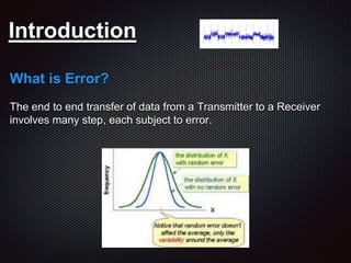
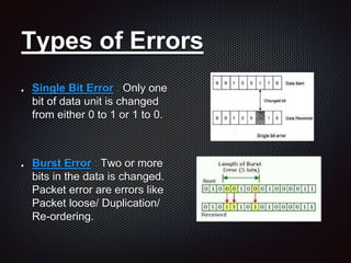

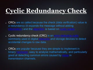

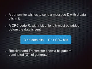


This document discusses error detection techniques including cyclic redundancy checks (CRCs) and discusses the differences between bit rate errors and frame rate errors. It can be summarized as: 1. CRCs are a commonly used error detection technique where a check value is calculated based on the data and transmitted with it to allow the receiver to check for errors. 2. Bit rate error refers to the rate of errors in transmitted bits, while frame rate error refers to the ratio of data received with errors to the total data received. 3. A method is presented for estimating both bit error rate and frame error rate for low-density parity-check codes based on enumerating the smallest weight error patterns that cannot be corrected.