![Equations 45
FS = Flat Span Dimension (Inches)
MAJOR = Major Axis Dimension [Inches (Larger Dimension)]
MINOR = Minor Axis Dimension [Inches (Smaller Dimension)]
A = Cross-Sectional Area (Square Feet)
P = Perimeter or Surface Area (Square Feet per Lineal Feet)
DEQ = Equivalent Round Duct Diameter
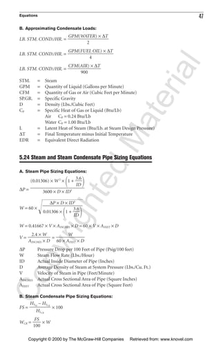
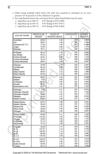
5.22 Pipe Expansion Equations
A. L-Bends:
L = 6.225 × ͙∆Dෆ
F = 500 LB./PIPE DIA. × PIPE DIA.
L = Length of Leg Required to Accommodate Thermal Expansion or Contraction
(Feet)
∆ = Thermal Expansion or Contraction of Long Leg (Inches)
D = Pipe Outside Diameter (Inches)
F = Force Exerted by Pipe Expansion or Contraction on Anchors and Supports (Lbs.)
See Tables in Part 32, Appendix D
B. Z-Bends:
L = 4 × ͙∆Dෆ
F = 200 − 500 LB./PIPE DIA. × PIPE DIA.
CopyrightedMaterial
Copyright © 2000 by The McGraw-Hill Companies Retrieved from: www.knovel.com](https://image.slidesharecdn.com/equations-180517180232/85/Equations-11-320.jpg)
![50 PART 5
HOUTPUT = Heating Capacity, Output
HINPUT = Heating Capacity, Input
GPH = Recovery Rate (Gallons per Hour)
∆T = Temperature Rise (°F.)
KW = Kilowatts
TCOLD = Temperature, Cold Water (°F.)
THOT = Temperature, Hot Water (°F.)
TMIX = Temperature, Mixed Water (°F.)
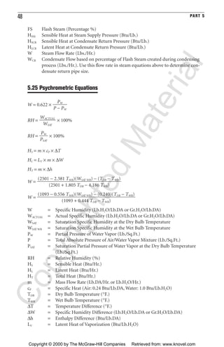
5.28 Domestic Hot Water Recirculation Pump/Supply Sizing
A. Determine the approximate total length of all hot water supply and return piping.
B. Multiply this total length by 30 Btu/Ft. for insulated pipe and 60 Btu/Ft. for unin-
sulated pipe to obtain the approximate heat loss.
C. Divide the total heat loss by 10,000 to obtain the total pump capacity in GPM.
D. Select a circulating pump to provide the total required GPM and obtain the head
created at this flow.
E. Multiply the head by 100 and divide by the total length of the longest run of the
hot water return piping to determine the allowable friction loss per 100 feet of pipe.
F. Determine the required GPM in each circulating loop and size the hot water
return pipe based on this GPM and the allowable friction loss as determined above.
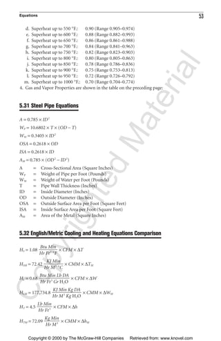
5.29 Relief Valve Vent Line Maximum Length
L = =
P1 = 0.25 × [(PRESSURE SETTING × 1.1) + 14.7]
P2 = [(PRESSURE SETTING × 1.1) + 14.7]
L = Maximum Length of Relief Vent Line (Feet)
D = Inside Diameter of Pipe (Inches)
C = Minimum Discharge of Air (Lbs./Min.)
5.30 Relief Valve Sizing
A. Liquid System Relief Valves and Spring Style Relief Valves:
A =
B. Liquid System Relief Valves and Pilot Operated Relief Valves:
A =
GPM × ͙Gෆ
ᎏᎏ
36.81 × KV × ͙∆Pෆ
GPM × ͙Gෆ
ᎏᎏᎏ
28.14 × KB × KV × ͙∆Pෆ
9 × P2
2
× D5
ᎏᎏ
16 × C2
9 × P1
2
× D5
ᎏᎏ
C2
CopyrightedMaterial
Copyright © 2000 by The McGraw-Hill Companies Retrieved from: www.knovel.com](https://image.slidesharecdn.com/equations-180517180232/85/Equations-16-320.jpg)
![Equations 55
1.0 GPM = 500 Lb. Steam/Hr.
1.0 Lb.Stm. /Hr = 0.002 GPM
1.0 Lb.H2O/Hr = 1.0 Lb.Steam/Hr.
Kg/Cu. Meter = Pounds/Cu. Feet × 16.017 (Density)
Cu. Meters/Kg = Cu. Feet/Pound × 0.0624 (Specific Volume)
Kg H2O/Kg DA = Gr H2O/Lb DA/7,000 = Lb. H2O/Lb DA
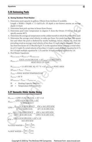
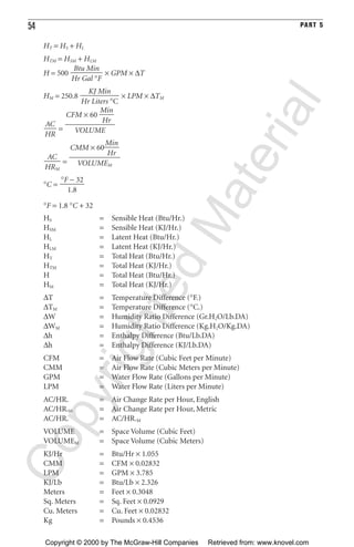
5.33 Cooling Tower Equations
C =
B =
E = GPMCOND. × R × 0.0008
D = GPMCOND. × 0.0002
R = EWT − LWT
B = Blowdown (GPM)
C = Cycles of Concentration
D = Drift (GPM)
E = Evaporation (GPM)
EWT = Entering Water Temperature (°F.)
LWT = Leaving Water Temperature (°F.)
R = Range (°F.)
5.34 Motor Drive Formulas
DFP × RPMFP = DMP × RPMMP
BL = [(DFP + DMP) × 1.5708] + (2 × L)
DFP = Fan Pulley Diameter
DMP = Motor Pulley Diameter
RPMFP = Fan Pulley RPM
RPMMP = Motor Pulley RPM
BL = Belt Length
L = Center-to-Center Distance of Fan and Motor Pulleys
E − [(C − 1) × D]
ᎏᎏ
(C − 1)
(E + D + B)
ᎏᎏ
(D + B)
CopyrightedMaterial
Copyright © 2000 by The McGraw-Hill Companies Retrieved from: www.knovel.com](https://image.slidesharecdn.com/equations-180517180232/85/Equations-21-320.jpg)

This document contains equations and rules of thumb for HVAC systems. It includes equations for cooling and heating load calculations, ductwork sizing, fan and pump laws, expansion tank sizing, air balancing, efficiencies, cooling towers, moisture condensation, and electricity. The equations are presented along with brief explanations of the variables.