SlideShare a Scribd company logo
‫شرح‬‫مروحة‬‫الدخان‬
Mechanical Smoke Ventilation Calculations
For Basement Floor ( Store)
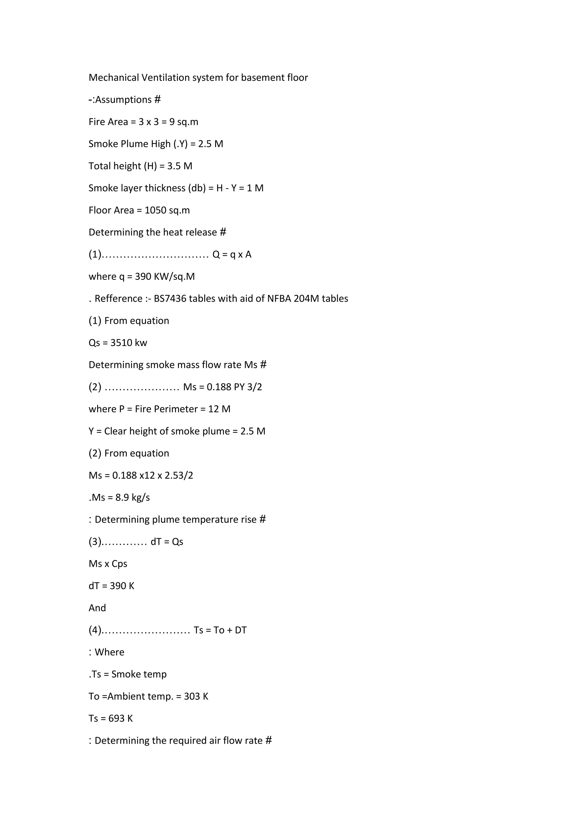
Mechanical Ventilation system for basement floor
#Assumptions:-
Fire Area = 3 x 3 = 9 sq.m
Smoke Plume High (.Y) = 2.5 M
Total height (H) = 3.5 M
Smoke layer thickness (db) = H - Y = 1 M
Floor Area = 1050 sq.m
#Determining the heat release
Q = q x A…………………………(1)
where q = 390 KW/sq.M
Refference :- BS7436 tables with aid of NFBA 204M tables.
From equation(1)
Qs = 3510 kw
#Determining smoke mass flow rate Ms
Ms = 0.188 PY 3/2…………………(2)
where P = Fire Perimeter = 12 M
Y = Clear height of smoke plume = 2.5 M
From equation(2)
Ms = 0.188 x12 x 2.53/2
Ms = 8.9 kg/s.
#Determining plume temperature rise:
dT = Qs…………(.3)
Ms x Cps
dT = 390 K
And
Ts = To + DT……………………(.4)
Where:
Ts = Smoke temp.
To =Ambient temp. = 303 K
Ts = 693 K
#Determining the required air flow rate:
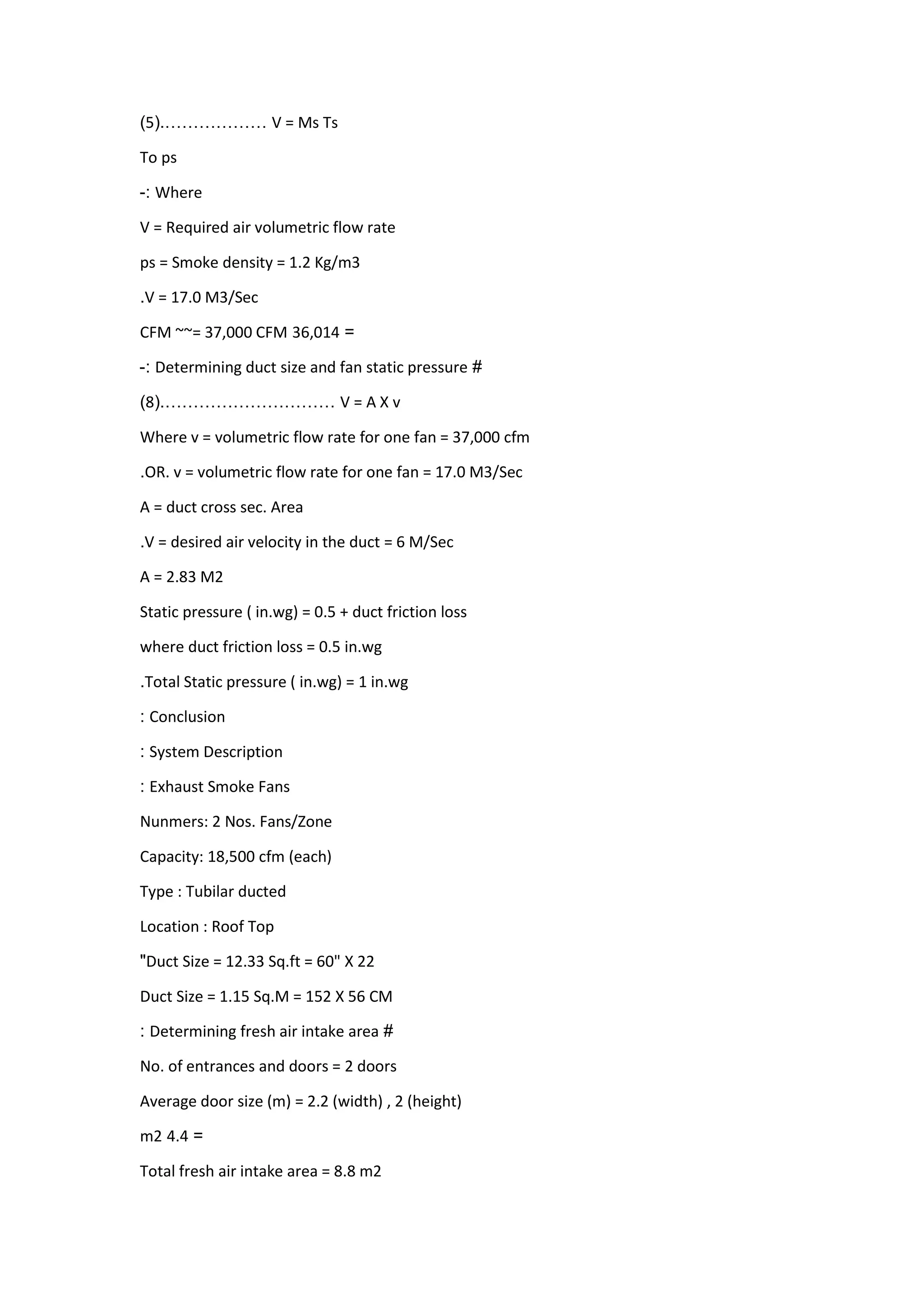
V = Ms Ts………………(.5)
To ps
Where:-
V = Required air volumetric flow rate
ps = Smoke density = 1.2 Kg/m3
V = 17.0 M3/Sec.
=310,14CFM ~~= 37,000 CFM
#Determining duct size and fan static pressure:-
V = A X v…………………………(.8)
Where v = volumetric flow rate for one fan = 37,000 cfm
OR. v = volumetric flow rate for one fan = 17.0 M3/Sec.
A = duct cross sec. Area
V = desired air velocity in the duct = 6 M/Sec.
A = 2.83 M2
Static pressure ( in.wg) = 0.5 + duct friction loss
where duct friction loss = 0.5 in.wg
Total Static pressure ( in.wg) = 1 in.wg.
Conclusion:
System Description:
Exhaust Smoke Fans:
Nunmers: 2 Nos. Fans/Zone
Capacity: 18,500 cfm (each)
Type : Tubilar ducted
Location : Roof Top
Duct Size = 12.33 Sq.ft = 60" X 22"
Duct Size = 1.15 Sq.M = 152 X 56 CM
#Determining fresh air intake area:
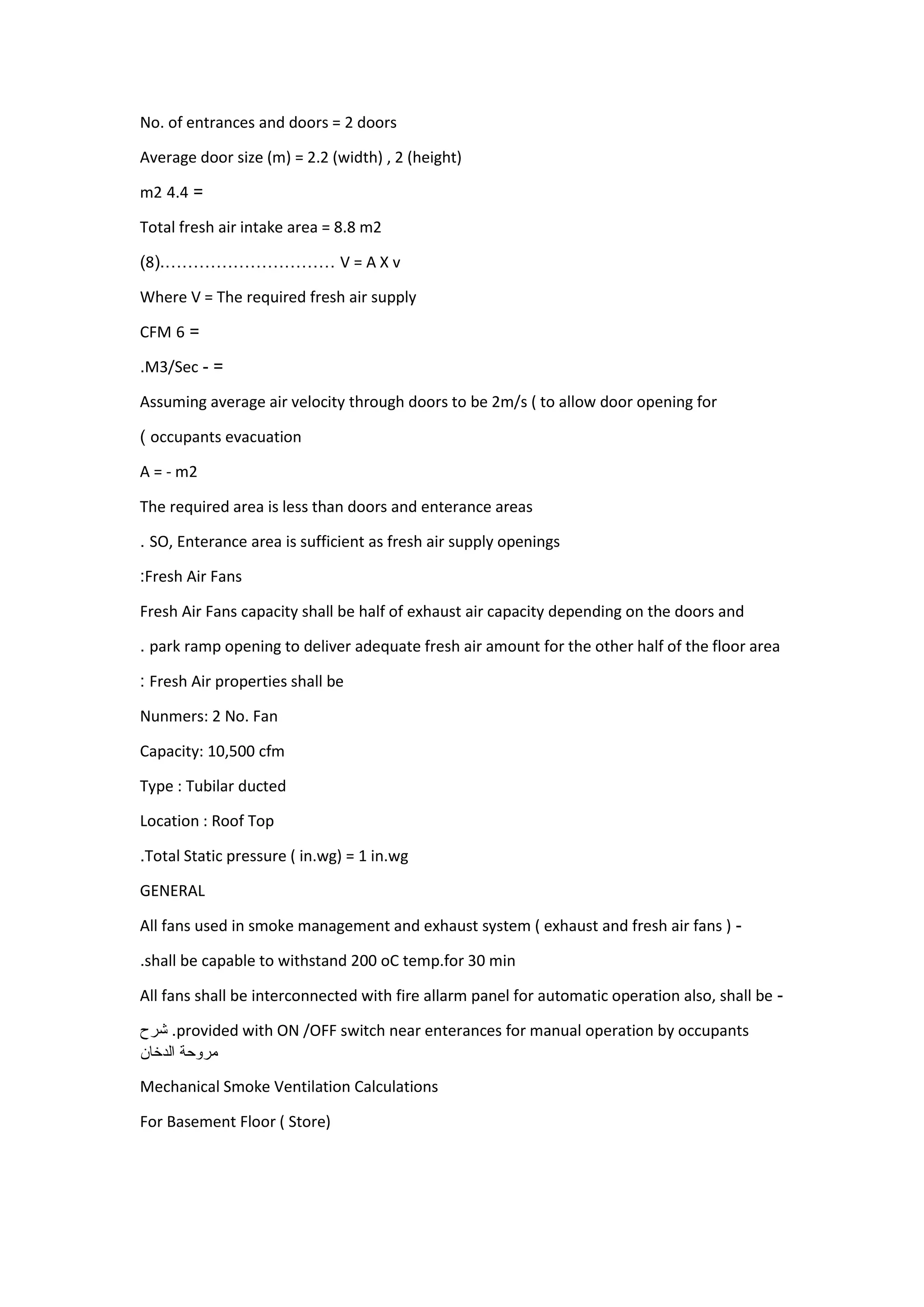
No. of entrances and doors = 2 doors
Average door size (m) = 2.2 (width) , 2 (height)
=4.4m2
Total fresh air intake area = 8.8 m2
V = A X v…………………………(.8)
Where V = The required fresh air supply
=1CFM
=-M3/Sec.
Assuming average air velocity through doors to be 2m/s ( to allow door opening for
occupants evacuation)
A = - m2
The required area is less than doors and enterance areas
SO, Enterance area is sufficient as fresh air supply openings.
Fresh Air Fans:
Fresh Air Fans capacity shall be half of exhaust air capacity depending on the doors and
park ramp opening to deliver adequate fresh air amount for the other half of the floor area.
Fresh Air properties shall be:
Nunmers: 2 No. Fan
Capacity: 10,500 cfm
Type : Tubilar ducted
Location : Roof Top
Total Static pressure ( in.wg) = 1 in.wg.
GENERAL
-All fans used in smoke management and exhaust system ( exhaust and fresh air fans )
shall be capable to withstand 200 oC temp.for 30 min.
-All fans shall be interconnected with fire allarm panel for automatic operation also, shall be
provided with ON /OFF switch near enterances for manual operation by occupants.‫شرح‬
‫مروحة‬‫الدخان‬
Mechanical Smoke Ventilation Calculations
For Basement Floor ( Store)
Mechanical Ventilation system for basement floor
#Assumptions:-
Fire Area = 3 x 3 = 9 sq.m
Smoke Plume High (.Y) = 2.5 M
Total height (H) = 3.5 M
Smoke layer thickness (db) = H - Y = 1 M
Floor Area = 1050 sq.m
#Determining the heat release
Q = q x A…………………………(1)
where q = 390 KW/sq.M
Refference :- BS7436 tables with aid of NFBA 204M tables.
From equation(1)
Qs = 3510 kw
#Determining smoke mass flow rate Ms
Ms = 0.188 PY 3/2…………………(2)
where P = Fire Perimeter = 12 M
Y = Clear height of smoke plume = 2.5 M
From equation(2)
Ms = 0.188 x12 x 2.53/2
Ms = 8.9 kg/s.
#Determining plume temperature rise:
dT = Qs…………(.3)
Ms x Cps
dT = 390 K
And
Ts = To + DT……………………(.4)
Where:
Ts = Smoke temp.
To =Ambient temp. = 303 K
Ts = 693 K
#Determining the required air flow rate:
V = Ms Ts………………(.5)
To ps
Where:-
V = Required air volumetric flow rate
ps = Smoke density = 1.2 Kg/m3
V = 17.0 M3/Sec.
=310,14CFM ~~= 37,000 CFM
#Determining duct size and fan static pressure:-
V = A X v…………………………(.8)
Where v = volumetric flow rate for one fan = 37,000 cfm
OR. v = volumetric flow rate for one fan = 17.0 M3/Sec.
A = duct cross sec. Area
V = desired air velocity in the duct = 6 M/Sec.
A = 2.83 M2
Static pressure ( in.wg) = 0.5 + duct friction loss
where duct friction loss = 0.5 in.wg
Total Static pressure ( in.wg) = 1 in.wg.
Conclusion:
System Description:
Exhaust Smoke Fans:
Nunmers: 2 Nos. Fans/Zone
Capacity: 18,500 cfm (each)
Type : Tubilar ducted
Location : Roof Top
Duct Size = 12.33 Sq.ft = 60" X 22"
Duct Size = 1.15 Sq.M = 152 X 56 CM
#Determining fresh air intake area:
No. of entrances and doors = 2 doors
Average door size (m) = 2.2 (width) , 2 (height)
=4.4m2
Total fresh air intake area = 8.8 m2
V = A X v…………………………(.8)
Where V = The required fresh air supply
=1CFM
=-M3/Sec.
Assuming average air velocity through doors to be 2m/s ( to allow door opening for
occupants evacuation)
A = - m2
The required area is less than doors and enterance areas
SO, Enterance area is sufficient as fresh air supply openings.
Fresh Air Fans:
Fresh Air Fans capacity shall be half of exhaust air capacity depending on the doors and
park ramp opening to deliver adequate fresh air amount for the other half of the floor area.
Fresh Air properties shall be:
Nunmers: 2 No. Fan
Capacity: 10,500 cfm
Type : Tubilar ducted
Location : Roof Top
Total Static pressure ( in.wg) = 1 in.wg.
GENERAL
-All fans used in smoke management and exhaust system ( exhaust and fresh air fans )
shall be capable to withstand 200 oC temp.for 30 min.
-All fans shall be interconnected with fire allarm panel for automatic operation also, shall be
provided with ON /OFF switch near enterances for manual operation by occupants.

More Related Content

What's hot

Introduction to hvac systems
Introduction to hvac systemsIntroduction to hvac systems
Introduction to hvac systems
michaeljmack
 
Smoke extraction in buildings
Smoke extraction in buildingsSmoke extraction in buildings
Smoke extraction in buildings
vysakhmanohar
 
BS2 Hvac ventilation 1
BS2 Hvac ventilation 1BS2 Hvac ventilation 1
BS2 Hvac ventilation 1
Est
 
Hvac formulas
Hvac formulasHvac formulas
Hvac formulas
hvactrg1
 

What's hot (20)

Introduction to hvac systems
Introduction to hvac systemsIntroduction to hvac systems
Introduction to hvac systems
 
Hvac systems presentation_slides
Hvac systems presentation_slidesHvac systems presentation_slides
Hvac systems presentation_slides
 
Project on HVACR
Project on HVACRProject on HVACR
Project on HVACR
 
Hvac chilled water distribution schemes
Hvac chilled water distribution schemesHvac chilled water distribution schemes
Hvac chilled water distribution schemes
 
S3 Lec 6 (Air Distribution) Note
S3 Lec 6 (Air Distribution) NoteS3 Lec 6 (Air Distribution) Note
S3 Lec 6 (Air Distribution) Note
 
Airconditioning system (ppt)
Airconditioning system (ppt)Airconditioning system (ppt)
Airconditioning system (ppt)
 
Smoke extraction in buildings
Smoke extraction in buildingsSmoke extraction in buildings
Smoke extraction in buildings
 
Water Chilled Airconditioning
Water Chilled AirconditioningWater Chilled Airconditioning
Water Chilled Airconditioning
 
Duct design .ppt
Duct design .pptDuct design .ppt
Duct design .ppt
 
Package air conditioner
Package air conditionerPackage air conditioner
Package air conditioner
 
HVAC Presentation.pptx
HVAC Presentation.pptxHVAC Presentation.pptx
HVAC Presentation.pptx
 
Case study Energy Audit for Chiller Plant
Case study Energy Audit for Chiller PlantCase study Energy Audit for Chiller Plant
Case study Energy Audit for Chiller Plant
 
HVAC Basics
HVAC BasicsHVAC Basics
HVAC Basics
 
Cooling load calculations
Cooling load calculationsCooling load calculations
Cooling load calculations
 
Hvac duct design
Hvac duct designHvac duct design
Hvac duct design
 
HVAC Air distribution fundamentals
HVAC Air distribution fundamentalsHVAC Air distribution fundamentals
HVAC Air distribution fundamentals
 
BS2 Hvac ventilation 1
BS2 Hvac ventilation 1BS2 Hvac ventilation 1
BS2 Hvac ventilation 1
 
Hvac formulas
Hvac formulasHvac formulas
Hvac formulas
 
Cooling Load Calculation
Cooling Load CalculationCooling Load Calculation
Cooling Load Calculation
 
Board exam on druyers
Board exam on druyersBoard exam on druyers
Board exam on druyers
 

Similar to Smoke fan sizing

Gas dynamics and jet propulsion – presentationof problemsanswers
Gas dynamics and jet propulsion – presentationof problemsanswersGas dynamics and jet propulsion – presentationof problemsanswers
Gas dynamics and jet propulsion – presentationof problemsanswers
Vaidyanathan Ramakrishnan
 
2010 Sfpe Cpd On Explosion Venting
2010 Sfpe Cpd On Explosion Venting2010 Sfpe Cpd On Explosion Venting
2010 Sfpe Cpd On Explosion Venting
andrewwcwong
 
Project By Rcdohare& Miss Kakoli Shaw
Project By Rcdohare& Miss Kakoli ShawProject By Rcdohare& Miss Kakoli Shaw
Project By Rcdohare& Miss Kakoli Shaw
BHILAI STEEL PLANT
 
report mini project print
report mini project print report mini project print
report mini project print
Haziman Zakaria
 

Similar to Smoke fan sizing (20)

13 venting requirements
13 venting requirements13 venting requirements
13 venting requirements
 
Gas dynamics and jet propulsion – presentationof problemsanswers
Gas dynamics and jet propulsion – presentationof problemsanswersGas dynamics and jet propulsion – presentationof problemsanswers
Gas dynamics and jet propulsion – presentationof problemsanswers
 
Staircase fan roof
Staircase fan roofStaircase fan roof
Staircase fan roof
 
psychrometric chart & processes.pdf
psychrometric chart & processes.pdfpsychrometric chart & processes.pdf
psychrometric chart & processes.pdf
 
Process Calculation - simple distillation
Process Calculation - simple distillationProcess Calculation - simple distillation
Process Calculation - simple distillation
 
The psychrometric chart theory and application
The psychrometric chart theory and applicationThe psychrometric chart theory and application
The psychrometric chart theory and application
 
Psychrometry
PsychrometryPsychrometry
Psychrometry
 
JBruceHVAC
JBruceHVACJBruceHVAC
JBruceHVAC
 
2010 Sfpe Cpd On Explosion Venting
2010 Sfpe Cpd On Explosion Venting2010 Sfpe Cpd On Explosion Venting
2010 Sfpe Cpd On Explosion Venting
 
HVAC CAPSULEEMERSON EDUARDO RODRIGUES
HVAC CAPSULEEMERSON EDUARDO RODRIGUESHVAC CAPSULEEMERSON EDUARDO RODRIGUES
HVAC CAPSULEEMERSON EDUARDO RODRIGUES
 
HVAC CAPSULE EMERSON EDUARDO RODRIGUES
HVAC CAPSULE EMERSON EDUARDO RODRIGUESHVAC CAPSULE EMERSON EDUARDO RODRIGUES
HVAC CAPSULE EMERSON EDUARDO RODRIGUES
 
Project By Rcdohare& Miss Kakoli Shaw
Project By Rcdohare& Miss Kakoli ShawProject By Rcdohare& Miss Kakoli Shaw
Project By Rcdohare& Miss Kakoli Shaw
 
Sq 4.6 - fans and blowers (table format)
Sq   4.6 - fans and blowers (table format)Sq   4.6 - fans and blowers (table format)
Sq 4.6 - fans and blowers (table format)
 
Me2351 gas dynamics and jet propulsion-qb
Me2351 gas dynamics and jet propulsion-qbMe2351 gas dynamics and jet propulsion-qb
Me2351 gas dynamics and jet propulsion-qb
 
Heat transfer(HT) lab manual
Heat transfer(HT) lab manualHeat transfer(HT) lab manual
Heat transfer(HT) lab manual
 
Designofcondenser 130801223803-phpapp02
Designofcondenser 130801223803-phpapp02Designofcondenser 130801223803-phpapp02
Designofcondenser 130801223803-phpapp02
 
Designofcondenser 130801223803-phpapp02
Designofcondenser 130801223803-phpapp02Designofcondenser 130801223803-phpapp02
Designofcondenser 130801223803-phpapp02
 
report mini project print
report mini project print report mini project print
report mini project print
 
Design of condenser
Design of condenserDesign of condenser
Design of condenser
 
International standards in comparison
International standards in comparisonInternational standards in comparison
International standards in comparison
 

More from MUSTAFA AHMED ABDULJABBAR

More from MUSTAFA AHMED ABDULJABBAR (20)

Slide rule part2 carrier part load calculator supplement
Slide rule part2 carrier part load calculator supplementSlide rule part2 carrier part load calculator supplement
Slide rule part2 carrier part load calculator supplement
 
Slide rule part1 carrier part load calculator user manual and instructions
Slide rule part1 carrier part load calculator user manual and instructionsSlide rule part1 carrier part load calculator user manual and instructions
Slide rule part1 carrier part load calculator user manual and instructions
 
CHECK LIST FOR ( HVAC ) WORK & SHOP DRAWING
CHECK LIST FOR ( HVAC ) WORK & SHOP DRAWINGCHECK LIST FOR ( HVAC ) WORK & SHOP DRAWING
CHECK LIST FOR ( HVAC ) WORK & SHOP DRAWING
 
Preventing compressor failure
Preventing compressor failurePreventing compressor failure
Preventing compressor failure
 
smacna cad standard
smacna cad standardsmacna cad standard
smacna cad standard
 
HVAC QUICK COMPRESSOR WINDING CHECK
HVAC QUICK COMPRESSOR WINDING CHECK  HVAC QUICK COMPRESSOR WINDING CHECK
HVAC QUICK COMPRESSOR WINDING CHECK
 
Stair case fan sizing
Stair case fan sizingStair case fan sizing
Stair case fan sizing
 
Auto cad shortcuts
Auto cad shortcutsAuto cad shortcuts
Auto cad shortcuts
 
Micro soft word arabic lang shortcut
Micro soft word arabic lang shortcutMicro soft word arabic lang shortcut
Micro soft word arabic lang shortcut
 
REFRIGERANT pipING module 3 GTAC
REFRIGERANT pipING module 3 GTACREFRIGERANT pipING module 3 GTAC
REFRIGERANT pipING module 3 GTAC
 
Module 9 GENERAL TRAINING ELECTRICITY ELECTRICAL TROUBLESHOOTING GTAC GTE GTH
Module 9 GENERAL TRAINING ELECTRICITY ELECTRICAL TROUBLESHOOTING GTAC GTE GTHModule 9 GENERAL TRAINING ELECTRICITY ELECTRICAL TROUBLESHOOTING GTAC GTE GTH
Module 9 GENERAL TRAINING ELECTRICITY ELECTRICAL TROUBLESHOOTING GTAC GTE GTH
 
Module 8 ELECTRONIC DEVICES AND CIRUITS GTAC GTE GTH
Module 8 ELECTRONIC DEVICES AND CIRUITS GTAC GTE GTH Module 8 ELECTRONIC DEVICES AND CIRUITS GTAC GTE GTH
Module 8 ELECTRONIC DEVICES AND CIRUITS GTAC GTE GTH
 
MODULE 4 Wiring diagram exercises
MODULE 4 Wiring diagram exercises MODULE 4 Wiring diagram exercises
MODULE 4 Wiring diagram exercises
 
30GT15-35 TON RECIPROCATING LIQUID CHILLERS
30GT15-35 TON  RECIPROCATING LIQUID CHILLERS30GT15-35 TON  RECIPROCATING LIQUID CHILLERS
30GT15-35 TON RECIPROCATING LIQUID CHILLERS
 
Wiring.module.3 GENERAL TRAINING ELECTRICITY
Wiring.module.3 GENERAL TRAINING ELECTRICITYWiring.module.3 GENERAL TRAINING ELECTRICITY
Wiring.module.3 GENERAL TRAINING ELECTRICITY
 
Understanding electronic.contrOL
Understanding electronic.contrOLUnderstanding electronic.contrOL
Understanding electronic.contrOL
 
Scroll compressors
Scroll compressorsScroll compressors
Scroll compressors
 
Refrigerant.service technique
Refrigerant.service techniqueRefrigerant.service technique
Refrigerant.service technique
 
Understanding electronic contrOL
Understanding electronic contrOLUnderstanding electronic contrOL
Understanding electronic contrOL
 
30GB packaged liquid chillers
30GB packaged liquid chillers30GB packaged liquid chillers
30GB packaged liquid chillers
 

Recently uploaded

Laundry management system project report.pdf
Laundry management system project report.pdfLaundry management system project report.pdf
Laundry management system project report.pdf
Kamal Acharya
 
Automobile Management System Project Report.pdf
Automobile Management System Project Report.pdfAutomobile Management System Project Report.pdf
Automobile Management System Project Report.pdf
Kamal Acharya
 
Standard Reomte Control Interface - Neometrix
Standard Reomte Control Interface - NeometrixStandard Reomte Control Interface - Neometrix
Standard Reomte Control Interface - Neometrix
Neometrix_Engineering_Pvt_Ltd
 
CFD Simulation of By-pass Flow in a HRSG module by R&R Consult.pptx
CFD Simulation of By-pass Flow in a HRSG module by R&R Consult.pptxCFD Simulation of By-pass Flow in a HRSG module by R&R Consult.pptx
CFD Simulation of By-pass Flow in a HRSG module by R&R Consult.pptx
R&R Consult
 

Recently uploaded (20)

Explosives Industry manufacturing process.pdf
Explosives Industry manufacturing process.pdfExplosives Industry manufacturing process.pdf
Explosives Industry manufacturing process.pdf
 
ENERGY STORAGE DEVICES INTRODUCTION UNIT-I
ENERGY STORAGE DEVICES  INTRODUCTION UNIT-IENERGY STORAGE DEVICES  INTRODUCTION UNIT-I
ENERGY STORAGE DEVICES INTRODUCTION UNIT-I
 
Courier management system project report.pdf
Courier management system project report.pdfCourier management system project report.pdf
Courier management system project report.pdf
 
Laundry management system project report.pdf
Laundry management system project report.pdfLaundry management system project report.pdf
Laundry management system project report.pdf
 
Automobile Management System Project Report.pdf
Automobile Management System Project Report.pdfAutomobile Management System Project Report.pdf
Automobile Management System Project Report.pdf
 
Natalia Rutkowska - BIM School Course in Kraków
Natalia Rutkowska - BIM School Course in KrakówNatalia Rutkowska - BIM School Course in Kraków
Natalia Rutkowska - BIM School Course in Kraków
 
A case study of cinema management system project report..pdf
A case study of cinema management system project report..pdfA case study of cinema management system project report..pdf
A case study of cinema management system project report..pdf
 
Standard Reomte Control Interface - Neometrix
Standard Reomte Control Interface - NeometrixStandard Reomte Control Interface - Neometrix
Standard Reomte Control Interface - Neometrix
 
KIT-601 Lecture Notes-UNIT-3.pdf Mining Data Stream
KIT-601 Lecture Notes-UNIT-3.pdf Mining Data StreamKIT-601 Lecture Notes-UNIT-3.pdf Mining Data Stream
KIT-601 Lecture Notes-UNIT-3.pdf Mining Data Stream
 
Democratizing Fuzzing at Scale by Abhishek Arya
Democratizing Fuzzing at Scale by Abhishek AryaDemocratizing Fuzzing at Scale by Abhishek Arya
Democratizing Fuzzing at Scale by Abhishek Arya
 
İTÜ CAD and Reverse Engineering Workshop
İTÜ CAD and Reverse Engineering WorkshopİTÜ CAD and Reverse Engineering Workshop
İTÜ CAD and Reverse Engineering Workshop
 
RESORT MANAGEMENT AND RESERVATION SYSTEM PROJECT REPORT.pdf
RESORT MANAGEMENT AND RESERVATION SYSTEM PROJECT REPORT.pdfRESORT MANAGEMENT AND RESERVATION SYSTEM PROJECT REPORT.pdf
RESORT MANAGEMENT AND RESERVATION SYSTEM PROJECT REPORT.pdf
 
Peek implant persentation - Copy (1).pdf
Peek implant persentation - Copy (1).pdfPeek implant persentation - Copy (1).pdf
Peek implant persentation - Copy (1).pdf
 
shape functions of 1D and 2 D rectangular elements.pptx
shape functions of 1D and 2 D rectangular elements.pptxshape functions of 1D and 2 D rectangular elements.pptx
shape functions of 1D and 2 D rectangular elements.pptx
 
The Benefits and Techniques of Trenchless Pipe Repair.pdf
The Benefits and Techniques of Trenchless Pipe Repair.pdfThe Benefits and Techniques of Trenchless Pipe Repair.pdf
The Benefits and Techniques of Trenchless Pipe Repair.pdf
 
CFD Simulation of By-pass Flow in a HRSG module by R&R Consult.pptx
CFD Simulation of By-pass Flow in a HRSG module by R&R Consult.pptxCFD Simulation of By-pass Flow in a HRSG module by R&R Consult.pptx
CFD Simulation of By-pass Flow in a HRSG module by R&R Consult.pptx
 
Scaling in conventional MOSFET for constant electric field and constant voltage
Scaling in conventional MOSFET for constant electric field and constant voltageScaling in conventional MOSFET for constant electric field and constant voltage
Scaling in conventional MOSFET for constant electric field and constant voltage
 
Construction method of steel structure space frame .pptx
Construction method of steel structure space frame .pptxConstruction method of steel structure space frame .pptx
Construction method of steel structure space frame .pptx
 
NO1 Pandit Black Magic Removal in Uk kala jadu Specialist kala jadu for Love ...
NO1 Pandit Black Magic Removal in Uk kala jadu Specialist kala jadu for Love ...NO1 Pandit Black Magic Removal in Uk kala jadu Specialist kala jadu for Love ...
NO1 Pandit Black Magic Removal in Uk kala jadu Specialist kala jadu for Love ...
 
Pharmacy management system project report..pdf
Pharmacy management system project report..pdfPharmacy management system project report..pdf
Pharmacy management system project report..pdf
 

Smoke fan sizing

  • 1. ‫شرح‬‫مروحة‬‫الدخان‬ Mechanical Smoke Ventilation Calculations For Basement Floor ( Store) Mechanical Ventilation system for basement floor #Assumptions:- Fire Area = 3 x 3 = 9 sq.m Smoke Plume High (.Y) = 2.5 M Total height (H) = 3.5 M Smoke layer thickness (db) = H - Y = 1 M Floor Area = 1050 sq.m #Determining the heat release Q = q x A…………………………(1) where q = 390 KW/sq.M Refference :- BS7436 tables with aid of NFBA 204M tables. From equation(1) Qs = 3510 kw #Determining smoke mass flow rate Ms Ms = 0.188 PY 3/2…………………(2) where P = Fire Perimeter = 12 M Y = Clear height of smoke plume = 2.5 M From equation(2) Ms = 0.188 x12 x 2.53/2 Ms = 8.9 kg/s. #Determining plume temperature rise: dT = Qs…………(.3) Ms x Cps dT = 390 K And Ts = To + DT……………………(.4) Where:
  • 2. Ts = Smoke temp. To =Ambient temp. = 303 K Ts = 693 K #Determining the required air flow rate: V = Ms Ts………………(.5) To ps Where:- V = Required air volumetric flow rate ps = Smoke density = 1.2 Kg/m3 V = 17.0 M3/Sec. =310,14CFM ~~= 37,000 CFM #Determining duct size and fan static pressure:- V = A X v…………………………(.8) Where v = volumetric flow rate for one fan = 37,000 cfm OR. v = volumetric flow rate for one fan = 17.0 M3/Sec. A = duct cross sec. Area V = desired air velocity in the duct = 6 M/Sec. A = 2.83 M2 Static pressure ( in.wg) = 0.5 + duct friction loss where duct friction loss = 0.5 in.wg Total Static pressure ( in.wg) = 1 in.wg. Conclusion: System Description: Exhaust Smoke Fans: Nunmers: 2 Nos. Fans/Zone Capacity: 18,500 cfm (each) Type : Tubilar ducted Location : Roof Top Duct Size = 12.33 Sq.ft = 60" X 22" Duct Size = 1.15 Sq.M = 152 X 56 CM #Determining fresh air intake area:
  • 3. No. of entrances and doors = 2 doors Average door size (m) = 2.2 (width) , 2 (height) =4.4m2 Total fresh air intake area = 8.8 m2 V = A X v…………………………(.8) Where V = The required fresh air supply =1CFM =-M3/Sec. Assuming average air velocity through doors to be 2m/s ( to allow door opening for occupants evacuation) A = - m2 The required area is less than doors and enterance areas SO, Enterance area is sufficient as fresh air supply openings. Fresh Air Fans: Fresh Air Fans capacity shall be half of exhaust air capacity depending on the doors and park ramp opening to deliver adequate fresh air amount for the other half of the floor area. Fresh Air properties shall be: Nunmers: 2 No. Fan Capacity: 10,500 cfm Type : Tubilar ducted Location : Roof Top Total Static pressure ( in.wg) = 1 in.wg. GENERAL -All fans used in smoke management and exhaust system ( exhaust and fresh air fans ) shall be capable to withstand 200 oC temp.for 30 min. -All fans shall be interconnected with fire allarm panel for automatic operation also, shall be provided with ON /OFF switch near enterances for manual operation by occupants.‫شرح‬ ‫مروحة‬‫الدخان‬ Mechanical Smoke Ventilation Calculations For Basement Floor ( Store)
  • 4. Mechanical Ventilation system for basement floor #Assumptions:- Fire Area = 3 x 3 = 9 sq.m Smoke Plume High (.Y) = 2.5 M Total height (H) = 3.5 M Smoke layer thickness (db) = H - Y = 1 M Floor Area = 1050 sq.m #Determining the heat release Q = q x A…………………………(1) where q = 390 KW/sq.M Refference :- BS7436 tables with aid of NFBA 204M tables. From equation(1) Qs = 3510 kw #Determining smoke mass flow rate Ms Ms = 0.188 PY 3/2…………………(2) where P = Fire Perimeter = 12 M Y = Clear height of smoke plume = 2.5 M From equation(2) Ms = 0.188 x12 x 2.53/2 Ms = 8.9 kg/s. #Determining plume temperature rise: dT = Qs…………(.3) Ms x Cps dT = 390 K And Ts = To + DT……………………(.4) Where: Ts = Smoke temp. To =Ambient temp. = 303 K Ts = 693 K #Determining the required air flow rate:
  • 5. V = Ms Ts………………(.5) To ps Where:- V = Required air volumetric flow rate ps = Smoke density = 1.2 Kg/m3 V = 17.0 M3/Sec. =310,14CFM ~~= 37,000 CFM #Determining duct size and fan static pressure:- V = A X v…………………………(.8) Where v = volumetric flow rate for one fan = 37,000 cfm OR. v = volumetric flow rate for one fan = 17.0 M3/Sec. A = duct cross sec. Area V = desired air velocity in the duct = 6 M/Sec. A = 2.83 M2 Static pressure ( in.wg) = 0.5 + duct friction loss where duct friction loss = 0.5 in.wg Total Static pressure ( in.wg) = 1 in.wg. Conclusion: System Description: Exhaust Smoke Fans: Nunmers: 2 Nos. Fans/Zone Capacity: 18,500 cfm (each) Type : Tubilar ducted Location : Roof Top Duct Size = 12.33 Sq.ft = 60" X 22" Duct Size = 1.15 Sq.M = 152 X 56 CM #Determining fresh air intake area: No. of entrances and doors = 2 doors Average door size (m) = 2.2 (width) , 2 (height) =4.4m2 Total fresh air intake area = 8.8 m2
  • 6. V = A X v…………………………(.8) Where V = The required fresh air supply =1CFM =-M3/Sec. Assuming average air velocity through doors to be 2m/s ( to allow door opening for occupants evacuation) A = - m2 The required area is less than doors and enterance areas SO, Enterance area is sufficient as fresh air supply openings. Fresh Air Fans: Fresh Air Fans capacity shall be half of exhaust air capacity depending on the doors and park ramp opening to deliver adequate fresh air amount for the other half of the floor area. Fresh Air properties shall be: Nunmers: 2 No. Fan Capacity: 10,500 cfm Type : Tubilar ducted Location : Roof Top Total Static pressure ( in.wg) = 1 in.wg. GENERAL -All fans used in smoke management and exhaust system ( exhaust and fresh air fans ) shall be capable to withstand 200 oC temp.for 30 min. -All fans shall be interconnected with fire allarm panel for automatic operation also, shall be provided with ON /OFF switch near enterances for manual operation by occupants.