The document provides a summary of findings from an HVAC audit conducted at Sutherland's Padi facility in Chennai. Key findings include:
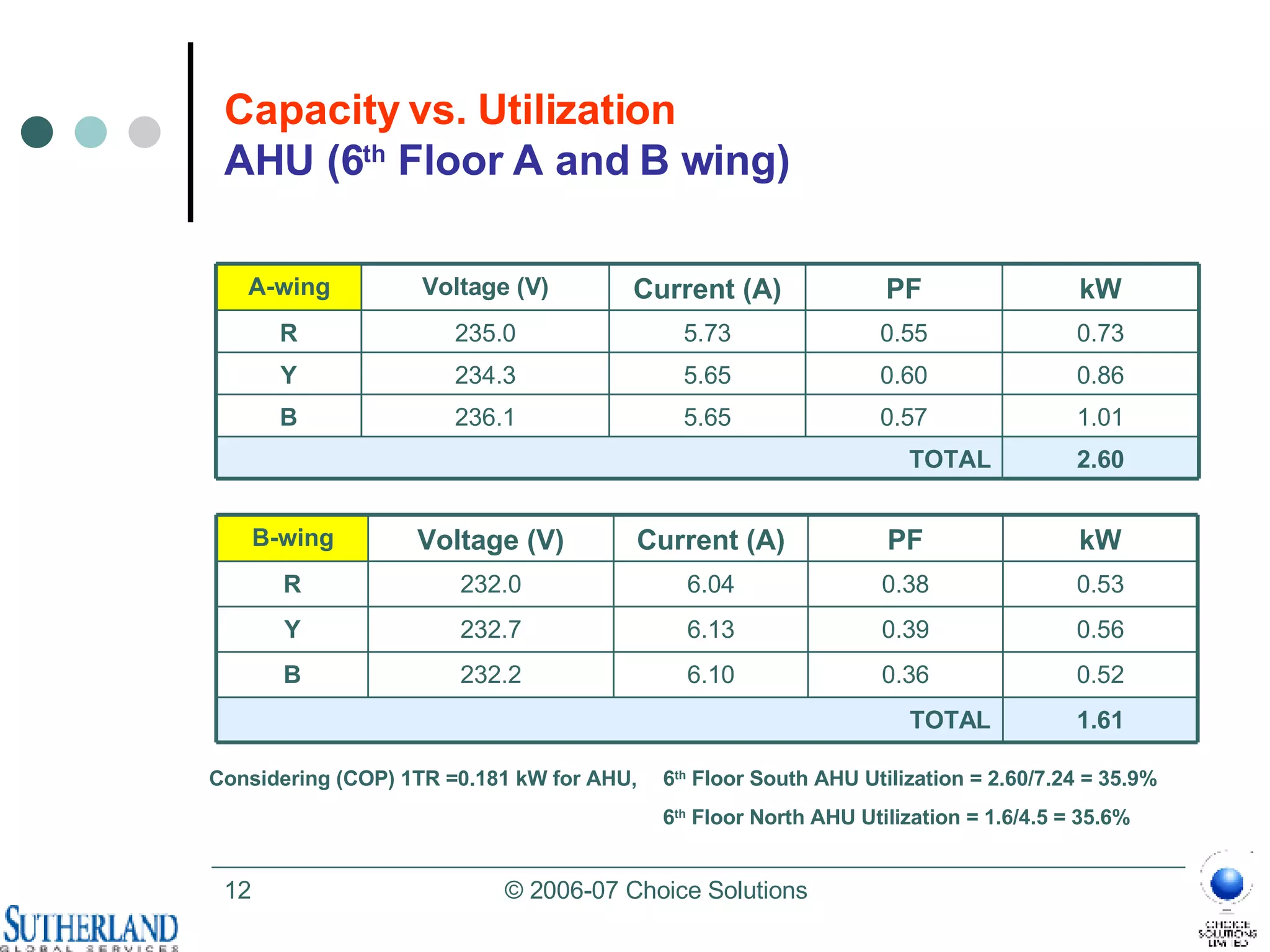
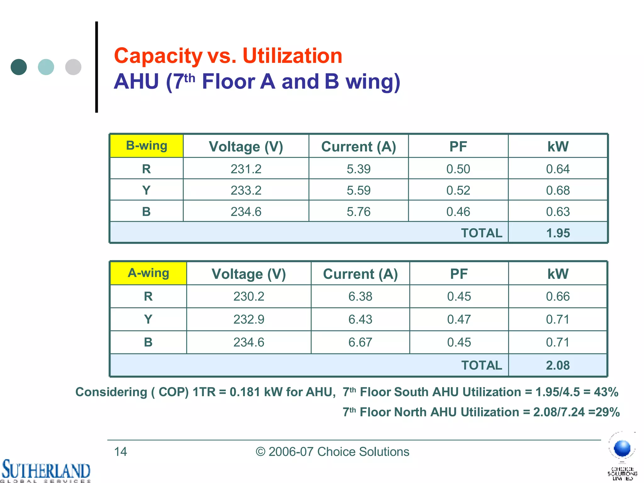
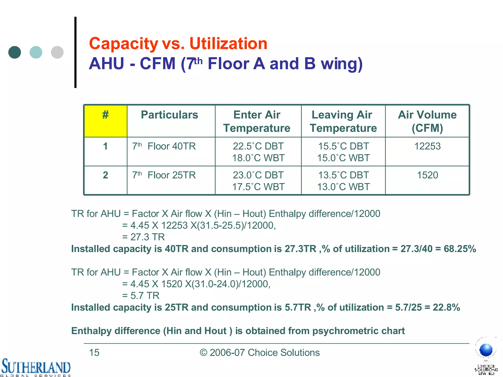
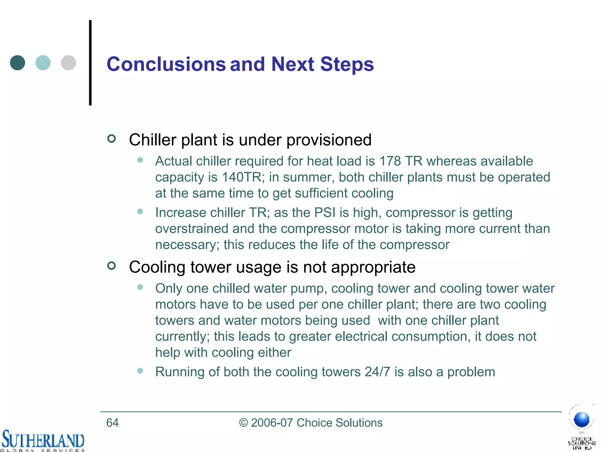
- Actual capacity utilization of chiller plants, AHUs, and other infrastructure is much lower than installed capacity.
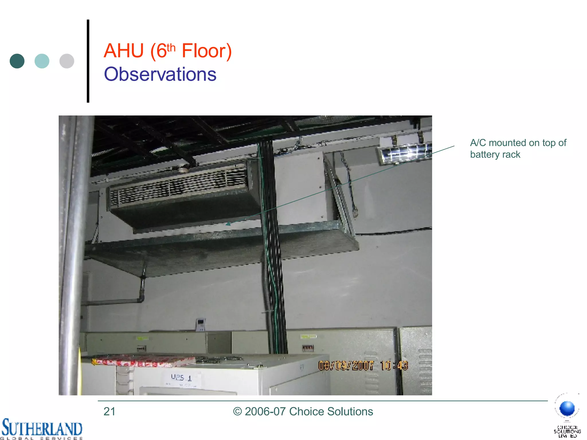
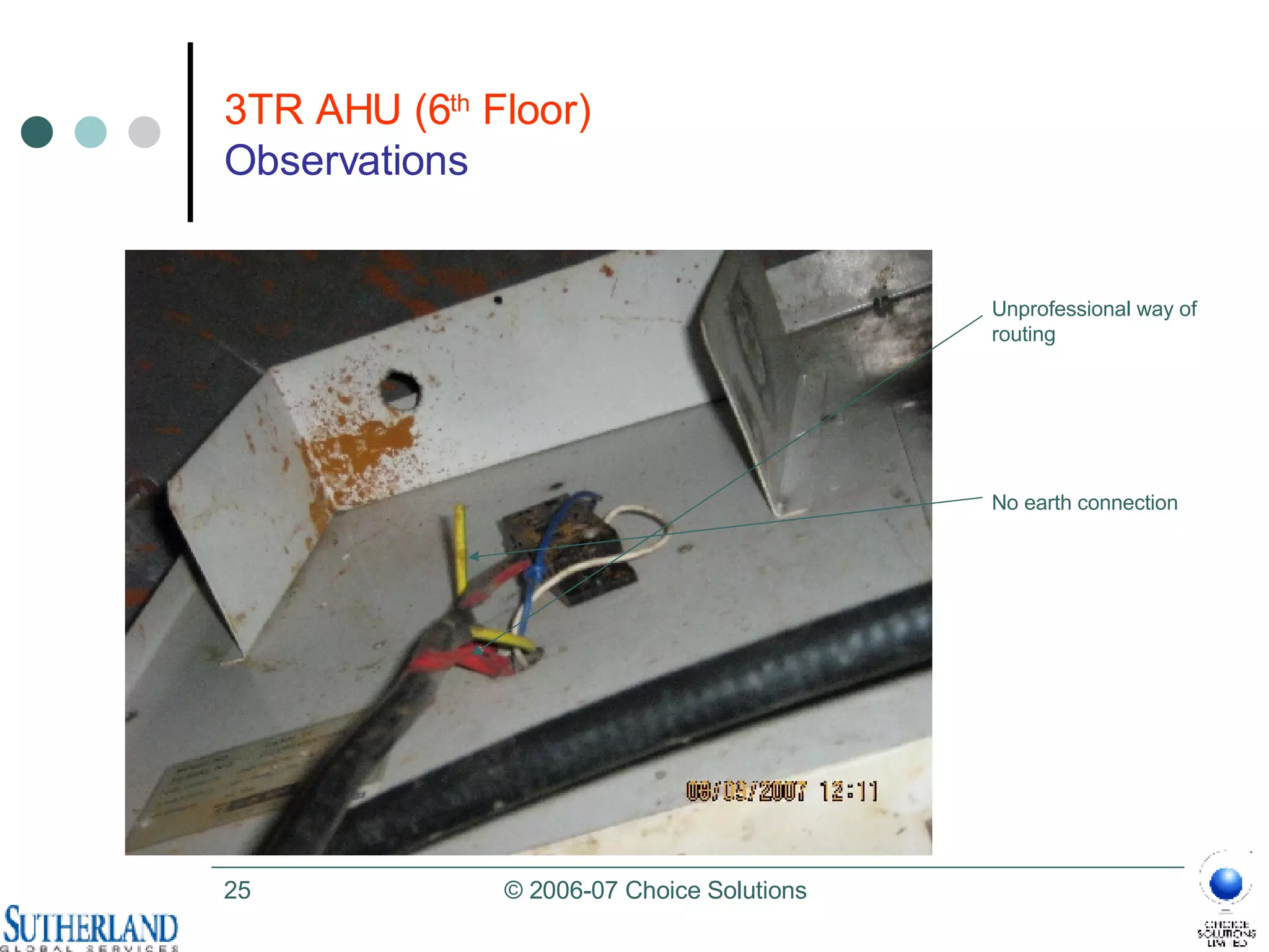
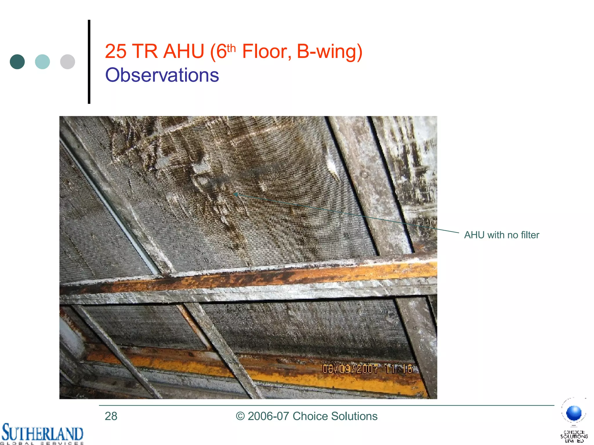
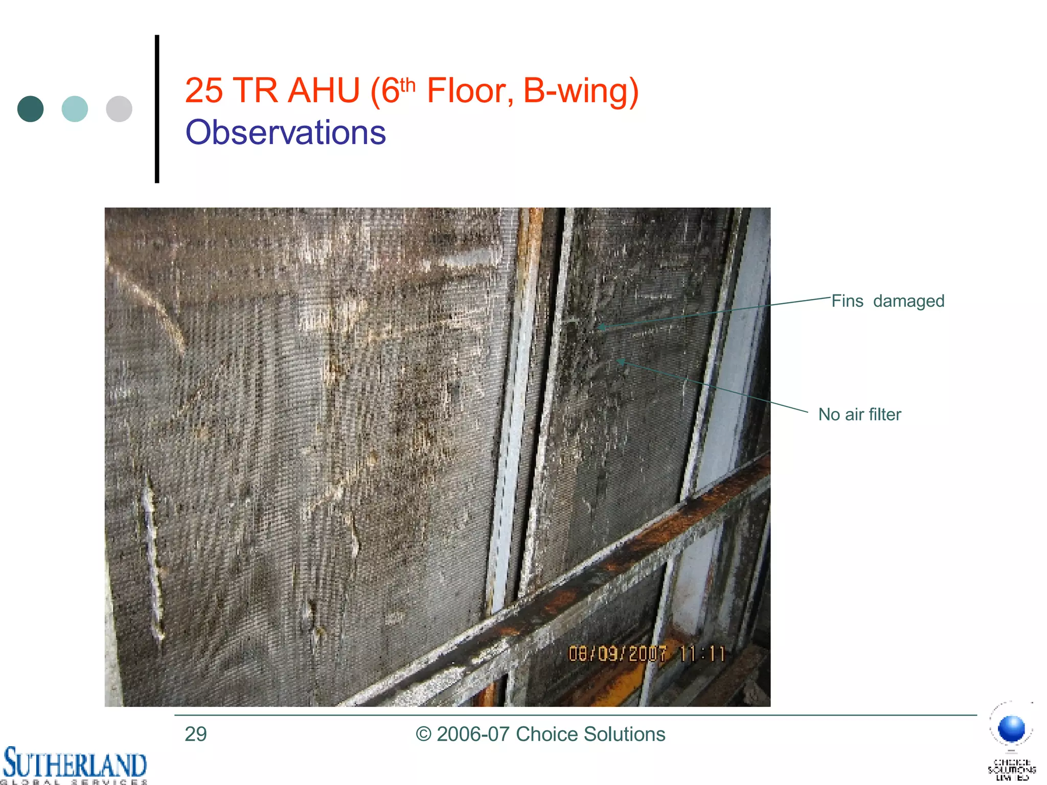
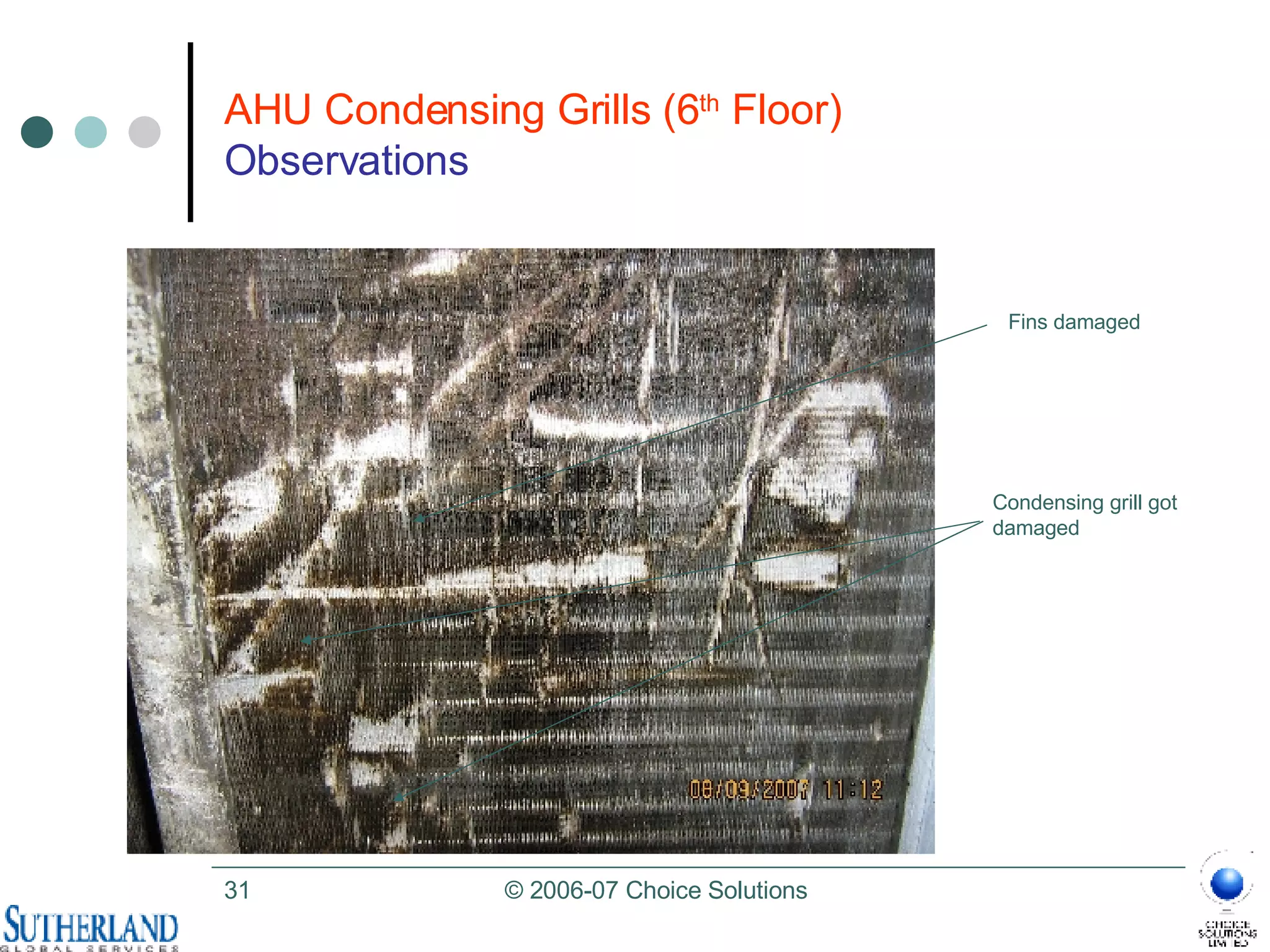
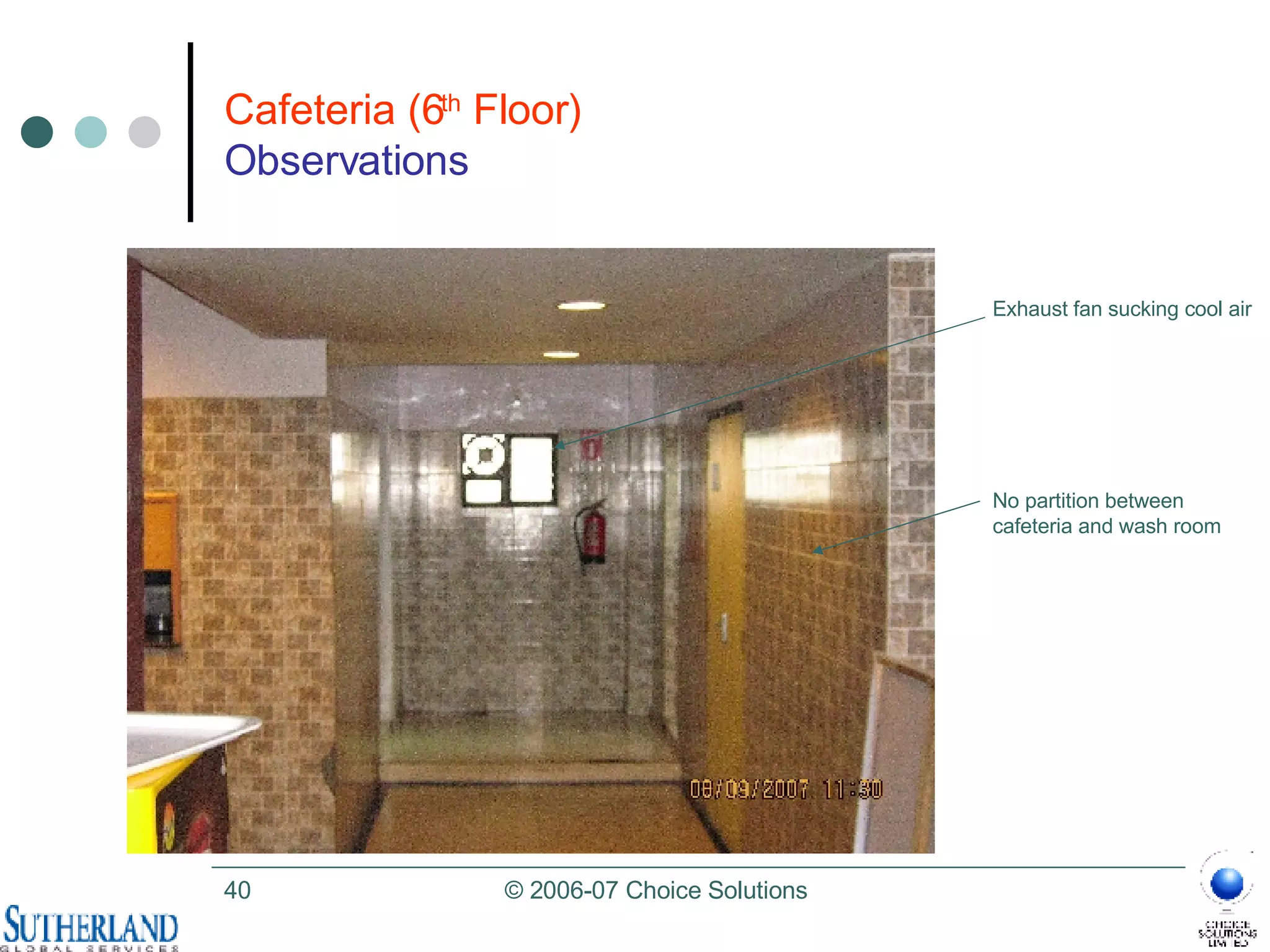
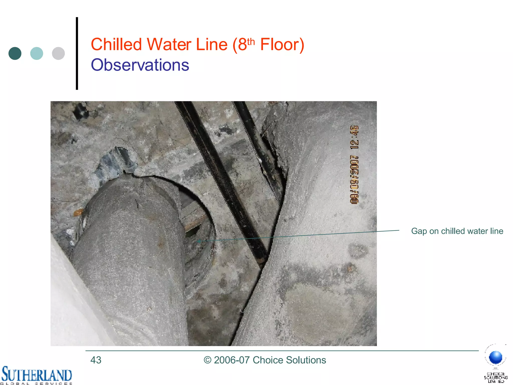
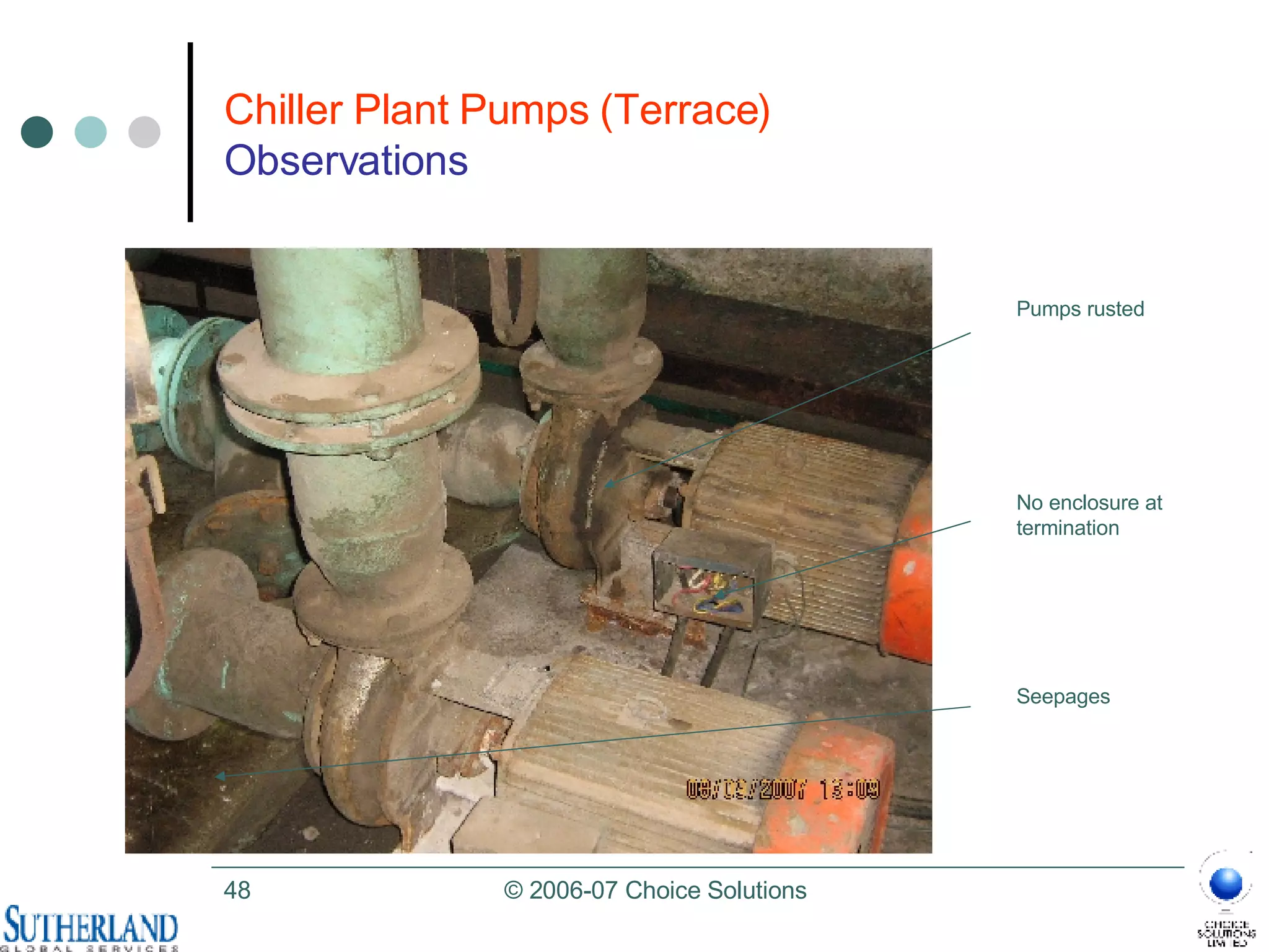
- Several issues were observed with AHUs including lack of filters, damaged components, and improper installation.
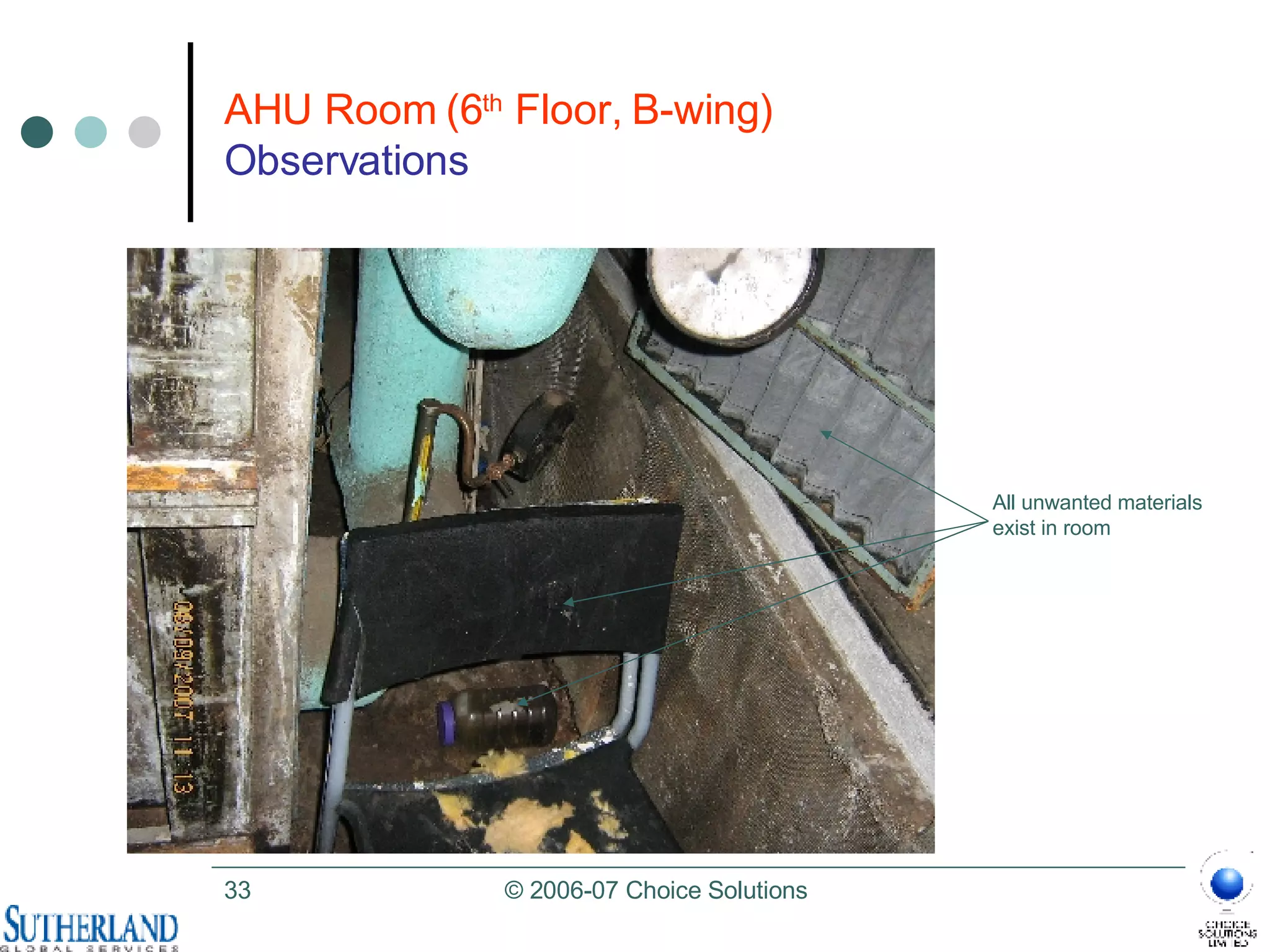
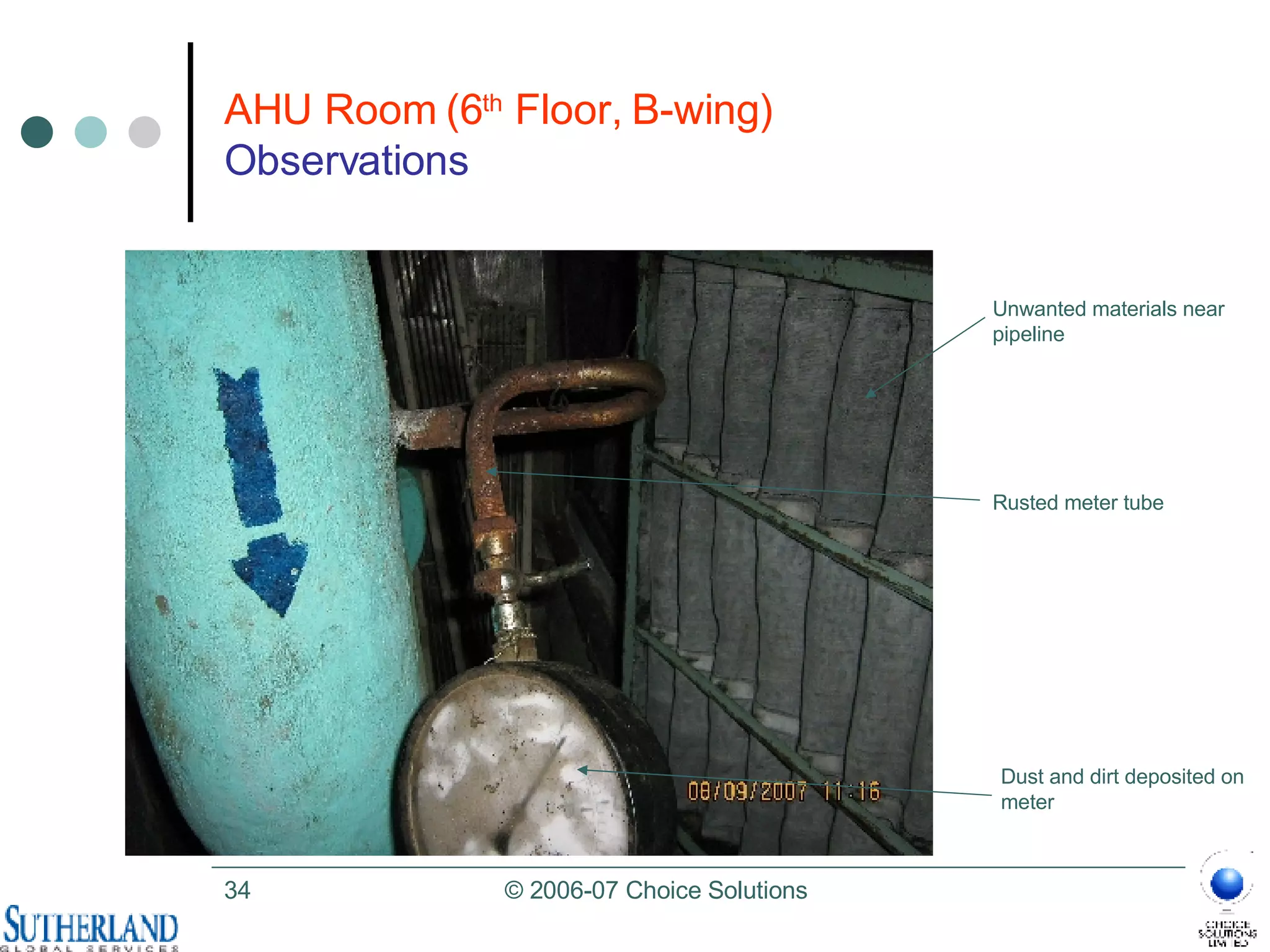
- Facility observations revealed unwanted materials, unclean areas, and other maintenance issues.
Recommendations focus on optimization of the HVAC system, changes to distribution, implementing suggested repairs and upgrades, and ongoing maintenance.


![Choice Solutions Contacts Ramesh R. Senior Solutions Architect, NCPI Choice Solutions, Chennai [email_address] Cell: +91 98410 05183 Tel: +91 44 2436 3391/92/93 http://www.choice-solutions.com Srinivas Chowdary Senior Solutions Architect, NCPI Choice Solutions, Hyderabad [email_address] Cell: +91 98660 79498 Tel: +91 40 2354 7600 http://www.choice-solutions.com](https://image.slidesharecdn.com/sutherlandpadi-audit-results-hvacfinal05-nov-07-1197983086286685-3/75/Sutherland-Padi-Audit-Results-Hvac-Final-05-Nov-07-66-2048.jpg)


