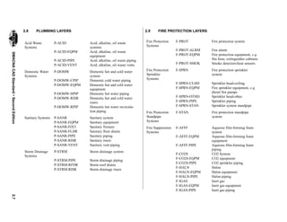
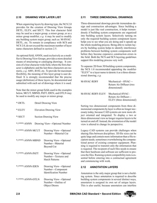
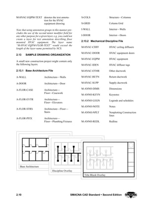
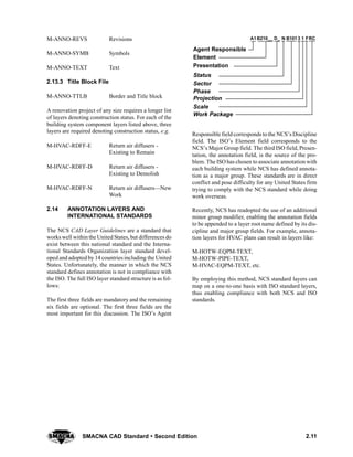
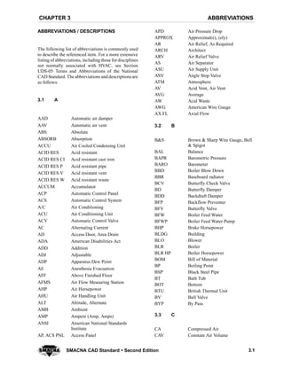
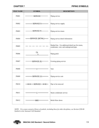
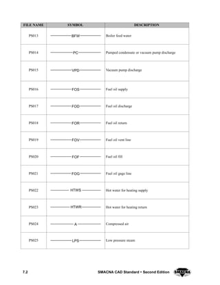
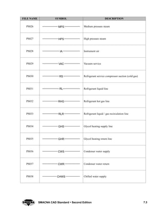
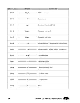
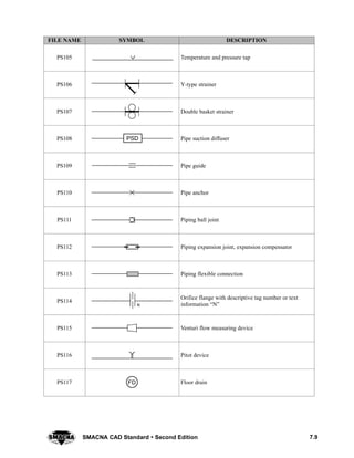
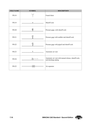
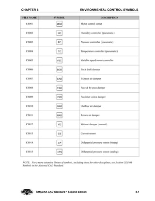
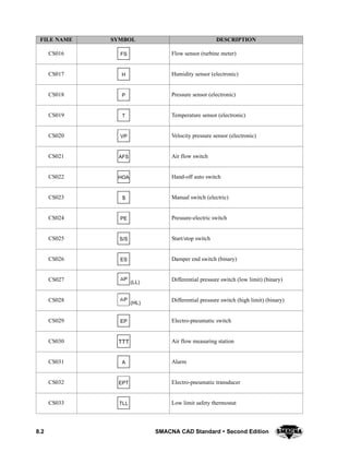
This document provides guidelines for CAD layer standards for mechanical, plumbing and fire protection drawings. It summarizes the SMACNA CAD Standard, which was developed to promote consistency in CAD layer naming and organization. The standard builds upon the National CAD Standard and provides layer naming conventions for elements from various disciplines to allow for efficient sharing and manipulation of data between design professionals using CAD software. It includes recommendations for layer structure, guidelines for layer use, and specific layer names for mechanical, plumbing and fire protection components to facilitate coordination and integration of building information.
Theory and fundamentals of Active Chilled Beams presented at the Illinois Chapter of ASHRAE, February 8, 2011. Presented by Matt Green of Thermosystems.
How to Fix Common Air Conditioner ProblemsNewsTipsTricks
Learn about how to fix common air conditioner problems.Many causes of improper air conditioner operations can be found by visual inspection.If you need a professional air conditioning service you must hire a certified expert.
Piping Training course-How to be an Expert in Pipe & Fittings for Oil & Gas c...Varun Patel
Course Description
Piping a must know skill to work in Oil & Gas and similar Process Industries.
Oil and Gas industry is become a very competitive in the current time. Getting right mentor and right exposer within industry is difficult. With limited training budget spent by company on employee training, it is difficult to acquire the knowledge to success.
Knowing cross-functional skill give you an edge over others in your career success.
This course design based on years of field experience to ensure student will comprehend technical details easily and enjoy overall journey.
Learn in detail every aspect of Pipe & Pipe Fittings used in process industry
•Different types of Pipe, Pipe fittings (Elbow, Tee, reducers, Caps etc.), Flanges, Gaskets, Branch Connection, Bolting materials
•Materials (Metal-Carbon Steel, Stainless Steel, Alloy Steel etc. Non-Metal- PVC/VCM, HDPE, GRE-GRP etc.)
•Manufacturing methods
•Heat treatment requirements
•Inspection and Testing requirements (Non Destructive Testing, Mechanical & Chemical testing)
•Dimensions & Markings requirements
•Code & Standard used in piping
Content and Overview
With 2 hours of content including 30 lectures & 8 Quizzes, this course cover every aspect of Pipe, Pipe fittings, flanges, gaskets, branch connections and bolting material used in Process Piping.
This Course is divided in three parts.
1st part of the course covers fundamental of process industries. In this Part, you will learn about fundamental process piping. You will also learn about Code, Standard & Specification used in process industries.
2nd part cover various types of material used in process industries. In this part, you will learn about Metallic and Non-Metallic material used to manufacture pipe and other piping components.
3rd parts covers in detail about pipe and piping components used in Process piping. In this part we will learn about Industry terminology of Piping components, types of industrial material grade used in manufacturing and entire manufacturing process of these components. You will learn about different manufacturing methods, Heat treatment requirements, Destructive and Non-destructive testing, Visual & Dimensional inspection and Product marking requirements.
Upon completion, you will be able to use this knowledge direct on your Job and you can easily answer any interview question on pipe & fittings.
See the article,
"A Cultural Model for Security in the Post-Desk Era"
commissioned by CA Technologies for this special issue of its Technology Exchange journal.
Welcome to WIPAC Monthly the magazine brought to you by the LinkedIn Group Water Industry Process Automation & Control.
In this month's edition, along with this month's industry news to celebrate the 13 years since the group was created we have articles including
A case study of the used of Advanced Process Control at the Wastewater Treatment works at Lleida in Spain
A look back on an article on smart wastewater networks in order to see how the industry has measured up in the interim around the adoption of Digital Transformation in the Water Industry.
About
Indigenized remote control interface card suitable for MAFI system CCR equipment. Compatible for IDM8000 CCR. Backplane mounted serial and TCP/Ethernet communication module for CCR remote access. IDM 8000 CCR remote control on serial and TCP protocol.
• Remote control: Parallel or serial interface.
• Compatible with MAFI CCR system.
• Compatible with IDM8000 CCR.
• Compatible with Backplane mount serial communication.
• Compatible with commercial and Defence aviation CCR system.
• Remote control system for accessing CCR and allied system over serial or TCP.
• Indigenized local Support/presence in India.
• Easy in configuration using DIP switches.
Technical Specifications
Indigenized remote control interface card suitable for MAFI system CCR equipment. Compatible for IDM8000 CCR. Backplane mounted serial and TCP/Ethernet communication module for CCR remote access. IDM 8000 CCR remote control on serial and TCP protocol.
Key Features
Indigenized remote control interface card suitable for MAFI system CCR equipment. Compatible for IDM8000 CCR. Backplane mounted serial and TCP/Ethernet communication module for CCR remote access. IDM 8000 CCR remote control on serial and TCP protocol.
• Remote control: Parallel or serial interface
• Compatible with MAFI CCR system
• Copatiable with IDM8000 CCR
• Compatible with Backplane mount serial communication.
• Compatible with commercial and Defence aviation CCR system.
• Remote control system for accessing CCR and allied system over serial or TCP.
• Indigenized local Support/presence in India.
Application
• Remote control: Parallel or serial interface.
• Compatible with MAFI CCR system.
• Compatible with IDM8000 CCR.
• Compatible with Backplane mount serial communication.
• Compatible with commercial and Defence aviation CCR system.
• Remote control system for accessing CCR and allied system over serial or TCP.
• Indigenized local Support/presence in India.
• Easy in configuration using DIP switches.
Automobile Management System Project Report.pdfKamal Acharya
The proposed project is developed to manage the automobile in the automobile dealer company. The main module in this project is login, automobile management, customer management, sales, complaints and reports. The first module is the login. The automobile showroom owner should login to the project for usage. The username and password are verified and if it is correct, next form opens. If the username and password are not correct, it shows the error message.
When a customer search for a automobile, if the automobile is available, they will be taken to a page that shows the details of the automobile including automobile name, automobile ID, quantity, price etc. “Automobile Management System” is useful for maintaining automobiles, customers effectively and hence helps for establishing good relation between customer and automobile organization. It contains various customized modules for effectively maintaining automobiles and stock information accurately and safely.
When the automobile is sold to the customer, stock will be reduced automatically. When a new purchase is made, stock will be increased automatically. While selecting automobiles for sale, the proposed software will automatically check for total number of available stock of that particular item, if the total stock of that particular item is less than 5, software will notify the user to purchase the particular item.
Also when the user tries to sale items which are not in stock, the system will prompt the user that the stock is not enough. Customers of this system can search for a automobile; can purchase a automobile easily by selecting fast. On the other hand the stock of automobiles can be maintained perfectly by the automobile shop manager overcoming the drawbacks of existing system.
Hybrid optimization of pumped hydro system and solar- Engr. Abdul-Azeez.pdffxintegritypublishin
Advancements in technology unveil a myriad of electrical and electronic breakthroughs geared towards efficiently harnessing limited resources to meet human energy demands. The optimization of hybrid solar PV panels and pumped hydro energy supply systems plays a pivotal role in utilizing natural resources effectively. This initiative not only benefits humanity but also fosters environmental sustainability. The study investigated the design optimization of these hybrid systems, focusing on understanding solar radiation patterns, identifying geographical influences on solar radiation, formulating a mathematical model for system optimization, and determining the optimal configuration of PV panels and pumped hydro storage. Through a comparative analysis approach and eight weeks of data collection, the study addressed key research questions related to solar radiation patterns and optimal system design. The findings highlighted regions with heightened solar radiation levels, showcasing substantial potential for power generation and emphasizing the system's efficiency. Optimizing system design significantly boosted power generation, promoted renewable energy utilization, and enhanced energy storage capacity. The study underscored the benefits of optimizing hybrid solar PV panels and pumped hydro energy supply systems for sustainable energy usage. Optimizing the design of solar PV panels and pumped hydro energy supply systems as examined across diverse climatic conditions in a developing country, not only enhances power generation but also improves the integration of renewable energy sources and boosts energy storage capacities, particularly beneficial for less economically prosperous regions. Additionally, the study provides valuable insights for advancing energy research in economically viable areas. Recommendations included conducting site-specific assessments, utilizing advanced modeling tools, implementing regular maintenance protocols, and enhancing communication among system components.
Overview of the fundamental roles in Hydropower generation and the components involved in wider Electrical Engineering.
This paper presents the design and construction of hydroelectric dams from the hydrologist’s survey of the valley before construction, all aspects and involved disciplines, fluid dynamics, structural engineering, generation and mains frequency regulation to the very transmission of power through the network in the United Kingdom.
Author: Robbie Edward Sayers
Collaborators and co editors: Charlie Sims and Connor Healey.
(C) 2024 Robbie E. Sayers
Saudi Arabia stands as a titan in the global energy landscape, renowned for its abundant oil and gas resources. It's the largest exporter of petroleum and holds some of the world's most significant reserves. Let's delve into the top 10 oil and gas projects shaping Saudi Arabia's energy future in 2024.
NO1 Uk best vashikaran specialist in delhi vashikaran baba near me online vas...Amil Baba Dawood bangali
Contact with Dawood Bhai Just call on +92322-6382012 and we'll help you. We'll solve all your problems within 12 to 24 hours and with 101% guarantee and with astrology systematic. If you want to take any personal or professional advice then also you can call us on +92322-6382012 , ONLINE LOVE PROBLEM & Other all types of Daily Life Problem's.Then CALL or WHATSAPP us on +92322-6382012 and Get all these problems solutions here by Amil Baba DAWOOD BANGALI
#vashikaranspecialist #astrologer #palmistry #amliyaat #taweez #manpasandshadi #horoscope #spiritual #lovelife #lovespell #marriagespell#aamilbabainpakistan #amilbabainkarachi #powerfullblackmagicspell #kalajadumantarspecialist #realamilbaba #AmilbabainPakistan #astrologerincanada #astrologerindubai #lovespellsmaster #kalajaduspecialist #lovespellsthatwork #aamilbabainlahore#blackmagicformarriage #aamilbaba #kalajadu #kalailam #taweez #wazifaexpert #jadumantar #vashikaranspecialist #astrologer #palmistry #amliyaat #taweez #manpasandshadi #horoscope #spiritual #lovelife #lovespell #marriagespell#aamilbabainpakistan #amilbabainkarachi #powerfullblackmagicspell #kalajadumantarspecialist #realamilbaba #AmilbabainPakistan #astrologerincanada #astrologerindubai #lovespellsmaster #kalajaduspecialist #lovespellsthatwork #aamilbabainlahore #blackmagicforlove #blackmagicformarriage #aamilbaba #kalajadu #kalailam #taweez #wazifaexpert #jadumantar #vashikaranspecialist #astrologer #palmistry #amliyaat #taweez #manpasandshadi #horoscope #spiritual #lovelife #lovespell #marriagespell#aamilbabainpakistan #amilbabainkarachi #powerfullblackmagicspell #kalajadumantarspecialist #realamilbaba #AmilbabainPakistan #astrologerincanada #astrologerindubai #lovespellsmaster #kalajaduspecialist #lovespellsthatwork #aamilbabainlahore #Amilbabainuk #amilbabainspain #amilbabaindubai #Amilbabainnorway #amilbabainkrachi #amilbabainlahore #amilbabaingujranwalan #amilbabainislamabad
Student information management system project report ii.pdfKamal Acharya
Our project explains about the student management. This project mainly explains the various actions related to student details. This project shows some ease in adding, editing and deleting the student details. It also provides a less time consuming process for viewing, adding, editing and deleting the marks of the students.
Forklift Classes Overview by Intella PartsIntella Parts
Discover the different forklift classes and their specific applications. Learn how to choose the right forklift for your needs to ensure safety, efficiency, and compliance in your operations.
For more technical information, visit our website https://intellaparts.com
Vaccine management system project report documentation..pdfKamal Acharya
The Division of Vaccine and Immunization is facing increasing difficulty monitoring vaccines and other commodities distribution once they have been distributed from the national stores. With the introduction of new vaccines, more challenges have been anticipated with this additions posing serious threat to the already over strained vaccine supply chain system in Kenya.
3. SMACNA CAD
STANDARD
SECOND EDITION – JULY 2001
SHEET METAL AND AIR CONDITIONING CONTRACTORS’
NATIONAL ASSOCIATION, INC.
4201 Lafayette Center Drive
Chantilly, VA 20151--1209
4. SMACNA CAD STANDARD
COPYRIGHTE2001
All Rights Reserved
by
SHEET METAL AND AIR CONDITIONING CONTRACTORS’
NATIONAL ASSOCIATION, INC.
4201 Lafayette Center Drive
Chantilly, VA 20151--1209
Printed in the U.S.A.
FIRST EDITION -- 1996
SECOND EDITION – JULY 2001
Except as allowed in the Notice to Users and in certain licensing contracts, no part of this book may be
reproduced, stored in a retrievable system, or transmitted, in any form or by any means, electronic,
mechanical, photocopying, recording, or otherwise, without the prior written permission of the publisher.
5. iiiSMACNA CAD Standard Second Edition
FOREWORD
The SMACNA CAD STANDARD (SCS), formerly called CADD Symbols and Layering Guidelines in its first edition,
embraces the idea that computer-aided design (CAD) has become indispensable to the architecture/ engineering/
construction (AEC) industry. Not only has CAD software improved drafting efficiency and the overall productivity
of the construction professional, but now building owners are realizing the potential of automated controls and elec-
tronic record keeping and are requesting data in electronic format from construction professionals.
Now that they have learned to communicate with the computer, many designers and builders are using computers to
improve communications with each other. In order to share electronic information efficiently, it’s essential that all
parties speak the same language. For members of the endorsing organizations, it’s important that the mechanical,
plumbing, and fire protection information be labeled and located consistently in CAD files so that it is easily found
and manipulated. For building owners and design professionals, it’s important that such data be consistently stored
withintheirown CADfiles inaccord witha mutuallyagreed protocol or standard. Toensure consistencyit isimportant
to organize data into predefined “layers”, to apply identical graphic symbols to components, and to use consistent ter-
minology and abbreviations.
SCS is designed to encourage consistency by building upon the second edition of the National CAD Standard (NCS)
published by the National Institute of Building Sciences in 2001. NCS incorporates the efforts of the American Insti-
tute of Architects (AIA) and its CAD Layer Guidelines as well as the Construction Specifications Institute (CSI) and
its Uniform Drawing System. As an organization with contributing members on the NCS Committee, SMACNA is
committed to improving electronic communication between members of the AEC community and the overall quality
of their work.
In this current edition of SCS, SMACNA has extended NCS by drawing upon the considerable experience of its own
CADD Task Force. SCS articulates the CAD standards that will enable SMACNA members and the rest of the AEC
community to apply CAD effectively to mechanical, fire protection, and plumbing design and construction.
This document is available in electronic format by accessing http://www.smacna.org on the Internet.
SHEET METAL AND AIR CONDITIONING CONTRACTORS’
NATIONAL ASSOCIATION, INC.
6. iv SMACNA CAD Standard Second Edition
CADD TASK FORCE
Richard E. Brown, Chairman
Rabe Environmental Systems, Inc.
Erie, Pennsylvania
Robert Buckley, Jr.
Anderson, Rowe & Buckley, Inc.
San Francisco, California
Ken Castro
TRI-C Sheet Metal, Inc.
Cleveland, Ohio
Roy Jensen
MechOne, Inc.
Colorado Springs, Colorado
Gary L. Joaquin, Technical Writer
JLG & Associates
Annandale, Virginia
G. A. Navas, Staff Liaison
SMACNA, Inc.
Chantilly, Virginia
FORMER COMMITTEE MEMBERS
AND OTHER CONTRIBUTORS
The following individuals and organizations participated in the development of the CADD Symbols and Layering
Guidelines, 1st edition.
SMACNA COMPUTER COMMITTEE
Gary C. Carvetta, Chairman
Triangle Mechanical, Inc.
Phillip Gillespie
Brad Snodgrass, Inc.
Mark Allan Siebert
Production Services, Inc.
Mark Watson
Climate Engineers, Inc.
OTHER CONTRIBUTORS
Central Indiana Chapter CAD Users Group
Indianapolis, Indiana
Phillip E. Gillespie, Chairman
Brad Snodgrass, Inc.
Gary Baldwin
Apex Ventilating Company, Inc.
Curtis Bond
Brad Snodgrass, Inc.
Robert L Goshert
Simon Property Group, Inc.
Michael Johnson
Brad Snodgrass, Inc.
Phil Krisch
Brad Snodgrass, Inc.
Darryl A. McClelland
McClelland Consulting
Rick McKee
Brad Snodgrass, Inc.
Robert Overton
Indiana Government Center—Public Works Division
Bill Paradise
Apex Ventilating Company, Inc.
Greg Stephens
Musset Nicholas and Associates, Inc.
Loyd Vandagriff
Brad Snodgrass, Inc.—Ford Motor Co.
Michael L. Wentworth
BSA Design
7. SMACNA CAD Standard Second Edition v
NOTICE TO USERS
OF THIS PUBLICATION
1. DISCLAIMER OF WARRANTIES
a) The Sheet Metal and Air Conditioning Contractor’s National Association (“SMACNA”) provides its product for informational
purposes.
b) The product contains “Data” which is believed by SMACNA to be accurate and correct but the data, including all information,
ideas and expressions therein, is provided strictly “AS IS”, with all faults. SMACNA makes no warranty either express or implied
regarding the Data and SMACNA EXPRESSLY DISCLAIMS ANY IMPLIED WARRANTIES OF MERCHANTABILITY OR
FITNESS FOR PARTICULAR PURPOSE.
c) By using the data contained in the product user accepts the Data “AS IS” and assumes all risk of loss, harm or injury that may result
from its use. User acknowledges that the Data is complex, subject to faults and requires verification by competent professionals, and
that modification of parts of the Data by user may impact the results or other parts of the Data.
d) IN NO EVENT SHALL SMACNA BE LIABLE TO USER, OR ANY OTHER PERSON, FOR ANY INDIRECT, SPECIAL OR
CONSEQUENTIAL DAMAGES ARISING, DIRECTLY OR INDIRECTLY, OUT OF OR RELATED TO USER’S USE OF
SMACNA’S PRODUCT OR MODIFICATION OF DATA THEREIN. This limitation of liability applies even if SMACNA has been
advised of the possibility of such damages. IN NO EVENT SHALL SMACNA’S LIABILITY EXCEED THE AMOUNT PAID BY
USER FOR ACCESS TO SMACNA’S PRODUCT OR $1,000.00, WHICHEVER IS GREATER, REGARDLESS OF LEGAL
THEORY.
e) User by its use of SMACNA’s product acknowledges and accepts the foregoing limitation of liability and disclaimer of warranty
and agrees to indemnify and hold harmless SMACNA from and against all injuries, claims, loss or damage arising, directly or indi-
rectly, out of user’s access to or use of SMACNA’s product or the Data contained therein.
2. ACCEPTANCE
This document or publication is prepared for voluntary acceptance and use within the limitations of application defined herein, and
otherwise as those adopting it or applying it deem appropriate. It is nota safety standard. Itsapplication fora specificproject iscontin-
genton adesignerorotherauthority defining aspecificuse.SMACNAhasno power orauthority to police orenforce compliancewith
the contents of this document or publication and it has no role in any representations by other parties that specific components are, in
fact, in compliance with it.
3. AMENDMENTS
The Association may, from time to time, issue formal interpretations or interim amendments, which can be of significance between
successive editions.
4. PROPRIETARY PRODUCTS
SMACNAencouragestechnologicaldevelopmentin theinterestofimproving theindustry forthepublicbenefit.SMACNAdoesnot,
however, endorse individual manufacturers or products.
5. FORMAL INTERPRETATION
a) A formal interpretation of the literal text herein or the intent of the technical committee or task force associated with the document
or publication is obtainable only on the basis of written petition, addressed to the Technical Resources Department and sent to the
Association’s national office in Chantilly, Virginia. In the event that the petitioner has a substantive disagreement with the interpreta-
tion, an appeal may be filed with the Technical Resources Committee, which has technical oversight responsibility. The request must
pertain to a specifically identified portion of the document that does not involvepublished textwhich providesthe requested informa-
tion. In considering such requests, the Association will not review or judge products or components as being in compliance with the
document or publication. Oral and written interpretations otherwise obtained from anyone affiliated with the Association are unoffi-
cial. This procedure does not prevent any committee or task force chairman, member of the committee or task force, or staff liaison
from expressing an opinion on a provision within the document, provided that such person clearly states that the opinion is personal
and does not represent an official act of the Association in any way, and it should not be relied on as such. The Board of Directors of
SMACNA shall have final authority for interpretation of this standard with such rules or procedures as they may adopt for processing
same.
b) SMACNA disclaims any liability for any personal injury, property damage, or other damage of any nature whatsoever, whether
special, indirect, consequential or compensatory, direct or indirectly resulting from the publication,use of,or relianceupon thisdocu-
ment. SMACNA makes no guaranty or warranty as to the accuracy or completeness of any information published herein.
6. APPLICATION
a) Any standards contained in this publication were developed using reliable engineering principles and research plus consultation
with, and information obtained from, manufacturers, users, testing laboratories, and others having specialized experience. They are
8. vi SMACNA CAD Standard Second Edition
subject to revision as further experience and investigation may show is necessary or desirable. Construction and products which com-
ply with these Standards will not necessarily be acceptable if, when examined and tested, they are found to have other features which
impair the result contemplated by these requirements. The Sheet Metal and Air Conditioning Contractors’ National Association and
other contributors assume no responsibility and accept no liability for the application of the principles or techniques contained in this
publication. Authorities considering adoption of any standards contained herein should review all federal, state, local, and contract
regulations applicable to specific installations.
b) In issuing and making this document available, SMACNA is not undertaking to render professional or other services for or on
behalf of any person or entity. SMACNA is not undertaking to perform any duty owed to any person or entity to someone else. Any
person or organization using thisdocument should rely on his, heror itsown judgementor, asappropriate, seek the adviceof acompe-
tent professional in determining the exercise of reasonable care in any given circumstance.
7. REPRINT PERMISSION
Non--exclusive, royalty--free permission is granted to government and private sector specifying authorities to reproduce only any
construction details found herein in their specifications and contract drawings prepared for receipt of bids on new construction and
renovation work within the United States and its territories, provided that the material copied is unaltered in substance and that the
reproducer assumes all liability for the specific application, including errors in reproduction.
8. THE SMACNA LOGO
The SMACNA logo is registered as a membership identification mark. The Association prescribes acceptable use of the logo and
expressly forbids the use of it to represent anything other than possession of membership. Possession of membership and use of the
logo in no way constitutes or reflects SMACNA approval of any product, method, or component. Furthermore, compliance of any
such item with standards published or recognized by SMACNA is not indicated by presence of the logo.
15. INTRODUCTIONCHAPTER 1
1.1SMACNA CAD Standard Second Edition
1.1 HOW TO USE THIS PUBLICATION
This publication is designed to be an easy to use quick
reference guide. The information it contains is orga-
nized and presented in three discrete categories: lay-
ers, abbreviations, and symbols.
Chapter 2 describes standard layers based upon the
National CAD Standard (NCS) which include many
new additions introduced by members of SMACNA’s
CADD Task Force who participated on the NCS Com-
mittee. This flexible standard is well documented and
provides several concrete examples of efficient layer
use.
Chapter 3 provides a list of standard abbreviations
which are a combination of the abbreviations found in
SMACNA’s first edition of the CADD Symbols and
Layering Guidelines and the standard abbreviations
listed in the Construction Specification Institute’s
Uniform Drawing System, part of NCS.
Chapters 4 though 9 list standard drafting symbols,
grouped by construction component category. These
symbols come from a variety of sources and are now
assembled together into one comprehensive source to
be used by the mechanical trades. All of the symbol
blocks in this publication may be downloaded from
http://www.smacna.org.
Experienced CAD users and novices alike can turn to
Appendix A for a more complete overview of the re-
quirements for implementing an office CAD standard.
Useful checklists anda CADdocument submittal form
are provided in the remaining appendices.
1.2 READER FEEDBACK
The layers, abbreviations, symbols, and protocols de-
scribed in this book are part of an evolving standard.
Users are encouraged to offer comments and sugges-
tions after they have reviewed and used this material
in practice. Please send your feedback to:
SMACNA
Attn: SMACNA CAD STANDARD
4201 Lafayette Center Drive
Chantilly, VA 20151-1209
16. 1.2 SMACNA CAD Standard Second Edition
THIS PAGE INTENTIONALLY LEFT BLANK
19. LAYERSCHAPTER 2
2.1SMACNA CAD Standard Second Edition
2.1 WHAT ARE CAD LAYERS?
One of the best ways to understand CAD layers is to
imagine drafting manually on many stacked sheets or
layers of transparent acetate. Starting at the bottom of
the pile is a layer of acetate on which only the building
walls are drawn. Following an office standard, the
drafter might place another acetate layer ontop ofthat,
and while seeing through to the wall layer, draw the
door swings. Another layer might contain only the air
conditioning equipment. When all the layers are
stacked and aligned, a complete, if complex and
crowded, picture of the entire building is viewed. Se-
lected layers can be removed and recombined to give
an uncluttered view of items of particular interest. For
example, an HVAC contractor might select only the
sheets with the walls and the air conditioning equip-
ment. A construction supervisor might want to ex-
amine the piping and ductwork in isolation to ensure
that there are no interferences that will create costly
conflicts during construction.
CAD systems manipulate layers of information faster
than any manual drafting process. Using CAD soft-
ware, drafters can turn layers on and off, controlling
which layers are displayed and edited at any given
time, for any given purpose. When properly used,
CAD systems generate drawings that are simpler and
easiertoread. Forexample, a complex joblike a hospi-
tal may have so much mechanical work that to display
it all in one drawingwould be completely illegible. Al-
though the drawing data may all reside in a single file
for computer storage efficiency, a crew installing ter-
minal units doesn’t necessarily need to see all of the
ductwork and piping. They may only need a drawing
on the job site that displays only the wall and terminal
unit layers. CAD systems provide the means to display
only the most relevant information.
2.2 WHY ARE CAD LAYERS
IMPORTANT?
Adhering to a consistent and mutually well understood
CAD layer standard gives professionals a common
communications vocabulary which is vital today since
so many construction drawings and so much data is
shared electronically. Without a CAD layer standard,
sharing drawings between two CADsystems orsimply
tryingto readelectronic drawingsprepared byanother,
even in one’s own office, can be difficult, time con-
suming, or even impossible. Streamlining the flow of
data through the use of a consistent layering standard
means less duplication of effort in producing draw-
ings, more accurate bids, reduced construction time
and costs, and fewer construction errors in the field.
2.3 A SIMPLER SMACNA CAD LAYER
GUIDELINE
The CADLayer Guidelinesin thiscurrent editionhave
been revised and simplified substantially since they
were first released in SMACNA’s 1996 edition of the
CADD Symbols and Layering Guidelines, and with
good reason. After careful examination, SMACNA
determined that most of the layers variables defined
for material types, classification and gages, and spe-
cial conditions identified in the first edition are more
appropriately stored in CAD drawing files as attribute
data and do not necessarily require their own separate
layers. Using attribute data performsa similarfunction
for character based data, that layers do for visual data.
Layers enable CAD users to organize building infor-
mation into visual reports where layers are selectively
turned on and off to produce a drawing displaying spe-
cific information. Attribute data enables character
based data to be stored in a drawing, typically at the
block level as a property, where it can be selectively
retrieved for the purpose of generating character based
reports summarizing important properties like project
cost or existing building conditions.
2.4 BACKGROUND OF THE SMACNA
CAD STANDARD
SMACNA’s first edition CAD Layer Guidelines de-
fined layer names with a maximum length of eight
characterstospeeddata entry. CADsystems like Auto-
CADR were more character basedand, typically, CAD
users typed in layer names, so the shorter the name the
better. Today’s CAD systems support layer names up
to 255 characters in length with much greater flexibili-
ty. This is the environment in which the latest version
of the National CAD Standard (NCS) layer guidelines
was developed by the American Institute of Archi-
tects. This standard is a much more legible one using
a maximum of 18 characters. In an effort to comply
with NCS and the larger AEC community SMACNA
has adopted the NCSstandard inprinciple andexpand-
ed upon it, providing standard layer names for a wider
range of mechanical, fire protection, and plumbing
components. Credit should be given to the University
of Minnesota whose Department of FacilitiesManage-
ment made substantial contributions to SMACNA’s
effort to refine its layer standard. Credit should also be
given to the Department of Defense’s Tri-Services
CAD/GIS Center and the role that it has played instan-
dardizing the use of CAD layers.
20. 2.2 SMACNA CAD Standard Second Edition
2.5 LAYER STRUCTURE
Recent CAD software releases have supported much
longer layer names making it easier to recognize the
contents of a layer from its name alone. While CAD
software can support layer names of up to 255 charac-
ters, the ultimate limitation is the human interface;
CAD users can only comprehend and manipulate layer
names that are of a practical length. So rather than use
the maximum number of characters in a layer name,
SMACNA has adopted the NCS standard for its brev-
ity, clarity, and consistency. SMACNA’s layer naming
standard uses a minimum of 6 characters up to a maxi-
mum of 18 characters. Hyphens are inserted at precise
positions to separate layer names into logical and easi-
ly readable components as follows:
Discipline
Major Group
Minor Group
Minor Group Modifier
Status
M NHVAC SDFF XXXX
where each field is defined as follows:
Discipline is a mandatory one-character field describ-
ing the discipline under whicha layer’scontent iscate-
gorized. SMACNA recommends three disciplines, F
for Fire Protection, M for Mechanical, and P for
Plumbing, resulting in standard layer names like
F-PROT, M-HVAC and P-STRM.
It is important to note explicitly that the purpose of the
discipline field is not to identify the author of a layer.
Disciplines frequently do work traditionally per-
formed by other disciplines, especially on smaller pro-
jects. Using the discipline field to denote layer author-
ship would introduce inconsistency into layer names,
not only across industries, but even with small offices,
thus this interpretation is not supported by the SMAC-
NA standard.
SMACNA recognizes that NCS has expanded its own
discipline field to include anoptional secondcharacter
where required. SMACNA supports the expansion of
this field where it is used to further denote layer con-
tent, not authorship.
Major Group is a mandatory four-character field de-
scribing buildingsystems. Generally, major groupsare
associated with a specific discipline; however, it is
possible for the responsibility of a major group to be
shared by two disciplines resulting in layer names like
M-HVAC and P-HVAC. Annotation, *-ANNO-*, is
the only major group that is not a building system. It
is described separately in section 2.12.
Minor Group is an optional four-character field used
to further differentiate major groups, e.g. the need to
separate supply and return ductwork results in the lay-
er names M-HVAC-SDFF and M-HVAC-RDFF.
While the majority of minor groups modify a specific
major group, four minor groups may be used tomodify
virtually all of the major groups:
ELEV: denotes an elevation view,
e.g. M-HVAC-ELEV
IDEN: denotes symbols or text
that need to remain on
even when text layers are
turned off, e.g. M-HVAC-
IDEN.
PATT: denotes hatch patterns,
e.g. M-HVAC-PATT.
RDME: denotes read-me layer,
text not to be plotted, e.g.
M-HVAC-RDME
Minor Group Modifier is an optional four-character
field used to further differentiate minor groups, e.g.
M-HVAC-DOOR-IDEN denotes labels that identify
mechanical access doors.
Status is an optional one character field describing the
construction state of a layer’s contents:
N New Work
E Existing to Remain
D Existing to Demolish
F Future Work
T Temporary Work
M Items to Be Moved
R Relocated Items
X Not in Contract
1-9 Phase Numbers
A As Built
e.g. M-HVAC-RETN-D denotes a layer containing
Mechanical-Heating, Ventilation, and Air Condition-
ing - Return Ducts - To Be Demolished.
21. 2.3SMACNA CAD Standard Second Edition
2.6 GUIDELINES FOR LAYER USE
1. Use only the layers that your work requires.
Develop a list of standard layers for your
practice by selecting layers from the standard
lists provided in these guidelines. If you do
not find all of the layer names that you need,
create your own new majorgroups alongwith
new minor group and minor group modifier
fields. These guidelines are intended to be
flexible and toprovide a structure from which
to define new layers.
2. It is important that each layername fieldhave
exactly the same number of characters that
are specified in this standard, e.g. the major
group field must contain four and exactly
four characters. Adhering to a consistent lay-
er standard enables each character position in
a layer name to retain the same meaning,
making it easier to turn groups of layers on
and off with layer name wild cards.
3. Don’t use more layer fields than your work
requires. The minimum layer name requires
only the mandatory fields, discipline and ma-
jor group. These are frequently sufficient to
describe the contents of a layer.
4. Layer fields are interchangeable and may be
combined in an infinite number of ways as
long as they describe a system that actually
exists, e.g. P-CHIM-FLDR denoting floor
drains installed in a chimney by a plumbing
discipline is not a physically meaningful lay-
er name.
5. To be in compliance with these layer guide-
lines, do not rename layers that are already
defined, e.g. M-HVAC-EQPM is in com-
pliance while M-HVAC-EQPT is not.
6. To ensure consistent layer use in your prac-
tice, create drawing template files containing
standard layers for each type of drawing that
you produce. Use script files to add layers to
template files. Creating new layers manually
can be very error prone and should be avoi-
ded. Develop scripts to create layers required
fora majorgroupora set ofmajor groups. De-
velop versions of these script files, one for
new construction with its shorter layer list
and another for renovation projects with the
longer layer list required to describe
construction status, to name but a couple of
conditions. Use these scripts in combination
to produce template files for the simplest and
the most complex projects. Scripts may also
be used to add new layers to active projects
whose scope has increased.
Note that the latest CAD software releases
now include menus to develop drawing tem-
plate files using NCS layers, finally offering
a solution to the problem of creating drawing
template files that are more efficient than
writing and running script files.
7. Generally, plan drawings pose the most chal-
lenging layer coordination effort, since the
work of several disciplines must be integra-
ted. Details and three-dimensional drawings
have their own special requirements which
are covered in their own separate section.
8. Use hatch patterns sparingly to avoid making
drawings too difficult to read. Place hatch
patterns on their own separate “PATT” layer
to prevent them from interfering with precise
drafting where they can clutter a drawing
with misleading snap coordinates. Place
hatch pattern boundary polygons on a sepa-
rate layer, usually the nonplot layer, “NPLT”,
for all of the same reasons and, especially, to
prevent these polygons from being uninten-
tionally edited. It’s much easier to edit hatch
patterns and their boundaries together if they
can be isolated from the rest of the layers in
your drawing set.
9. Revise earlier projects to comply with NCS
standards only to the degree that it adds value
to your practice. It is often cost effective to
convert projects incrementally, rather thanall
at once. Also, if a project’s layer contents
map in a one to one manner with NCS stan-
dard layers, then layers may be renamed in
the future as required.
22. 2.4SMACNACADStandardSecondEdition
2.7 MECHANICAL LAYERS
Brine Systems M-BRIN Brine system
M-BRIN-EQPM Brine system equipment
M-BRIN-PIPE Brine system piping
Chilled Water Systems M-CWTR Chilled water system
M-CWTR-EQPM Chilled water
equipment
M-CWTR-PIPE Chilled water piping
Chimneys and Stacks M-CHIM Prefabricated chimneys
and stacks
Compressed Air
Systems
M-CMPA Compressed air system
M-CMPA-CEQP Compressed air
equipment
M-CMPA-CPIP Compressed air piping
Condenser Water
Systems
M-CNDW Condenser water system
M-CNDW-EQPM Condenser water
equipment
M-CNDW-PIPE Condenser water piping
Controls and Instru-
mentation Systems
M-CONT Controls and
instrumentation
M-CONT-THER Thermostats
M-CONT-WIRE Low voltage wiring
Dual Temperature
Systems
M-DUAL Dual temperature
system
M-DUAL-EQPM Dual temperature
equipment
M-DUAL-PIPE Dual temperature piping
Dust Collection
Systems
M-DUST Dust collection system
M-DUST-DUCT Dust collection
ductwork
Dust Collection
Systems (continued)
M-DUST-EQPM Dust collection
equipment
Electric Heat Systems M-ELHT-EQPM Electric heat equipment
Energy Management
Systems
M-ENER Energy management
system
M-ENER-EQPM Energy management
equipment
M-ENER-WIRE Energy management
wiring
Energy Recovery
Systems
M-RCOV Energy recovery system
M-RCOV-EQPM Energy recovery
equipment
M-RCOV-PIPE Energy recovery piping
Exhaust Systems M-EXHS Exhaust system
M-EXHS-CDFF Exhaust ceiling
diffusers
M-EXHS-DUCT Exhaust system duct-
work
M-EXHS-EQPM Exhaust system
equipment
M-EXHS-RFEQ Rooftop exhaust
equipment
Fuel Systems M--FUEL Fuel system; e.g. liquid
propane, diesel oil, or
natural gas
M-FUEL-EQPM Fuel system equipment
M-FUEL-GGEP Fuel gas general piping
M-FUEL-GPRP Fuel gas process piping
M-FUEL-OGEP Fuel oil general piping
M-FUEL-OPRP Fuel oil process piping
M-FUEL-RPIP Fuel distribution return
piping
23. 2.5SMACNACADStandardSecondEdition
MECHANICAL LAYERS (continued)
Fuel Systems (contin-
ued)
M-FUEL-SPIP Fuel distribution supply
piping
Fume Exhaust Systems M-FUME Fume hood exhaust
system
M-FUME-DUCT Fume hood exhaust
ductwork
M-FUME-EQPM Fume hood equipment
Hot Water Heating
Systems
M-HOTW Hot water heating
system
M-HOTW-EQPM Hot water equipment
M-HOTW-PIPE Hot water piping
HVAC Systems M-HVAC HVAC system
M-HVAC-CDFF HVAC ceiling diffusers
M-HVAC-DOOR HVAC equipment doors
and access doors
M-HVAC-EQPM HVAC equipment
M-HVAC-IDEN HVAC diffuser tags
M-HVAC-LSDF Life safety fire damper
M-HVAC-ODFF HVAC other diffusers
M-HVAC-OTHR Other ductwork
M-HVAC-RDFF Return air diffusers
M-HVAC-RETN Return ductwork
M-HVAC-SDFF Supply diffusers
M-HVAC-SUPP Supply ductwork
Industrial Exhaust
Systems
M-INEX Industrial exhaust
systems
M-INEX-CDFF Industrial exhaust air
ceiling diffusers
M-INEX-DUCT Industrial exhaust
ductwork
M-INEX-EQPM Industrial exhaust
equipment
Laboratory Gas
Systems
M-LGAS Laboratory gas system
Laboratory Gas
Systems (continued)
M-LGAS-EQPM Laboratory gas
equipment
M-LGAS-PIPE Laboratory gas piping
Machine Shop
Systems
M-MACH Machine shop
equipment
Medical Gas Systems M-MDGS Medical gas system
M-MDGS-EQPM Medical gas equipment
M-MDGS-PIPE Medical gas piping
Make-up Air Systems M-MKUP Make-up air system
M-MKUP-CDFF Make-up air ceiling
diffusers
M-MKUP-DUCT Make-up air duct
M-MKUP-EQPM Make-up air equipment
Natural Gas Systems M-NGAS Natural gas system
M-NGAS-EQPM Natural gas equipment
M-NGAS-PIPE Natural gas piping
Process Air Systems M-CMPA-PEQP Process air equipment
M-CMPA-PPIP Process air piping
Process Systems M-PROC Process system
M-PROC-EQPM Process equipment
M-PROC-PIPE Process piping
Relief Air Systems M-RAIR Relief air system
Refrigeration Systems M-REFG Refrigeration system
M-REFG-EQPM Refrigeration equipment
M-REFG-PIPE Refrigeration piping
Smoke Extraction
Systems
M-SMOK Smoke extraction
system
M-SMOK-CDFF Smoke extraction
ceiling diffusers
M-SMOK-DUCT Smoke extraction duct
M-SMOK-EQPM Smoke extraction
equipment
24. 2.6SMACNACADStandardSecondEdition
MECHANICAL LAYERS (continuted)
Special Mechanical
Systems
M-SPCL Special system
M-SPCL-EQPM Special system
equipment
M-SPCL-PIPE Special system piping
Test Equipment M-TEST Test equipment
Steam Systems M-STEM Steam system
M-STEM-CONP Steam condensate
piping
M-STEM-EQPM Steam equipment
M-STEM-HPIP High pressure steam
piping
M-STEM-LPIP Low pressure steam
piping
M-STEM-MPIP Medium pressure steam
piping
25. 2.7SMACNACADStandardSecondEdition
2.8 PLUMBING LAYERS
Acid Waste
Systems
P-ACID Acid, alkaline, oil waste
systems
P-ACID-EQPM Acid, alkaline, oil waste
equipment
P-ACID-PIPE Acid, alkaline, oil waste piping
P-ACID-VENT Acid, alkaline, oil waste vents
Domestic Water
Systems
P-DOMW Domestic hot and cold water
system
P-DOMW-CPIP Domestic cold water piping
P-DOMW-EQPM Domestic hot and cold water
equipment
P-DOMW-HPIP Domestic hot water piping
P-DOMW-RISR Domestic hot and cold water
risers
P-DOMW-RPIP Domestic hot water recircula-
tion piping
Sanitary Systems P-SANR Sanitary system
P-SANR-EQPM Sanitary equipment
P-SANR-FIXT Sanitary fixtures
P-SANR-FLDR Sanitary floor drains
P-SANR-PIPE Sanitary piping
P-SANR-RISR Sanitary risers
P-SANR-VENT Sanitary vent piping
Storm Drainage
Systems
P-STRM Storm drainage system
P-STRM-PIPE Storm drainage piping
P-STRM-RFDR Storm roof drains
P-STRM-RISR Storm drainage risers
2.9 FIRE PROTECTION LAYERS
Fire Protection
Systems
F-PROT Fire protection system
F-PROT-ALRM Fire alarm
F-PROT-EQPM Fire protection equipment, e.g.
fire hose, extinguisher cabinets
F-PROT-SMOK Smoke detectors/heat sensors
Fire Protection
Sprinkler
Systems
F-SPRN Fire protection sprinkler
system
F-SPRN-CLHD Sprinkler head-ceiling
F-SPRN-EQPM Fire sprinkler equipment, e.g.
diesel fire pumps
F-SPRN-OTHD Sprinkler head-other
F-SPRN-PIPE Sprinkler piping
F-SPRN-STAN Sprinkler system standpipe
Fire Protection
Standpipe
Systems
F-STAN Fire protection standpipe
system
Fire Suppression
Systems
F-AFFF Aqueous film-forming foam
system
F-AFFF-EQPM Aqueous film-forming foam
equipment
F-AFFF-PIPE Aqueous film-forming foam
piping
F-CO2S CO2 System
F-CO2S-EQPM CO2 equipment
F-CO2S-PIPE CO2 sprinkler piping
F-HALN Halon
F-HALN-EQPM Halon equipment
F-HALN-PIPE Halon piping
F-IGAS Inert gas
F-IGAS-EQPM Inert gas equipment
F-IGAS-PIPE Inert gas piping
26. 2.8 SMACNA CAD Standard Second Edition
2.10 DRAWING VIEW LAYER LIST
When organizing layers by drawing type, the NCS 2.0
provides for the creation of Drawing View Groups
DETL, ELEV, and SECT. This four character field
may be used as a major group, a minor group, or as a
minor group modifier, e.g. it may be used to modify
any building system major group, such as: M-HVAC-
DETL, etc. To remain in compliance with SCS and
NCS 2.0, do not exceed the maximum number of layer
name characters defined in section 2.5.
An optional field, ANNN, used exclusively as a modi-
fier to Drawing ViewGroups, providesa more detailed
means of structuring or cataloging drawings. It con-
sists of a four character wide field, where the first char-
acter is alphabetic and the last three characters are nu-
meric, e.g. A001, B102, etc. To provide for maximum
flexibility, the meaning of this layer group is user de-
fined. It is strongly recommended that the precise
usage (definition) of these layers, be documented and
submitted with each set of drawings where it is used.
Note that the minor group fields used in the examples
below, MCUT, MBND, PATT, IDEN, and OTLN may
be used to modify any major or minor group.
*-DETL Detail Drawing View
*-ELEV Elevation Drawing View
*-SECT Section Drawing View
*-****-ANNN Drawing View—Optional Number
*-****-ANNN-MCUT Drawing View—Optional
Number—Material Cut
*-****-ANNN-MBND Drawing View—Optional
Number—Material
Beyond Cut
*-****-ANNN-PATT Drawing View—Optional
Number—Textures and
Hatch Patterns
*-****-ANNN-IDEN Drawing View—Optional
Number—Component
Identification Number
*-****-ANNN-OTLN Drawing View—Optional
Number—Outline of
Object Drawn
2.11 THREE DIMENSIONAL DRAWINGS
Three-dimensional drawings provide tremendous de-
sign and construction advantages. Since building a
model is just like real construction, it helps tremen-
dously if building system components are organized
into building system layers. Selectively turning on
only the required building system component layers
helps you to see what you are doing and it speeds up
the whole modeling process. Being able to isolate lay-
ers by building system helps to identify interference
problems between building system components well
before they become expensive construction errors in
the field. Both the NCS and SCS layering guidelines
support this modeling process very well.
To separate 2D from 3D building system components,
the NCS 1.0 recommended appending the modifier
“ELEV” to a layer name to denote it as a three-dimen-
sional drawing, e.g.
M-HVAC-RDFF Mechanical—HVAC—
Return Air Diffuser (two
dimensional)
M-HVAC-RDFF-ELEV Mechanical-HVAC-
Return Air Diffuser—
ELEV (three dimensional)
Sorting two dimensional components from three di-
mensional components by layer is often no longer nec-
essary today, because CAD systems are now more ob-
ject oriented and integrated. To display a two or
three-dimensional view no longer requires layers to be
turned on and off. Instead, the orientation of the model
view is altered to change its perspective.
Legacy CAD systems can provide challenges when
sharing files between disciplines. 3D file sizes can be
quite large and contain more information than a file re-
cipient needs; sometimes overwhelming the computa-
tional power of existing computer equipment. Plan-
ning is required to transmit only the information that
is required. The recipient of such files needs to ensure
that their hardware and software are sufficient to pro-
cess the files. Runningsystem compatibilitytests ises-
sential before entering into a contractual agreement
and commencing with work.
2.12 ANNOTATION LAYERS
Annotation is the only major group that is not a build-
ing system. Since annotation is required to describe
building system components in several distinct ways,
annotation is assigned its own set of unique layers.
This is also useful, because annotation can interfere
27. 2.9SMACNA CAD Standard Second Edition
with precise drafting, offering a multitude of erro-
neous snap coordinates. Generally, drawings can be
edited faster if annotation is placed on separate layers
where it can be turned on and off as needed. Currently,
the NCS 2.0 annotation layer guidelines state:
Annotation consists of text, dimensions, notes, sheet
borders, detail references and other elements on
CAD drawings that do not represent physical as-
pects of a building. Use of the Major Group ANNO
allows all annotation to be placed in a defined
group of layers.
The layer names shown below encompass the com-
plete list of prescribed Minor Group field codes for
annotation. These Minor Groups may be used to
modify any Major or Minor Group.
*-ANNO-DIMS Dimensions
*-ANNO-KEYN Keynotes
*-****-IDEN Identification tags
*-ANNO-LABL Labels
*-ANNO-LEGN Legends and schedules
*-ANNO-MARK Elevation, section, detail,
and break marks & lead-
ers
*-ANNO-MATC Match lines
*-ANNO-NOTE Notes
*-ANNO-NPLT Non-plotting graphic
information
*-****-RDME Read-me layer (not
plotted)
*-ANNO-REDL Redline
*-ANNO-REFR Reference layer to
external data files
*-ANNO-REVC Revision clouds
*-ANNO-REVS Revisions
*-ANNO-REVT Review text and triangle
*-ANNO-SCHD Schedules
*-ANNO-SYMB Symbols
*-ANNO-TABL Data tables
*-ANNO-TEXT Text
*-ANNO-TITL Drawing or detail titles
*-ANNO-TTLB Border and Title block
Above, *denotes the discipline responsible for the lay-
er.
Annotation can be applied to a model via at least two
techniques.
By Reference File and Layer
To facilitate sharing of the base model among disci-
plines by encouraging concurrent editing, the annota-
tion for each drawing can be stored in its own separate
drawing file. For example, to generate a plotted sheet
of a plan drawing, at lease three separate drawing files
are combined:
S A base architecture plan drawing file;
S A discipline overlay drawing file including
both building system and annotation layers;
and
S A sheet title block overlay drawing file that
frames the base architecture and discipline
overlay files.
By Layer Only
Separating annotation into reference files can be
cumbersome for smaller projects. Sometimes it is
more efficient to combine the annotation for several
different drawings into a single drawing file. Using
scripts or saved sheet layouts, sets of layers can be
turned on and off automatically to display several dif-
ferent drawings complete with their own annotation,
without the additional steps of opening and closing fi-
les. To separate one drawing’s set of annotation from
another, a separate set of annotation layers is required
for each. Each set of drawing annotation can be
uniquely identified by appending an annotation minor
group as modifier to a major group or a minor group,
e.g.
M-HVAC-TEXT denotes the text annota-
tion for the HVAC draw-
ing;
28. 2.10 SMACNA CAD Standard Second Edition
M-HVAC-EQPM-TEXT denotes the text annota-
tion for the HVAC
equipment drawing.
Note that using annotation groups in this manner pre-
cludes the use of the second minor modifier field for
any other purpose for a given layer, e.g. you could not
create a layer for text annotation describing floor
mounted HVAC equipment. The layer name
“M-HVAC-EQPM-FLOR-TEXT” would exceed the
length of the layer name permitted by NCS.
2.13 SAMPLE DRAWING ORGANIZATION
A small new construction project might contain only
the following layers:
2.13.1 Base Architecture File
A-WALL Architecture—Walls
A-DOOR Architecture—Door
A-FLOR-CASE Architecture—
Floor—Casework
A-FLOR-EVTR Architecture—
Floor—Elevators
A-FLOR-STRS Architecture—Floor—
Stairs
A-FLOR-PFIX Architecture—
Floor—Plumbing Fixtures
S-COLS Structure—Columns
S-GRID Column Grid
I-WALL Interior—Walls
I-DOOR Interior—Doors
2.13.2 Mechanical Discipline File
M-HVAC-CDFF HVAC ceiling diffusers
M-HVAC-DOOR HVAC equipment doors
M-HVAC-EQPM HVAC equipment
M-HVAC-IDEN HVAC diffuser tags
M-HVAC-OTHR Other ductwork
M-HVAC-RETN Return ductwork
M-HVAC-SUPP Supply ductwork
M-ANNO-DIMS Dimensions
M-ANNO-KEYN Keynotes
M-ANNO-LEGN Legends and schedules
M-ANNO-NOTE Notes
M-ANNO-NPLT Nonplotting Construction
lines
M-ANNO-REDL Redline
Base Architecture
Discipline Overlay
Title Block Overlay
29. 2.11SMACNA CAD Standard Second Edition
M-ANNO-REVS Revisions
M-ANNO-SYMB Symbols
M-ANNO-TEXT Text
2.13.3 Title Block File
M-ANNO-TTLB Border and Title block
A renovation project of any size requires a longer list
of layers denoting construction status. For each of the
building system component layers listed above, three
layers are required denoting construction status, e.g.
M-HVAC-RDFF-E Return air diffusers -
Existing to Remain
M-HVAC-RDFF-D Return air diffusers -
Existing to Demolish
M-HVAC-RDFF-N Return air diffusers—New
Work
2.14 ANNOTATION LAYERS AND
INTERNATIONAL STANDARDS
The NCS CAD Layer Guidelines are a standard that
works well within the United States, but differences do
exist between this national standard and the Interna-
tional Standards Organization layer standard devel-
oped and adopted by 14 countries including the United
States. Unfortunately, the manner in which the NCS
standard defines annotation is not in compliance with
the ISO. The full ISO layer standard structure is as fol-
lows:
The first three fields are mandatory and the remaining
six fields are optional. The first three fields are the
most important for this discussion. The ISO’s Agent
B101 RC
Agent Responsible
Element
Presentation
Status
Sector
Phase
Projection
Scale
Work Package
A1B210__ D_ N F3 1
Responsible field corresponds to the NCS’s Discipline
field. The ISO’s Element field corresponds to the
NCS’s Major Group field. The third ISO field, Presen-
tation, the annotation field, is the source of the pro-
blem. The ISO has chosen to associate annotation with
each building system while NCS has defined annota-
tion as a major group. These standards are in direct
conflict and pose difficulty for any United States firm
trying to comply with the NCS standard while doing
work overseas.
Recently, NCS has readopted the use of an additional
minor group modifier, enabling the annotation fields
to be appended to a layer root name defined by its dis-
cipline and major group fields. For example, annota-
tion layers for HVAC plans can result in layers like:
M-HOTW-EQPM-TEXT,
M-HOTW-PIPE-TEXT,
M-HVAC-EQPM-TEXT, etc.
By employing this method, NCS standard layers can
map on a one-to-one basis with ISO standard layers,
thus enabling compliance with both NCS and ISO
standards.
30. 2.12 SMACNA CAD Standard Second Edition
THIS PAGE INTENTIONALLY LEFT BLANK
33. ABBREVIATIONSCHAPTER 3
3.1SMACNA CAD Standard Second Edition
ABBREVIATIONS / DESCRIPTIONS
The following list of abbreviations is commonly used
to describe the referenced item. For a more extensive
listing of abbreviations, including those fordisciplines
not normally associated with HVAC, see Section
UDS-05 Terms and Abbreviations of the National
CAD Standard. The abbreviations and descriptionsare
as follows:
3.1 A
AAD Automatic air damper
AAV Automatic air vent
ABS Absolute
ABSORB Absorption
ACCU Air Cooled Condensing Unit
ACID RES Acid resistant
ACID RES CI Acid resistant cast iron
ACID RES P Acid resistant pipe
ACID RES V Acid resistant vent
ACID RES W Acid resistant waste
ACCUM Accumulator
ACP Automatic Control Panel
ACS Automatic Control System
A/C Air Conditioning
ACU Air Conditioning Unit
ACV Automatic Control Valve
AC Alternating Current
AD Access Door, Area Drain
ADA American Disabilities Act
ADD Addition
ADJ Adjustable
ADP Apparatus Dew Point
AE Anesthesia Evacuation
AFF Above Finished Floor
AFMS Air Flow Measuring Station
AHP Air Horsepower
AHU Air Handling Unit
ALT Altitude, Alternate
AMB Ambient
AMP Ampere (Amp, Amps)
ANSI American National Standards
Institute
AP, ACS PNL Access Panel
APD Air Pressure Drop
APPROX Approximat(e), (ely)
AR Air Relief, As Required
ARCH Architect
ARV Air Relief Valve
AS Air Separator
ASU Air Supply Unit
ASV Angle Stop Valve
ATM Atmosphere
AV Acid Vent, Air Vent
AVG Average
AW Acid Waste
AWG American Wire Gauge
AX FL Axial Flow
3.2 B
B&S Brown & Sharp Wire Gauge, Bell
& Spigot
BAL Balance
BAPR Barometric Pressure
BARO Barometer
BBD Boiler Blow Down
BBR Baseboard radiator
BCV Butterfly Check Valve
BD Butterfly Damper
BDD Backdraft Damper
BFP Backflow Preventer
BFV Butterfly Valve
BFW Boiler Feed Water
BFWP Boiler Feed Water Pump
BHP Brake Horsepower
BLDG Building
BLO Blower
BLR Boiler
BLR HP Boiler Horsepower
BOM Bill of Material
BP Boiling Point
BSP Black Steel Pipe
BT Bath Tub
BOT Bottom
BTU British Thermal Unit
BV Ball Valve
BYP By Pass
3.3 C
CA Compressed Air
CAV Constant Air Volume
34. 3.2 SMACNA CAD Standard Second Edition
C/C, CC Cooling Coil
CCW Counter Clockwise
CD Condensate Drain, Ceiling
Diffuser
CDW Chilled Drinking Water
CDWR Chilled Drinking Water Return
CDWS Chilled Drinking Water Supply
CFM Cubic Feet per Minute
CFOI Contractor Furnished/Owner
Installed
CFS Cubic Feet Per Second
CH Chiller
CHCF Chilled Water Chemical Feed
CHKV Check Valve
CHWM Chilled Water Make-up
CHWP Chilled Water Pump
CHWPP Chilled Water Primary Pump
CHWR Chilled Water Return
CHWRP Chilled Water Recirculating Pump
CHWS Chilled Water Supply
CHWSP Chilled Water Secondary Pump
CI Cast Iron
CIP Cast Iron Pipe
CISP Cast Iron Soil Pipe
CKT Circuit
CLG Ceiling
CLG DIFF Ceiling Diffuser
CLG GRL Ceiling Grille
CLG HT Ceiling Height
CLG REG Ceiling Register
CW Clockwise
CO Clean Out
CO2 Carbon Dioxide
COEFF Coefficient
COL Column
COMP Compressor
CONC Concrete
COND Condens(er), (ing), (ation),
Condition
CONST Construction
CONT Continuou(s), (e)
CONV Convector
COP Coefficient of Performance
(Heating), Copper
COTG Cleanout to Grade
CCP Cooling Coil Pump
CP Condensate Pump
CPD Condensate Pump Discharge
CPLG Coupling
CR Control Relay
CRP Condensate Return Pump
CSG Casing
CT Cooling Tower
CTR Cooling Tower Return
CTS Cooling Tower Supply
CU Condensing Unit
CV Control Valve
CU FT Cubic Feet
CU IN Cubic Inches
CU YD Cubic Yard
CUH Cabinet Unit Heater
CW Cold Water
CWCF Condenser Water Chemical Feed
CWP Condenser Water Pump
CWR Condenser Water Return
CWS Condenser Water Supply
3.4 D
DA Dental Air
DAP Duct Access Panel
dB Decibel(s)
DB Dry Bulb Temperature
DC Direct Current
DCI Duct Covering Insulation
DDC Direct Digital Control
DEG Degree
DENS Density
DEPT Department
DF Drinking Fountain
DH Duct Heater
DIW De-ionized Water
DIA Diameter
DIP Ductile Iron Pipe
DISCH Discharge
DLI Duct Liner Insulation
DMPR Damper
DP Dewpoint
DPS Differential Pressure Sensor
DPT Dew Point Temperature
DR Drain
DS Downspout
DST Daylight Savings Time
35. 3.3SMACNA CAD Standard Second Edition
DT Delta Temperature
DUC Door Undercut
DW Distilled Water
DWG Drawing
DWV Drain, Waste, and Vent
3.5 E
EAG, EXH GR Exhaust Air Grille
EAR Exhaust Air Register
EAT Entering Air Temperature
EBB Electric Base Board
EC Electrical Contractor, Edge of
Curb
ECC RDCR Eccentric Reducer
ECON Economizer
ECU Evaporative Cooling Unit
ECWR Equipment Cooling Water Return
ECWS Equipment Cooling Water Supply
EDBT Entering Dry Bulb Temperature
EDH Electric Duct Heater
EDR Equivalent Direct Radiation
EER Energy Efficiency Ratio
EF, EXH FN Exhaust Fan
EFF Efficiency
EHP Electric Heating Panel
EL Elevation
ELEC Electric
ELEV Elevator
EMER Emergency
EMER SHR Emergency Shower
EMF Electromotive Force
EM Electromagnetic
ENCL Enclosure
ENG English Units
ENT Entering
EOM End of Main
EOV Electrically Operated Valve
EPRF Explosion Proof
EQIV FT Equivalent Feet
EQIV IN Equivalent Inches
EQUIP Equipment
ERD Existing Roof Drain
ESC Escutcheon, Escape
ESP External Static Pressure
EST Eastern Standard Time
ET Expansion Tank
EUH, EH Electric (Unit) Heater
EVAP Evaporat(e), (ing), (ed), (or)
EWS Eye Wash Station
EWC Electric Water Cooler
EWBT Entering Wet Bulb Temperature
EWH Electric Water Heater
EWT Entering Water Temperature
EXCH Exchanger
EXH Exhaust
EXH A Exhaust Air
EXH DT Exhaust Duct
EXH FN Exhaust Fan
EXH GR Exhaust Air Grille
EXH HD Exhaust Hood
EXHV Exhaust Vent
EXIST Existing
EXP Expansion
EXT Exterior
3.6 F
F Fahrenheit
F&B Face and By-pass
F&T Float and Thermostatic Trap
FA Face Area
FAG Forced Air Gas (Furnace)
FAI Flexible Air Intake
FC Flexible Connection
FCO Floor Cleanout
FCU Fan Coil Unit
FD Floor Drain, Fire Damper
FDC Fire Department Connection,
Flexible Duct Connection
FF Final Filters
FFA From Floor Above
FFB From Floor Below
FH Fire Hose
FHC Fire Hose Cabinet
FIN Finish
FIXT Fixture
FLEX Flexible
FLR Floor
FL SW Flow Switch
FLR REG Floor Register
FLR SK Floor Sink
36. 3.4 SMACNA CAD Standard Second Edition
FLTR Filter
FO Fuel Oil
FOP Fuel Oil Pump
FOR Fuel Oil Return
FOS Fuel Oil Supply
FOV Fuel Oil Vent
FP Fire Protection
FPC Fire Protection Contractor
FPCV Fan Powered Constant Volume
FPT Fan Powered Terminal
FTLB Foot Pound
FPM Feet per Minute
FPS Feet per Second
FPVAV Fan Powered Variable Air Volume
FRP Fiberglass Reinforced Plastic
FSD Fire Smoke Damper
FSS Flow Sensing Switch
FSTAT Freezestat
FTG Footing
FURN Furnace, Furnish, Furniture
FUS LINK Fusible Link
FWR Filter Water Return
FWS Filter Water Supply
FV Face Velocity
3.7 G
G Natural Gas
G LN Gas Line
GA Gage
GAL Gallon
GALV Galvanized
GC General Contractor
GPD Gallon per Day
GPH Gallon per Hour
GPM Gallon per Minute
GPS Gallon per Second
GR Glycol Return
GS Glycol Supply
GT Grease Trap
GTD Greatest Temperature Difference
3.8 H
HB Hose Bib
HC Hose Closet
HCP Heating Coil Pump (Hot Water)
HD Head
HE Helium
HEPA High Efficiency Particulate Air
(Filter)
HEX Heat Exchanger
HG Heat Gain or Mercury
HO Hub Outlet
HOA Hand, Off, Auto Station
HORIZ Horizontal
HOSP Hospital
HP Horsepower, Heat Pump
HPB High Pressure Boiler
HPDT High Pressure Drip Trap
HPR High Pressure Condensate Return
HPS High Pressure Steam
HPT High Pressure Trap
HR Hour
HS Hand Sink
HSTAT Humidistat
HT Height
HTHW High Temperature Hot Water
HTR Heater
HVAC Heating, Ventilating, and Air
Conditioning
HVD High Velocity Diffuser
HVT High Velocity Terminal
HW Hot Water
HWB Hot Water Boiler
HWC Hot Water Coil
HWCP Hot Water Circulating Pump
HWP Hot Water Pump
HWR Hot Water Return
HWS Hot Water Supply
HWT Hot Water Tank
HWCF Heating Water Chemical Feed
HTWR Heating Water Return
HTWS Heating Water Supply
HZ Frequency
37. 3.5SMACNA CAD Standard Second Edition
3.9 I
IAQ Indoor Air Quality
ID Inside Diameter
IF Intake Fan
IHP Indicated Horsepower
IN WC Inches, Water Column
INCIN Incinerator
INCL Include
INSTR Instrument
INSUL Insulat(e), (ed), (ion)
INT Interior
INV Invert
I/O Input/Output
IP Iron Pipe
IPS International Pipe Standard
IPT Iron Pipe Threaded
IWH Instantaneous Water Heater
3.10 J
JS Janitor’s Sink
JT Joint
3.11 K
K Thermal Conductivity, Kelvin
KEC Kitchen Equipment Contractor
KIP Thousand Pounds
KW Kilowatt
KWH Kilowatt Hour
3.12 L
LA Laboratory Air
LAB Laboratory
LAD Laminar Air Diffuser
LAF Laminar Air Flow
LAP Low Ambient Protection
LAT Leaving Air Temperature
LATR Lateral
LAV Lavatory
LB Pound
LCD Linear Ceiling Diffuser
LD Linear Diffuser
LDBT Leaving Dry Bulb Temperature
LEN Length
LF Linear Feet
LFD Laminar Flow Diffuser
LG Liquid Gas
LH Latent Heat
LHG Latent Heat Gain
LHR Latent Heat Ratio
LIQ Liquid
LMTD Least Mean Temperature
Difference
LN Liquid Nitrogen
LNG Liquid Natural Gas
LO Lubricating Oil
LOC Location
LOG Logarithm
LOP Lubricating Oil Pump
LOV Lubricating Oil Vent
LOX Liquid Oxygen
LP Low Pressure
LPG Liquified Petroleum Gas
LPAS Low Pressure Alarm Switch
LPB Low Pressure Boiler
LPCR Low Pressure Condensate Return
LPDT Lower Pressure Drip Trap
LPL Lightproof Louver
LPR Low Pressure Return
LPS Low Pressure Steam
LPV Light Proof Vent
LTD Least Temperature Difference
LTHW Low Temperature Hot Water
LV Laboratory Vacuum
LVR Louver
LWBT Leaving Wet Bulb Temperature
LWCO Low Water Cut Off
LWT Leaving Water Temperature
3.13 M
MA Medical Air, Mixed Air
MACH Mach Number
MAT Mixed Air Temperature
MAU, MAHU Make Up Air Handling Unit
MAV Manual Air Vent
MAX Maximum
MB Mop Basin, Mixing Box
MBH BTU/Hr x 1,000,000
38. 3.6 SMACNA CAD Standard Second Edition
MC Mechanical Contractor
MD Manual Damper
MECH Mechanical
MED VAC Medium Vacuum
MET Mean Effective Temperature
MFR Mass Flow Rate
MH Man Hole
MIN Minimum
MISC Miscellaneous
MOD Motor Operated Damper
MOV Motor Operated Valve
MP Medium Pressure
MPG Medium Pressure Gas
MPH Miles Per Hour
MPR Medium Pressure Condensate
(Return)
MPS Medium Pressure Steam
MPT Male Pipe Thread
MTD Mounted, Mean Temperature
Difference
MTHW Medium Temperature Hot Water
MTL Metal
MVD Manual Volume Damper
MZ Multizone
3.14 N
N Nitrogen
NA Not Applicable
NC Noise Criteria, Normally Closed
NIC Not In Contract
NO Nitrous Oxide, Normally Open
NO. Number
NR Noise Reduction
NRC Noise Reduction Coefficient
NTS Not To Scale
3.15 O
O Oxygen
OA Outside Air
OAD Outside Air Damper
OAG Outside Air Grille
OAI Outside Air Intake
OAT Outside Air Temperature
OBD Opposed Blade Damper
OD Outside Diameter
OF/CI Owner Furnished/Contractor
Installed
OFD Overflow Drain
OF/OI Owner Furnished/Owner Installed
OPNG Opening
OSD Open Sight Drain
OSL Oil Seal
OSP Operating Steam Pressure
OS&Y Open Screw & Yoke
OUT Outlet
OZ Ounce
3.16 P
P Pump
PA Pipe Anchor
PCC Precool Coil
PCD Polyvinyl Coated Duct
PCT Percent
PCWR Panel Chilled Water Return
PCWS Panel Chilled Water Supply
PD Pressure Drop/Difference
PDISCH Pump Discharge
PE Pneumatic Electric
PETRO Petroleum
PF Pre-Filter
PH Phase (electric)
PHC Preheat Coil
PHWR Perimeter Heating Hot Water
Return
PHWS Perimeter Heating Hot Water
Supply
PIV Post Indicator Valve
PLMB Plumbing
PLT Plaster Trap
PMPSCT Pump Suction
POC Point of Connection
PPM Parts per Million
PR Pumped Return
PRE Power Roof Exhaust
PREFAB Pre-Fabricated
PRES Pressure
PRESS SW Pressure Switch
PRI Primary
PRS Pressure Reducing Station
PRV Pressure Reducing Valve, Power
Roof Ventilator
39. 3.7SMACNA CAD Standard Second Edition
PSF Pounds per Square Foot
PSI Pounds per Square Inch
PSIA Pounds Per Square Inch, Absolute
PSIG Pounds per Square Inch Gage
PSL Pipe Sleeve
PT Pneumatic Tube
PTAC Packaged Terminal Air
Conditioner
PTS Pneumatic Tube Station
PVC Polyvinyl Chloride
3.17 Q
QT Quart
QTY Quantity
3.18 R
R Thermal Resistance, Rankine
RFGT Refrigerant
R12 Refrigerant 12
R22 Refrigerant 22
RA Return Air
RAD Radiat(e), (or), (ion)
RAF, RA FAN Return Air Fan
RA GR Return Air Grille
RAC Room Air Conditioner
RAD Return Air Duct
RAT Return Air Temperature
RCP Reinforced Concrete Pipe
RD Roof Drain
REC Receiver
RECIRC Recirculat(e), (or), (ing)
RDC Reducer
REF Refrigerator
REFR Refrigeration
REG Register
RES Resistance
RFGT Refrigerant
RAG Return Air Grille
RH Relative Humidity
RHC Reheat Coil
RHG Refrigerant Hot Gas
RHV Reheat Valve
RL Refrigerant Liquid
RLL Refrigerant Liquid Line
RM Room
ROW Reverse Osmosis Water
RP Radiant Panel
RPM Revolutions per Minute
RPS Revolutions per Second
RS Refrigerant Section
RSC Rotary Screw Compressor
RSL Refrigerant Suction Line
RTU Roof Top Unit
REV Revolutions, Revision, and
Reverse
RV Relief Valve
3.19 S
SA Supply Air
SAF Supply Air Fan
SAN Sanitary
SAT Saturated
SB Sitz Bath
SCC Steam Condensate Cooler
SCFM Standard Cubic Feet per Minute
SCFS Standard Cubic Feet per Second
SCW Soft Cold Water (Domestic)
SD Supply Diffuser
SDMPR Smoke Damper
SEC Second(s)
SECT Section
SF Safety Factor
SAG Supply Grille
SG Steam Gage, Specific Gravity
SP GR Specific Gravity
SH Sensible Heat
SHG Sensible Heat Gain
SHP Shaft Horsepower
SHR Sensible Heat Ratio
SHR HD Shower Head
SHR DR Shower Drain
SHT Sheet
SHW Soft Hot Water (Domestic)
SVOL Secondary Hot Water Return
SHWS Secondary Hot Water Supply
SJ Slip Joint
SK Sink
SL Sea Level
SLVT Solvent
SMK Smoke
40. 3.8 SMACNA CAD Standard Second Edition
SMP Sump Pump
SOLV Solenoid Valve
SOV Shut Off Valve
SP Sump Pit
SR Steam Return
SP Static Pressure
SPEC Specifications
SPG Special Gas
SPHT Specific Heat
SVOL Specific Volume
SQ Square
SV Safety Valve
SRV Safety Relief Valve
SS Service Sink, Sanitary Sewer,
Standing Seam (Roof), Steam
Supply, Storm Sewer, Stainless
Steel
SSF Saybolt Seconds Furol
SSP Stainless Steel Pipe
SSU Saybolt Seconds Universal
ST GEN Steam Generator
STC Sound Transmission Class
STD Standard
STM Steam, Storm
STN Strainer
STRUCT Structur(e), (al)
SU Shower Unit
STN Strainer
STP Standard Temperature and Pressure
STWP Steam Working Pressure
SUCT Suction
SUH Suspended Unit Heater
SUPP Supply
SUTK Sump Tank
SV Steam Vent
3.20 T
T Time
T&P VALVE Temperature and Pressure Valve
T/S Tub/Shower
TAB Tabulat(e), (ion), Test Adjust &
Balance
TAG Transfer Air Grille
TB Terminal Box
TC Thermocouple
TCP Temperature Control Panel
TCV Temperature Control Valve
TD Temperature Difference
TDH Total Dynamic Head
TDV Triple Duty Valve
TE Temperature Entering
TEMP Temperature
TFA To Floor Above
TFB To Floor Below
TG Transfer Grille
THK(NS) Thick(ness)
TL Temperature Leaving
TONS Tons of Refrigeration
TSTAT Thermostat
TWR Treated Water Return
TWS Treated Water Supply
TYP Typical
3.21 U
U Heat Transfer Coefficient
UC Under Cut
UH Unit Heater
UNO Unless Noted Otherwise
UR Urinal
UV Unit Ventilator
3.22 V
V Vent
VA Volt Ampere
VAC Vacuum
VAL Valve
VAR Variable
VAV Variable Air Volume
VB Vacuum Breaker
VC Vacuum Cleaning
VD Vacuum Damper (Manual)
VEL Velocity
VENT Ventilator
VERT Vertical
VISC Viscosity
VOL Volume
VP Pressure, Dynamic (Velocity)
VPD Vacuum Pump Discharge
(Heating)
41. 3.9SMACNA CAD Standard Second Edition
VSC Variable Speed Controller
VT Vitrified Tile
VTR Vent Through the Roof
VUH Vertical Unit Heater
VV Vacuum Vent
VVT Variable Volume Terminal
3.23 W
W Waste
W/ With
W/O Without
WBT Wet Bulb Temperature
WC Water Closet
WCHR Water Chiller
WCL WL MTD Water Cooler, Wall Mounted
WCLD Water Cooled
WCLR Water Cooler
WCO Wall Clean Out
WF Wash Fountain
WH Wall Hydrant
WHA Water Hammer Arrestor
WM Water Meter
WSP Working Steam Pressure
WT Weight, Watertight
WTR Water
WV Waste Vent
3.24 Y
YCO Yard Cleanout
YD Yard
YR Year
3.25 Z
ZN Zone
42. 3.10 SMACNA CAD Standard Second Edition
THIS PAGE INTENTIONALLY LEFT BLANK
45. DUCT SYMBOLSCHAPTER 4
4.1SMACNA CAD Standard Second Edition
FILE NAME SYMBOL DESCRIPTION
DS001 FT Top of duct fitting is flat
DS002 FB Bottom of duct fitting is flat
DS003 TD 6” Top of duct fitting down 6"
DS004 TU 6” Top of duct fitting up 6"
DS005 BD 6” Bottom of duct fitting down 6"
DS006 BU 6” Bottom of duct fitting up 6"
DS007 RISE 6” Ogee offset rising 6"
DS008 DROP 6” Ogee offset dropping 6"
DS009 1 Note tag
DS010
1
Revision tag
NOTE: For a more extensive library of symbols, including those for other disciplines, see Section UDS-06
Symbols in the National CAD Standard.
46. 4.2 SMACNA CAD Standard Second Edition
DESCRIPTIONSYMBOLFILE NAME
DS011 2” Static pressure tag
DS012 2”1” Static pressure change tag
DS013
ROOM NAME
101
Room identifier with room name and number
DS014 SP Static pressure
DS015 FC Flexible unit connection
DS016 H End of duct run with head
DS017 T Thermostat (electric)
DS018 H Humidistat (electric)
DS019 SP Static pressure sensor
DS020 SD Smoke detector
47. 4.3SMACNA CAD Standard Second Edition
DESCRIPTIONSYMBOLFILE NAME
DS021 HD Heat detector
DS022 FS Flow switch
DS023 PS Pressure switch
DS024 T Duct thermostat
DS025 H Duct humidistat
DS026 16x12
Sheet metal duct (1st figure, side shown; 2nd figure,
other side)
DS027 Direction of flow
DS028 16x12 Internally insulated sheet metal duct
DS029 (16x12) Hidden sheet metal duct
DS030
9’--0”B
18x10
T 9’--10”
Duct elevation tag
48. 4.4 SMACNA CAD Standard Second Edition
DESCRIPTIONSYMBOLFILE NAME
DS031 AD Access door or access panel (AP) in ductwork
DS032
BDD
Back draft damper
DS033
M
Motorized damper
DS034
VD
Volume damper
DS035 SA Sound attenuator
DS036 Standard branch for supply & return (no splitter)
DS037 Wye junction
DS038 Turning vanes (rectangular)
DS039 Turning vanes (rectangular), smooth radius
DS040 Gooseneck hood (cowl)
DS041 Power or gravity roof ventilator - exhaust (ERV)
49. 4.5SMACNA CAD Standard Second Edition
DESCRIPTIONSYMBOLFILE NAME
DS042 Power or gravity roof ventilator (SRV)
DS043 Power or gravity roof ventilator - louvered
DS044 Louvers & screen
DS045
FC
Flex connection
DS046 Fire damper (vertical)
DS047 Smoke damper (vertical)
DS048 Smoke damper and fire damper (vertical)
DS049 Fire damper (horizontal)
DS050 Smoke damper (horizontal)
DS051 Smoke damper and fire damper (horizontal)
DS052 Spin-in without volume damper
50. 4.6 SMACNA CAD Standard Second Edition
DESCRIPTIONSYMBOLFILE NAME
DS053 Spin-in with volume damper
DS054 Flex duct
DS055 Round elbow up
DS056 Round elbow down
DS057 Supply duct section up
DS058 Supply duct section down
DS059 Return duct section up
DS060 Return duct section down
DS061 Exhaust duct section up
DS062 Exhaust duct section down
51. 4.7SMACNA CAD Standard Second Edition
DESCRIPTIONSYMBOLFILE NAME
DS063 Light troffer outlet (supply)
DS064 Light troffer inlet (return)
DS065 Side wall supply grille
DS066 Side wall return grille
DS067
U
Undercut door
DS068
hCFM
U Undercut door tag (h = clearance)
DS069
G
Door grille
DS070
CFM FA
DG Door grille tag
DS071
L
Door louver
DS072
CFM FA
DL Door louver tag
52. 4.8 SMACNA CAD Standard Second Edition
DESCRIPTIONSYMBOLFILE NAME
DS073 Transfer grille or louver
DS074 TG
CFM LxW
Transfer grille or louver tag
L = Length, W = Width
1st dimension is dimension seen
DS075
TUH
C M--n
Terminal unit, mixing, n = number
DS076
TU
RH--n
Terminal unit, reheat, n = number
DS077
TU
VAV--n
Terminal unit, variable volume, n = number
DS078 Side wall register
DS079 Side wall diffuser
DS080 Linear slot diffuser
DS081 Combination diffuser and light fixture
DS082 Four-way supply diffuser
53. 4.9SMACNA CAD Standard Second Edition
DESCRIPTIONSYMBOLFILE NAME
DS083 Three-way supply diffuser
DS084 Two-way supply diffuser
DS085 Two-way corner supply diffuser
DS086 One-way supply diffuser
DS087 Return air grille
DS088 Return air grille with sound boot
DS089 SG
CFM LxW
Typical supply grille (SG), supply diffuser (SD), or
supply register (SR) tag. L = Length, W = Width
54. 4.10 SMACNA CAD Standard Second Edition
THIS PAGE INTENTIONALLY LEFT BLANK
57. EQUIPMENT SYMBOLSCHAPTER 5
5.1SMACNA CAD Standard Second Edition
FILE NAME SYMBOL DESCRIPTION
ES001 Chiller
ES002 Pump
ES003 Converter or heat exchanger shell and tube
ES004 Plate heat exchanger
ES005 Cooling tower
ES006
(NAME)
Boiler, air handling unit, water source heat pump
(WSHP), etc.
ES007
Unit heater (see Chapter 4 Duct Symbols for other
terminal units)
ES008 Centrifugal fan
NOTE: For a more extensive library of symbols, including those for other disciplines, see Section UDS-06
Symbols in the National CAD Standard.
58. 5.2 SMACNA CAD Standard Second Edition
DESCRIPTIONSYMBOLFILE NAME
ES009 Centrifugal fan with variable inlet vanes
ES010 Duct humidifier
ES011 Vane axial fan
ES012 Vane axial fan, variable pitch
ES013 Propeller fan
ES014 Filter
ES015 Heating coil
ES016 Cooling coil
59. 5.3SMACNA CAD Standard Second Edition
DESCRIPTIONSYMBOLFILE NAME
ES017 Electric duct heating coil
ES018 Air flow element
ES019 Air flow station
ES020 Parallel blade damper
ES021 Opposed blade damper
60. 5.4 SMACNA CAD Standard Second Edition
THIS PAGE INTENTIONALLY LEFT BLANK
63. CENTRIFUGAL FAN SYMBOLSCHAPTER 6
6.1SMACNA CAD Standard Second Edition
FILE NAME SYMBOL DESCRIPTION
FS001
Arr. 1 SWSI, for belt drive or direct connection.
Fan wheel overhung, two bearings on base.
FS002
Arr. 2 SWSI, for belt drive or direct connection.
Fan wheel overhung, bearings in bracket supported by
fan housing.
FS003
Arr. 3 SWSI, for belt drive or direct connection. One
bearing on each side and supported by fan housing.
FS004
Arr. 3 DWDI, for belt drive or direct connection. One
bearing on each side and supported by fan housing.
FS005
Arr. 4 SWSI, for direct drive. Fan wheel overhung on
prime mover shaft. No bearings on fan. Prime mover
base mounted or integrally directly connected.
NOTE: For a more extensive library of symbols, including those for other disciplines, see Section UDS-06
Symbols in the National CAD Standard.
64. 6.2 SMACNA CAD Standard Second Edition
DESCRIPTIONSYMBOLFILE NAME
FS006
Arr. 7 SWSI, for belt drive or direct connection.
Arrangement 3 plus base for prime mover.
FS007
Arr. 7 DWDI, for belt drive or direct connection.
Arrangement 3 plus base for prime mover.
FS008
Arr. 8 SWSI, for belt drive or direct connection.
Arrangement 1 plus extended base for prime mover.
FS009
Arr. 9 SWSI, for belt drive fan wheel overhung. Two
bearings with prime mover outside base.
FS010
Arr. 10 SWSI, for belt drive fan wheel overhung. Two
bearings with prime mover inside base.
65. 6.3SMACNA CAD Standard Second Edition
FILE NAME SYMBOL DESCRIPTION
FS011 Counter-clockwise top horizontal
FS012 Clockwise top horizontal
FS013 Clockwise bottom horizontal
FS014 Counter-clockwise bottom horizontal
FS015 Clockwise up blast
FS016 Counter-clockwise up blast
FS017 Counter-clockwise down blast
FS018 Clockwise down blast
66. 6.4 SMACNA CAD Standard Second Edition
DESCRIPTIONSYMBOLFILE NAME
FS019 Counter-clockwise top angular down
FS020 Clockwise top angular down
FS021 Clockwise bottom angular up
FS022 Counter-clockwise bottom angular up
FS023 Counter-clockwise top angular up
FS024 Clockwise top angular up
FS025 Fan with top intake
FS026 Fan with horizontal right intake
67. 6.5SMACNA CAD Standard Second Edition
DESCRIPTIONSYMBOLFILE NAME
FS027 Fan with right angular intake from above
FS028 Fan with right angular intake from below
FS029 Fan with bottom intake
FS030 Fan with horizontal left intake
FS031 Fan with left angular intake from above
FS032 Fan with left angular intake from below
FS033
Z
Motor
FS034 Fan
68. 6.6 SMACNA CAD Standard Second Edition
THIS PAGE INTENTIONALLY LEFT BLANK
71. PIPING SYMBOLSCHAPTER 7
7.1SMACNA CAD Standard Second Edition
FILE NAME SYMBOL DESCRIPTION
PS001 SERVICE Piping service
PS002 SERVICE S Piping service supply
PS003 SERVICE R Piping service return
PS004 SERVICE (DETAIL) Piping service detail information
PS005
Dashed line. For additional detail use for return,
condensate, vent, and underground pipe.
PS006
1%
Piping pitch
PS007 SERVICE (E) Existing piping service
PS008 V Vent
PS009 SERVICE (V) Piping service vent
PS010 SERVICE Pipe to be removed
PS011 C Steam condensate service
PS012 BBD Boiler blow down
NOTE: For a more extensive library of symbols, including those for other disciplines, see Section UDS-06
Symbols in the National CAD Standard.
72. 7.2 SMACNA CAD Standard Second Edition
DESCRIPTIONSYMBOLFILE NAME
PS013 BFW Boiler feed water
PS014 PC Pumped condensate or vacuum pump discharge
PS015 VPD Vacuum pump discharge
PS016 FOS Fuel oil supply
PS017 FOD Fuel oil discharge
PS018 FOR Fuel oil return
PS019 FOV Fuel oil vent line
PS020 FOF Fuel oil fill
PS021 FOG Fuel oil gage line
PS022 HTWS Hot water for heating supply
PS023 HTWR Hot water for heating return
PS024 A Compressed air
PS025 LPS Low pressure steam
73. 7.3SMACNA CAD Standard Second Edition
DESCRIPTIONSYMBOLFILE NAME
PS026 MPS Medium pressure steam
PS027 HPS High pressure steam
PS028 IA Instrument air
PS029 VAC Vacuum service
PS030 RS Refrigerant service compressor suction (cold gas)
PS031 RL Refrigerant liquid line
PS032 RHG Refrigerant hot gas line
PS033 RLR Refrigerant liquid / gas recirculation line
PS034 GHS Glycol heating supply line
PS035 GHR Glycol heating return line
PS036 CWS Condenser water supply
PS037 CWR Condenser water return
PS038 CHWS Chilled water supply
74. 7.4 SMACNA CAD Standard Second Edition
DESCRIPTIONSYMBOLFILE NAME
PS039 CHWR Chilled water return
PS040 IW Indirect waste
PS041 CD Condensate drain line (HVAC)
PS042 HPWS Heat pump water supply
PS043 HPWR Heat pump water return
PS044 DTS Dual temp supply. Two pipe heating / cooling supply.
PS045 DTR Dual temp return. Two pipe heating / cooling return.
PS046 NPW Non-potable water
PS047 SS Sanitary soil piping
PS048 SD Above ground storm drain
PS049 ACID Acid waste piping
PS050 AV Acid vent piping
PS051 W Waste
75. 7.5SMACNA CAD Standard Second Edition
DESCRIPTIONSYMBOLFILE NAME
PS052 CW Cold water, city water (potable/domestic)
PS053 Alternate cold water
PS054 HWS Low Temperature hot water supply (potable/domestic)
PS055 Alternate hot water supply
PS056 HWR Low temperature hot water return (potable/domestic)
PS057 Alternate hot water return
PS058 G Natural gas service
PS059 Piping flow direction arrow
PS060 Lockshield manual valve actuator
PS061 Non-rising stem manual valve actuator
PS062 Rising stem manual valve actuator
PS063 Lever manual valve
PS064
G
Gear operated manual valve
PS065
M
Motorized valve
76. 7.6 SMACNA CAD Standard Second Edition
DESCRIPTIONSYMBOLFILE NAME
PS066 Three-way valve
PS067 Ball valve
PS068 Closed ball valve
PS069 TEXT General symbol for special valve
PS070 Butterfly valve
PS071 Closed butterfly valve
PS072 Diaphragm valve
PS073 Closed diaphragm valve
PS074 Plug valve
PS075 Closed plug valve
PS076 Check valve
PS077 S Spring loaded check valve
PS078 Needle valve
77. 7.7SMACNA CAD Standard Second Edition
DESCRIPTIONSYMBOLFILE NAME
PS079 Pressure regulator, pressure reducing from left to right
PS080 Pressure regulator, back pressure from left to right
PS081 Pressure regulator, differential pressure
PS082 Quick opening valve as used for blow down
PS083 Fusible link valve
PS084 Hose bib
PS085 Safety relief valve
PS086
Triple duty valve, combination shutoff, balancing and
check valve
PS087 Triple duty valve, with measuring connections
PS088 Boiler stop and check valve
PS089 Refrigerant thermal expansion valve
PS090 Lateral
PS091 Tee
78. 7.8 SMACNA CAD Standard Second Edition
DESCRIPTIONSYMBOLFILE NAME
PS092 Tee up
PS093 Tee down
PS094 Cross
PS095
Elbow, drawn with radius. Either radius bend or 90
degree line intersection is acceptable. Show reducing
elbows by pipe dimension notation
PS096 90 degree elbow
PS097 45 degree elbow
PS098 Elbow facing up
PS99 Elbow facing down
PS100 Base supported below (elevation view)
PS0101 Pipe cap
PS102 Spring hanger
PS103 Thermometer well
PS104 Thermometer in a well
79. 7.9SMACNA CAD Standard Second Edition
DESCRIPTIONSYMBOLFILE NAME
PS105 Temperature and pressure tap
PS106 Y-type strainer
PS107 Double basket strainer
PS108 PSD Pipe suction diffuser
PS109 Pipe guide
PS110 Pipe anchor
PS111 Piping ball joint
PS112 Piping expansion joint, expansion compensator
PS113 Piping flexible connection
PS114
N
Orifice flange with descriptive tag number or text
information “N”
PS115 Venturi flow measuring device
PS116 Pitot device
PS117 FD Floor drain
80. 7.10 SMACNA CAD Standard Second Edition
DESCRIPTIONSYMBOLFILE NAME
PS118 Funnel drain
PS119 Shutoff cock
PS120 Pressure gage, with shutoff cock
PS121 Pressure gage with snubber and shutoff cock
PS122 Pressure gage with pigtail and shutoff cock
PS123 Automatic air vent
PS124
Automatic air vent with manual release, shutoff cock,
and discharge piping
PS125 AS Air separator
83. ENVIRONMENTAL CONTROL SYMBOLSCHAPTER 8
8.1SMACNA CAD Standard Second Edition
FILE NAME SYMBOL DESCRIPTION
CS001 MCC Motor control center
CS002 HC Humidity controller (pneumatic)
CS003 PC Pressure controller (pneumatic)
CS004 TC Temperature controller (pneumatic)
CS005 VSC Variable speed motor controller
CS006 BDD Back draft damper
CS007 EAD Exhaust air damper
CS008 FBD Face & by-pass damper
CS009 VXD Fan inlet vortex damper
CS010 OAD Outdoor air damper
CS011 RAD Return air damper
CS012 VD Volume damper (manual)
CS013 CS Current sensor
CS014 P Differential pressure sensor (binary)
CS015 PS Differential pressure sensor (analog)
NOTE: For a more extensive library of symbols, including those for other disciplines, see Section UDS-06
Symbols in the National CAD Standard.
84. 8.2 SMACNA CAD Standard Second Edition
DESCRIPTIONSYMBOLFILE NAME
CS016 FS Flow sensor (turbine meter)
CS017 H Humidity sensor (electronic)
CS018 P Pressure sensor (electronic)
CS019 T Temperature sensor (electronic)
CS020 VP Velocity pressure sensor (electronic)
CS021 AFS Air flow switch
CS022 HOA Hand-off auto switch
CS023 S Manual switch (electric)
CS024 PE Pressure-electric switch
CS025 S/S Start/stop switch
CS026 ES Damper end switch (binary)
CS027 P
(LL)
Differential pressure switch (low limit) (binary)
CS028 (HL)
P Differential pressure switch (high limit) (binary)
CS029 EP Electro-pneumatic switch
CS030 TTT Air flow measuring station
CS031 A Alarm
CS032 EPT Electro-pneumatic transducer
CS033 TLL Low limit safety thermostat
85. 8.3SMACNA CAD Standard Second Edition
DESCRIPTIONSYMBOLFILE NAME
CS034 MDM Modem
CS035 STR Motor starter
CS036 PR Pneumatic relay
CS037 SD Smoke detector
CS038 VXT Vortex shedding air flow transmitter
CS039 H Humidistat (space)
CS040 HC Holding coil
CS041 S Switch (pneumatic)
CS042 T Thermostat (space)
CS043 T Thermostat (space) night cycle
CS044 3-15 PSIG main air
CS045 20 20 PSIG main air
CS046 0-30 PSIG air gage
CS047 AO--X Analog output (DDC controller)
CS048 AI--X Analog input (DDC controller)
CS049 BO--X Binary output (DDC controller)
CS050 BI--X Binary input (DDC controller)
CS051 Manual reset
86. 8.4 SMACNA CAD Standard Second Edition
DESCRIPTIONSYMBOLFILE NAME
CS052 High limit
CS053 Low limit
CS054 Controller
CS055 Wall mounted thermostat
CS056 Duct mounted averaging thermostat
CS057
T
Manually reset low limit thermostat
CS058 Pipe thermostat, well mounted
CS059 Surface and/or strap-on thermostat
CS060
T
Manually reset high limit duct mounted
fire protection thermostat
CS061
N
Night thermostat
CS062 CO
Generic controller, acronym denotes
controlled medium
CS063 Remote bulb thermostat
CS064 Remote bulb thermostat in well
CS065
WB
Wet bulb thermostat (use local language designator)
87. 8.5SMACNA CAD Standard Second Edition
DESCRIPTIONSYMBOLFILE NAME
CS066
DP
Dewpoint thermostat (use local language designator)
CS067 Wall mounted humidity controller
CS068 Duct mounted humidity controller
CS069 Enthalpy controller
CS070 Pressure controller
CS071 Differential pressure controller
CS072 Combination temperature and humidity controller
CS073 Dual function and/or deadband temperature controller
CS074 UCM
Unit control module, more than a sensor or thermostat.
May have an array of switches, indicators, and
communication ports for controlling package units or
terminal boxes. Subscript may denote variations.
CS075 Manual or setpoint adjustment “switch” (analog)
CS076 Minimum position switch
CS077 Two position switch, open-closed
CS078
2
Single pole-double throw switch
CS079
3
Three position switch
CS080 Single phase manual motor starter
CS081
Combination disconnect switch and magnetic motor
starter
88. 8.6 SMACNA CAD Standard Second Edition
DESCRIPTIONSYMBOLFILE NAME
CS082 Magnetic motor starter
CS083 Disconnect switch
CS084 Fused disconnect switch
CS085 3 Three pole contactor
CS086
HOA
Hand-off-auto switch
CS087 Momentary pushbutton
CS088 Maintained contact push button
CS089 Proportional manual controller
CS090 VSD Variable speed drive controller
CS091 Time clock
CS092
2
Dual channel time clock
CS093 CP Control panel
CS094 MCP Microprocessor control panel
CS095 Smoke detector
CS096 Duct mounted smoke detector
CS097 Relay, subscript denotes action
CS098
NO
R NO (single pole, Normally Open)
CS099 R
NC
NC (single pole, Normally Closed)
89. 8.7SMACNA CAD Standard Second Edition
DESCRIPTIONSYMBOLFILE NAME
CS100 R
DT
DT (single pole, Double Throw)
CS101
DPNO
R DPNO (Double Pole, Normally Open)
CS102
DPDT
R DPDT (Double Pole, Double Throw)
CS103
SCR
Silicon Controlled Rectifier (SCR) electric heat
controller
CS104
LEFT
Flow switch
CS105
RIGHT
Flow switch
CS106
IT
Interval timer (override or temporary operation) switch
CS107 TD Time delay relay
CS108
10 SEC (B)
TD
Time delay relay
Example:(B): delay on break
0 to 60 second delay
CS109
0--60 SEC (M)
TD
Time delay relay
Example:
(M): delay on make
0 to 60 second delay
CS110 B RIM C
Controller, 3 to 5 ports
B: Branch output
M: Main power
I: Primary Input
R: Reset input (optional)
C: Control point adjust (optional)
CS111
DA
B CMI
P
Single input controller with control point adjust port
D: Direct acting
P: Proportional control
CS112 RA
B RMI
PI
Dual (primary and reset) input controller
RA: Reverse acting
PI: Proportional plus integral control
CS113 Sensor / transmitter / transducer / transformer
CS114
Wall mounted temperature sensor (“sensors” are
broad range devices with no setpoint)
CS115 Duct mounted temperature sensor point sensing
90. 8.8 SMACNA CAD Standard Second Edition
DESCRIPTIONSYMBOLFILE NAME
CS116 Duct mounted averaging temperature sensing
CS117 Pipe mounted temperature sensor with well
CS118
WB
Wet bulb temperature sensor
CS119
DP
Dew point temperature sensor
CS120 Wall mounted humidity sensor
CS121 Duct mounted humidity sensor
CS122 Pressure sensor
CS123 Differential pressure sensor
CS124 CT Current transformer, amperage sensor
CS125 KW Kilowatt transducer
CS126 FC Fiber optic to cable modem
CS127 V Voltage transducer (for instrumentation value)
CS128 Voltage transformer, step-down power
CS129 PW Pulse-width modulation driver
CS130 TM Telephone modem
91. 8.9SMACNA CAD Standard Second Edition
DESCRIPTIONSYMBOLFILE NAME
CS131 EP
Electric-pneumatic relay (solenoid valve two-position
type output)
CS132 ET
Electric-pneumatic transducer (variable pneumatic
output)
CS133 CO Carbon monoxide sensor
CS134 2CO Carbon dioxide sensor
CS135 R Refrigerant gas sensor
CS136 O2 Oxygen sensor
CS137
Analog controlled digital output (ACDO) output
switches between 0 and 1 as analog input varies
between two bounds
CS138
Digital controlled analog output switches between
two analog signals as input switches between 1 and 2
CS139 Low signal detector
CS140 High signal detector
CS141
Signal reverser
Output is maximum level minus input.
CS142 A Average output is average of inputs
CS143
Sequencer, ratio relay, output goes 0 to maximum
as input varies noted range
CS144
Ratio function, output varies between noted range
as input varies between noted range.
CS145 IN
OUT
D
P
SP
I
Proportional-integral-derivative (PID) function, with
“connections” for input, output, setpoint, and band/
gain adjustments for P, I, and D
92. 8.10 SMACNA CAD Standard Second Edition
DESCRIPTIONSYMBOLFILE NAME
CS146 Analog input function
CS147 Digital input function
CS148 Analog output function
CS149 Digital output function
CS150 Totalizer (pulse count) input
CS151
Software analog point
An analog value created with a computer program
which appears like a physical point to users other
names: pseudo point, virtual point
CS152 Software digital point
CS153
Software commandable analog point
A software value within a program which may be
displayed with physical points and is easily changeable
example: setpoint
CS154
Software commandable digital point
A software status within a program which may be
displayed with physical points and is easily changeable
example: motor on-off
CS155
GI
Global received analog input. Value received from
another location via the communication network
CS156
GO
Global origin analog input. Value output to other
locations via the communication network
CS157
GI
Global received digital input. State received from
another location via the communication network
CS158
GO
Global origin digital input. State output to other
locations via the communications network
CS159
Constant value written into a program (changed by
rewriting the program)
CS160
Parameter value used within a program which may
be changed for program tuning
93. 8.11SMACNA CAD Standard Second Edition
DESCRIPTIONSYMBOLFILE NAME
CS161
0--60 SEC (M)
TD
Time delay. Digital transition from 1 to 0 is delayed
a specified time. Example: (M): delay on make 0–60
second range
CS162 Time of day, value from real time clock
CS163 DT Date, value from real time clock
CS164 DA Day of week, value from real time clock
CS165 “And” output is true (1) if both inputs are true
CS166 “Or” output is true (1) if either input is true
CS167
“Exclusive Or” output is true (1) if either input is
true but not both
CS168 “Add” output is sum of inputs
CS169
2
1
“Subtract” output is input 1 minus input 2
CS170 X
“Multiple” output is product of input 1 multiplied
by input 2
CS171
1
2
“Divide” output is input 1 divided by input 2
CS172
2
1 “Greater than” output is true (1) when input 1 is
greater than input 2
CS173
2
1
“Less than” output is true (1) when input 1 is less
than input 2
CS174 “Equal” output is true (1) when inputs are equal
CS175 Square root output is square root of input
94. 8.12 SMACNA CAD Standard Second Edition
DESCRIPTIONSYMBOLFILE NAME
CS176 TS Time schedule
CS177 OS Optimum start program
CS178
Ramp
Example: a ramp function where a step increase of a
signal from 0 to 100 causes a smoothly ramped output
signal of 0 to 100 over a 180 second duration. A rapid
drop in the input signal is not affected by the ramp (0
ramping time)
CS179 Actuator, spring return
CS180 Actuator, spring return with positive positioner
CS181 Actuator, floating
CS182 Actuator, two position electric spring return
CS183 Analog pressure indicator
CS184
Analog pressure indicator scaled for temperature
indication
CS185 Air compressor
CS186 AD Air dryer
CS187 Moisture trap
CS188 Compressed air filter
CS189 Operator console (CRT, key board)
CS190 Printer
95. 8.13SMACNA CAD Standard Second Edition
DESCRIPTIONSYMBOLFILE NAME
CS191 Computer (pc)
CS192 Telephone output
CS193 Lightning protector
CS194 R Repeater, communications
CS195 M Main air
CS196 EP
EP air (main air switched by an electric pneumatic
relay)
CS197 DN
Day-night air (air that varies between day and night
cycles)
CS198 SW
Summer-winter air (air that varies between summer
and winter cycles)
CS199 B Branch air
CS200 Pneumatic line restrictor
CS201 Pneumatic line
CS202 Line voltage
CS203 Low voltage, 48 volts and less
CS204
Number of slashes denotes number of conductors
example: two low voltage conductors
CS205 D D Digital communication
CS206 Generic line
96. 8.14 SMACNA CAD Standard Second Edition
DESCRIPTIONSYMBOLFILE NAME
CS207 F F Fiber optic line
CS208 Software, binary
CS209 Software, analog
CS210 Disconnect switch, three phase
CS211 Circuit interrupter
CS212 Circuit breaker
CS213 Normally open limit switch
CS214 Normally open, held closed limit switch
CS215 Normally closed limit switch
CS216 Normally closed, held open limit switch
CS217 Normally open flow switch
CS218 Normally closed flow switch
97. 8.15SMACNA CAD Standard Second Edition
DESCRIPTIONSYMBOLFILE NAME
CS219 Normally open liquid level switch
CS220 Normally closed liquid level switch
CS221 Normally open pressure switch
CS222 Normally closed pressure switch
CS223 Normally open temperature switch
CS224 Normally closed temperature switch
CS225
1 2
2-position selector switch (show open and closed poles
as required)
CS226
1 2 3
3-position selector switch (show open and closed poles
as required)
CS227 Rotary selector switch, five positions shown
CS228 Rotary selector switch with bridging contacts
CS229 Normally open pushbutton
CS230 Normally closed pushbutton
98. 8.16 SMACNA CAD Standard Second Edition
DESCRIPTIONSYMBOLFILE NAME
CS231 Maintained contact pushbutton
CS232 Double circuit button
CS233 Ground connection
CS234
Chassis or frame connection (not necessarily
grounded)
CS235 Plug and receptacle
CS236
Time delay relay contact after coil is energized
(normally open)
CS237
Time delay relay contact after coil is energized
(normally closed)
CS238
Time delay relay contact after coil is de-energized
(normally open)
CS239
Time delay relay contact after coil is de-energized
(normally closed)
CS240 Normally open relay or contactor contact
CS241 Normally closed relay, overload, or contactor contact
CS242 Coil for relay, starter, timer, or contactor
CS243 Solenoid coil
CS244 Thermal overload element
CS245 Control circuit transformer
99. 8.17SMACNA CAD Standard Second Edition
DESCRIPTIONSYMBOLFILE NAME
CS246 Auto transformer
CS247 3 phase motor
CS248 Resistor, heater
CS249 Rheostat
CS250 Potentiometer
CS251 Capacitor
CS252
Meter
Example: volt meter
CS253 Fuse
CS254
Pilot light
Example: red pilot light
CS255 Pilot light, push-to-test
CS256 Horn, siren
CS257 Buzzer
CS258 Bell
CS259 Thermocouple
100. 8.18 SMACNA CAD Standard Second Edition
DESCRIPTIONSYMBOLFILE NAME
CS260
SHIELD
CONDUCTOR
Shielded couple. Show all conductors inside cable
CS261 Rectifier diode
CS262 Full wave rectifier bridge
CS263 Asymmetrical photosensitive cells
CS264 Symmetrical photosensitive cells
CS265 AC neon light
CS266 DC neon light
CS267 AC neon light with internal resistor
103. FIRE PROTECTION SYMBOLSCHAPTER 9
9.1SMACNA CAD Standard Second Edition
FILE NAME SYMBOL DESCRIPTION
SS001 Flow switch
SS002 Speaker
SS003 Bell
SS004 Post indicator valve (PIV)
SS005 Open screw and yoke valve (OS & Y)
SS006 Angle gate valve, welded (plan)
SS007 Angle glove valve (elevation)
SS008 Angle globe valve, flanged (elevation)
SS009 Angle globe valve, flanged (plan)
SS010 Angle globe valve, screwed (elevation)
SS011 Angle globe valve, screwed (plan)
SS012 Angle glove valve, soldered (plan)
SS013 Angle glove valve, welded (elevation)
SS014 Angle globe valve, welded (plan)
NOTE: For a more extensive library of symbols, including those for other disciplines, see Section UDS-06
Symbols in the National CAD Standard.
104. 9.2 SMACNA CAD Standard Second Edition
DESCRIPTIONSYMBOLFILE NAME
SS015 Angle hose valve (elevation)
SS016 Fire hydrant
SS017 Fire Department Connection
SS018 Butterfly valve
SS019 Check valve
SS020 A Up and down sprinkler at same location
SS021 Up sprinkler
SS022 Pendant sprinkler
SS023 Upright sprinkler or rise (sprig)
SS024 Pendant sprinkler on drop
SS025 Sidewall sprinkler
SS026 Piping (lines) ½ width of main
SS027 Piping (mains) two times width of lines
SS028 System riser
SS029 Hose valve (angle valve)
SS030 PA Preaction valve
SS031 Deluge valve
105. 9.3SMACNA CAD Standard Second Edition
DESCRIPTIONSYMBOLFILE NAME
SS032 Rise up on piping
SS033 Drop in piping
SS034 Tamper switch for valves
106. 9.4 SMACNA CAD Standard Second Edition
THIS PAGE INTENTIONALLY LEFT BLANK
109. CAD PROJECT PROTOCOLAPPENDIX A
A.1SMACNA CAD Standard Second Edition
A.1 INTRODUCTION
The audience for this document is the SMACNA member who has been successfully using a CAD system in-house
to prepare his own design and fabrication drawings. The member is now facing the next step with his CAD system.
You may ask yourself—Why should I go any further with CAD? After all, my company is using CAD effectively to
make the drawings we need to make and now we’re making them much more productively than we did on the boards
(or maybe we aren’t, which raises other questions). We went through a long, expensive learning curve to get this far
with our basic CAD system. Why should we do any more? Why not just continue to exploit our current productivity
gains and settle for that?
Today’s CAD systems can be used for far more than just drawing lines onto yourcomputer screen. If youare onlyusing
your system for electronic drafting, you are missing out on the greater part of CAD’s potential to make your life easier.
You are missing opportunities that some of your competitors are already exploiting.
What can someone who is already using CAD successfully gain by going further? Among other possibilities, you can:
S use CAD with application software to automate complex and repetitive design calculations
S pass the design drawings you make with your CAD system into a CAM system that will be a real part of your
fabrication process
S qualify for projects that require sheet metal and air conditioning contractors to:
S receive and use CAD files during the design process
S deliver CAD files to the general contractor or project owner at the end of the project.
S receive CAD files from other members of the project team and use them to save yourself work
S use CAD to offer additional services or useful data to the general contractor or project owner
In addition to changes that are taking place within the operation of an individual contractor or within the team for a
single project, industry-wide initiatives are underway which will influence the way automated systems are used in
projects.
The Industry Alliance for Interoperability is pursuing its goal of enabling interoperability in the AEC industry. A cur-
rent project will define how electronic models of project work will be developed within computer systems and then
how the this model will be used and shared among the members of a project team. The goal of the project is that the
electronic model and the information it contains will be easily accessible to every member of the project team and
that every member will be able to add his own work input to the model in a way that the rest of the team can easily
read. The IFC (Industry Foundation Classes) Specification that describes how this process might work is under devel-
opment right now.
The Industry Alliance for Interoperability’s Project Model Specification is only one of the initiatives currently being
considered or developed. Other professional organization are developing their own approaches. Initiatives are being
developed in other industries.
Your computer system is going to let you work in greater harmony with the other members of your project teams. You
will be able to work quicker, more efficiently, more accurately, and with fewer wasted motions.
You can realize benefits by using your CAD system more creatively, more aggressively. At the same time, extending
CAD beyond the your own company presents some additional considerations, some additional challenges.
This document will:
S describe ways you can extend CAD use to boost productivity and qualify for more projects
110. A.2 SMACNA CAD Standard Second Edition
S describe the new issues you must consider when extending CAD use
S offer suggestions for a CAD standard that will help you take on more challenging CAD projects
A.1.1 Engineering/Owner Needs
The use of CAD in the sheet metal contracting sector of the construction industry has a long history. For example, sheet
metal firms have been using computerized manufacturing systems to custom-fabricate duct systems for years. Sheet
metal firmshave neededto coordinate their workwith othercontractors formany years, since duct work istraditionally
the largest system. Naturally, that need transfers developing and exchanging electronic drawings.
Specialty contractors, especially mechanical, sheet metal, electrical, and fire protection firms play the most important
role for facility managers because it is the HVAC, plumbing, electrical, and fire protection systems which control the
comfort and life safety of the building.
Energy efficiency, indoor air quality, and occupant comfort and productivity are all by-products of the systems
installed by HVAC, electrical, and fire protection contractors.
It is the services ofthe specialtycontractors whouse the latest technologyin data and system development andinstalla-
tions that fulfill the long term operating needs of the building owner.
A.1.2 The Beginner’s CAD Standard
Beginning CAD users tend to use their CAD systems primarily to meet their own internal needs. If the CAD files they
create are sufficient to get the job done internally, then that’s all they need and they are happy. Since the average begin-
ner’s CAD use is purely in-house, his CAD staff can develop an in-house CAD standard that meets their own needs
and they need not be concerned about how their standard fits with anyone else.
An in-house CAD Standard should include:
S procedures for planning, budgeting, and organizing project CAD work
S working procedures
staffing and scheduling
order of work
quality control.
S standards for layering CAD work
S standards for naming layers and other entities
S libraries of symbols, details, sheet borders, etc.
S custom menus and other modifications to the user interface to make an out-of-the-box CAD system specifi-
cally fit the user’s projects and methods
S LISP routines and similar pieces of small-scale programming to make it easier to produce the work
S procedures for documenting ongoing and completed work
S procedures for archiving completed work
Caution
If your company does not have standards for its CAD work, your CAD work will
probably be inconsistent, hard to re-construct in case of a question, and difficult
for anyone but the original creator to decipher.
Consistently followed written standards are the minimum requirement.