Downloaded 126 times


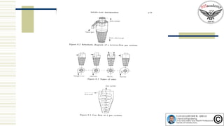
![ Figures (Othmer,
1978.) [112]
Figure a. Tangential
inlet, axial discharge.
Figure b. Tanential
inlet, peripheral
discharge
Figure c. Axial inlet,
axial discharge
Figure d. Axial inlet,
peripheral discharge](https://image.slidesharecdn.com/gassolidseparation-160411170336/85/Episode-42-Gas-Solid-Separation-15-320.jpg)


This document discusses gas-solid separation techniques, emphasizing the importance of various phases in the gas cleaning process. It details different types of gas cleaning equipment, primarily cyclone separators, including their design, operational principles, advantages, disadvantages, and key parameters affecting performance. The efficiency of separation processes, the relationship between flow rate and pressure drop, and factors for selecting appropriate equipment are also explored.


