Downloaded 73 times
![Generating & searching among alternatives: Methods
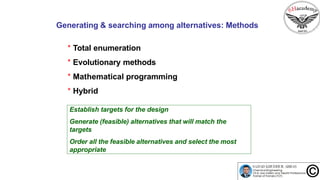
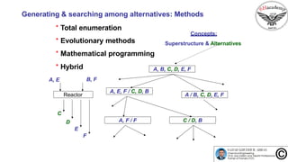
* Total enumeration
* Evolutionary methods
* Mathematical programming
* Hybrid
Concepts:
Superstructure & Alternatives
C[1]
C[2]
1
2
3
H[1]
T[in] T[out]
C[3]](https://image.slidesharecdn.com/lecture-7-process-synthesis-160414120532/85/Episode-55-Conceptual-Process-Synthesis-Design-16-320.jpg)
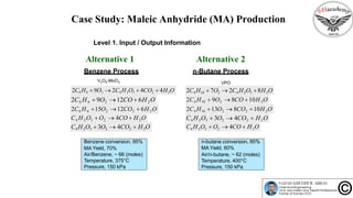


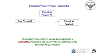
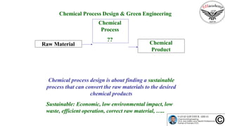
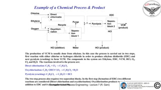
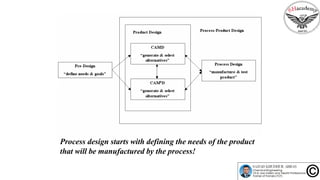
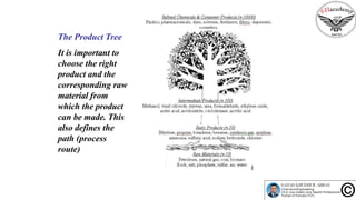
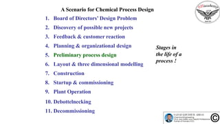
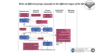
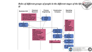
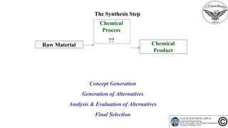
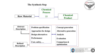
The document discusses the conceptual process synthesis and design in chemical engineering, focusing on creating sustainable processes for converting raw materials into chemical products. It outlines a multi-step process design framework, including product selection, feedback mechanisms, and construction stages, as well as methods for evaluating and optimizing design alternatives. Examples are provided, including the production of vinyl chloride monomer (VCM) from ethylene and various separation techniques used in chemical processes.