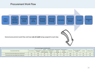
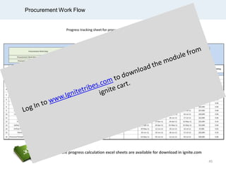
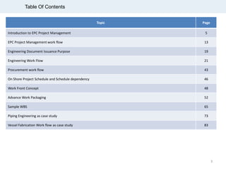
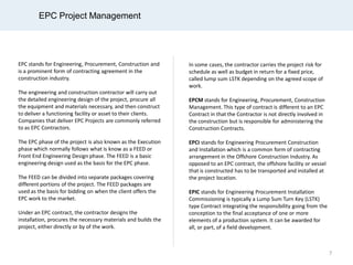
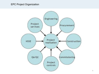
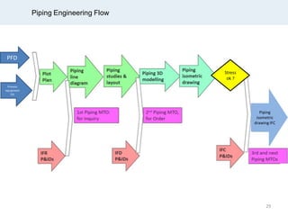
The document outlines the workflow and interdependencies involved in EPC (Engineering, Procurement, Construction) project management, detailing processes from project inception through construction. It explains various contract types such as EPC, EPCM, and EPIC, emphasizing the importance of engineering documentation and coordination among disciplines for successful project execution. Key aspects include engineering deliverables, procurement strategies, work front planning, and progress tracking to ensure that project milestones are met efficiently.

![Skid 3D Modelling – Interdependency
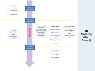
30% PDMS
30% model review
Update PDMS model 30%
Issue close out report
Report review by EPCC
contractor
60% PDMS
60% model review
Update PDMS model 60%
Issue close out report
90% PDMS
90% model review
Update PDMS model 90%
Issue close out 90% report
Report review by EPC
contractor
Receivefinal comment from
EPC contractor
Successor for 60% PDMS (issue close out report)
IFI for piping ISO
IFI [Piping Isometric]
IFA cable routing layout
IFA instrumentationlocation
IFA pipe support drawing
IFA piping GA drawing
IFA piping plan drawing
IFA structural GA drawing
Successor for 90% PDMS (issue close out report)
EPC contractorreview piping GA
EPC contractorreview piping plan
EPCcontractorreview pipe support
EPC contractorreview structural GA
32](https://image.slidesharecdn.com/epcprojectinterdepency-promo-150417084058-conversion-gate02/85/Epc-project-interdepency-and-Work-Flow-promo-32-320.jpg)
![Skid 3D Modelling – Piping GA as example
30% PDMS
30% model review
Update PDMS model 30%
Issue close out report
Report review by EPCC
contractor
60% PDMS
60% model review
Update PDMS model 60%
Issue close out report
90% PDMS
90% model review
Update PDMS model 90%
Issue close out 90% report
Report review by EPC
contractor
Receivefinal comment from
EPC contractor
Prepareand Submit IFA Rev.A [Piping GA Drawings]
EPC Contractor Review [Piping GA Drawings]
IncorporateComments & Submit IFC Rev.0 [Piping GA
Drawings]
33](https://image.slidesharecdn.com/epcprojectinterdepency-promo-150417084058-conversion-gate02/85/Epc-project-interdepency-and-Work-Flow-promo-33-320.jpg)