Downloaded 778 times
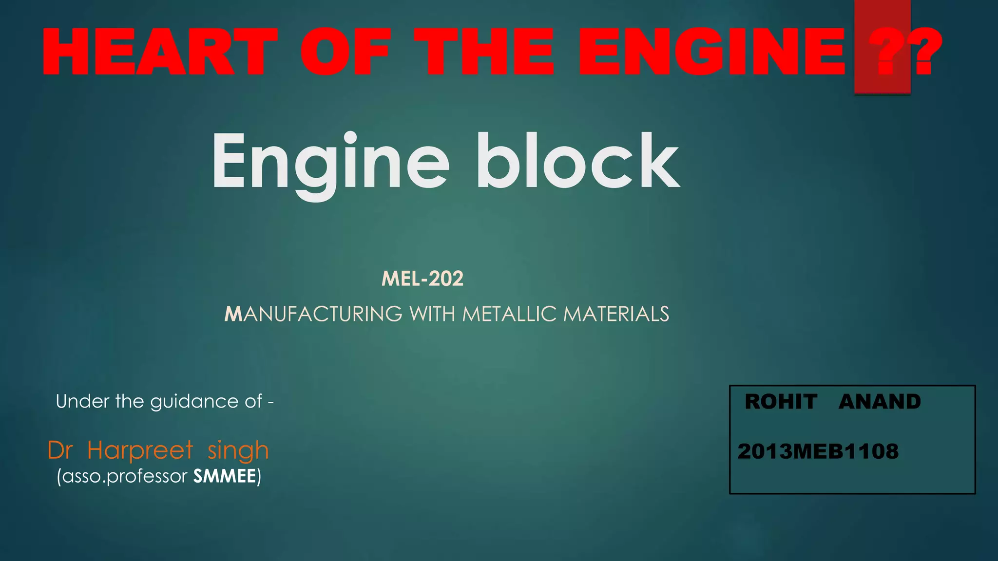
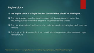
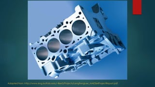
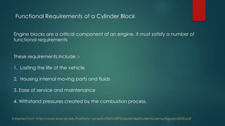

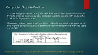
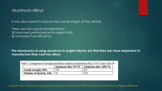
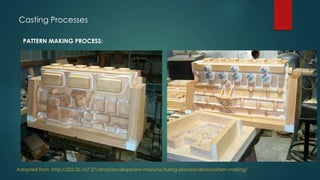
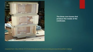


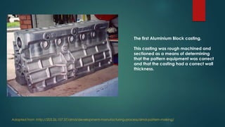


The engine block is a critical component that houses the internal parts of an engine. It is typically made of cast iron or aluminum alloys due to their ability to withstand high stresses and temperatures. The manufacturing process involves pattern making, casting, and machining. Patterns are used to create molds for casting the block. The block is then machined to final specifications. Proper material selection and manufacturing processes are needed to produce an engine block that can withstand combustion pressures and temperatures for the life of the vehicle.


![AMIF2014 – [Automotive] Pankaj Mallick, Materiali attuali e futuri per automo...](https://cdn.slidesharecdn.com/ss_thumbnails/currentandfuturematerialsforlightweightautomobiles-2014-141008051234-conversion-gate01-thumbnail.jpg?width=640&height=640&fit=bounds)


